-
Cisco IP Solution Center Traffic Engineering Management User Guide, 4.0
-
Index
-
About This Guide
-
Introduction to ISC TEM
-
Setting Up the Service
-
TE Network Discovery
-
TE Resource Management
-
Basic Tunnel Management
-
Advanced Primary Tunnel Management
-
Protection Planning
-
Traffic Admission
-
Administration
-
Task Monitoring
-
TE Topology
-
Traffic Engineering Management GUI
-
Warnings and Violations
-
Document Type Definition (DTD) File
-
 Feedback
Table Of Contents
Advanced Primary Tunnel Management
Advanced Primary Tunnel Management
In addition to the basic tunnel management tools described in "Basic Tunnel Management", ISC TEM gives access to a set of advanced tunnel planning tools that provide optimal placement of tunnels to ensure efficient use of network resources.
The advanced primary tunnel management tools are available for managed tunnels. The difference between managed and unmanaged tunnels is described in the "Managed/Unmanaged Primary Tunnels" section.
This chapter contains the following sections:
Tunnel Operations
This section explains the advanced tunnel operations in ISC TEM that incorporate the planning tools.
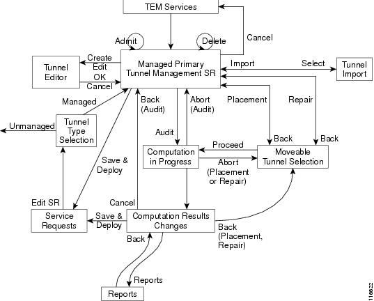
An overview of the primary tunnel management process is provided in Figure 6-1.
Figure 6-1 Primary Tunnel Management Processes
For Tunnel Type Selection, when you select Unmanaged the TE Unmanaged Primary Tunnel SR window appears (see "Basic Tunnel Management").
All other elements in Figure 6-1 are described in this chapter.
Create Primary Tunnel
To create a TE managed primary tunnel with the RG license installed, use the following steps:
Step 1
Navigate Service Inventory > Inventory and Connection Manager > Traffic Engineering Management.
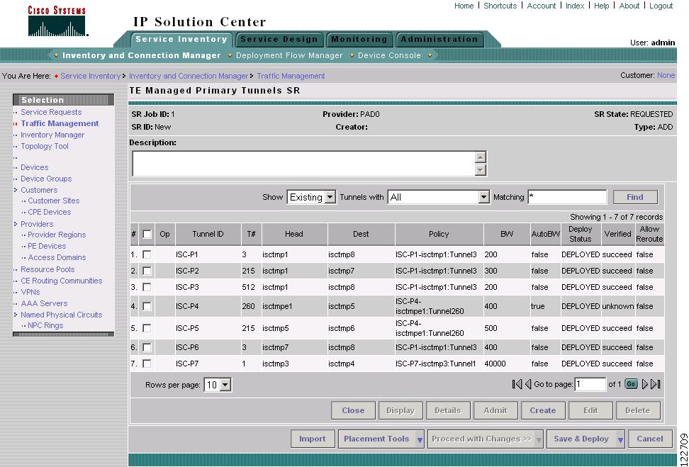
Step 2
Figure 6-2 TE Managed Primary Tunnels SR
For an explanation of the various window elements, see Create Managed TE Tunnel.
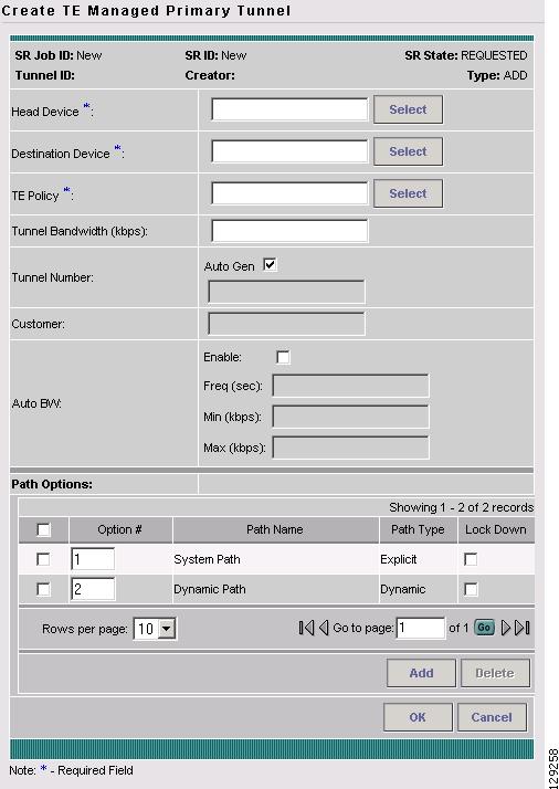
Step 3
Figure 6-3 Create TE Managed Primary Tunnel
For an explanation of the various window elements, see Create Managed TE Tunnel.
The Path Options section provides three path types, System Path, Explicit Path, and Dynamic Path.
A System Path is an ISC system generated explicit path (immovable). The first path has to be an explicit path.
An Explicit Path is a fixed path from a specific head to a specific destination device.
A Dynamic Path is provisioned by allowing the head router to find a path. The dynamic keyword is provisioned to the routers.
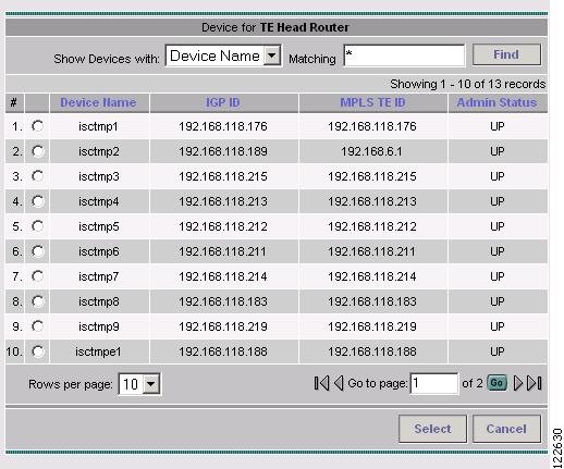
Step 4
Figure 6-4 Select Device for TE Head Router
For an explanation of the various window elements, see Create TE Managed Primary Tunnel SR.
Select a head device and click Select.
Step 5
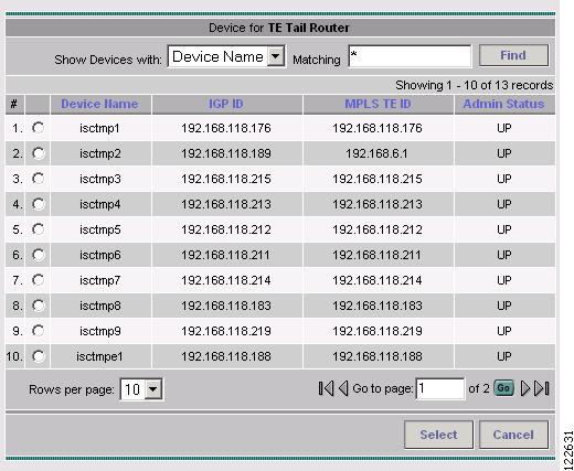
Figure 6-5 Select Device for TE Tail Router
For an explanation of the various window elements, see Create TE Managed Primary Tunnel SR.
Select a tail device and click Select.
Step 6
Note
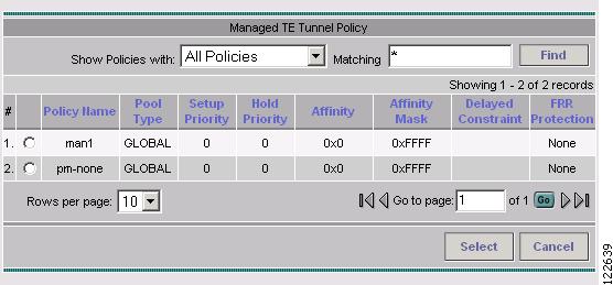
Figure 6-6 Select Managed TE Tunnel Policy
For an explanation of the various window elements, see Create TE Managed Primary Tunnel SR.
Step 7
Step 8
Step 9
In the TE Managed Primary Tunnel SR window, the Op field changes to ADD to signify that an SR has been added.
Note
Step 10
•
•
Note
Step 11
If the SR does not go to the Deployed state, go to the Task Logs window to see the deployment log (Monitoring > Task Manager > Logs) as described in Task Monitoring, page 10-1.
Edit Primary Tunnel
The only difference between creating and editing tunnels is that in the tunnel editor, the head and destination devices and tunnel number fields are not editable. Otherwise, you create and edit the same attributes.
To edit a primary tunnel, see "Basic Tunnel Management."
Delete Primary Tunnel
To delete one or more tunnels, see "Basic Tunnel Management.".
Admit Primary Tunnel
The Admit function is used to admit selected tunnels not previously verified into the managed topology. This feature is used only for discovered tunnels that failed verification.
To admit a primary tunnel, use the following steps:
Step 1
Step 2
Step 3
Import Primary Tunnel
This feature allows you to update tunnels in bulk through a file-based import mechanism. The data is migrated into the managed primary tunnel service request.
Construct XML Import File
To import tunnels from a file, first construct an XML import file conforming to the structure defined in the system supplied Document Type Definition (DTD) file (see "Document Type Definition (DTD) File"), and save the XML file together with the DTD file on the ISC server under the same directory. To create a valid import file, use the provided command line validation tool (see Command Line Validation Tool).
The following files are necessary for importing data into the ISC TEM application and are included in the installation:
•
< installedDir >/ resources/java/xml/com/cisco/vpnsc/ui/te–
–
•
–
Usage: importTeTunnels <importfile>
importfile is a XML file and must specify TeImport.dtd as its DTD. TeImport.dtd must be in the same directory as importfile.
Command Line Validation Tool
The purpose of a command line validator is to help construct a valid import file off-line that corresponds to TeImport.dtd. The tool helps screen out errors associated with files that are not well-formed and files that do not conform to the rules set by the DTD.
For instructions on how to use the DTD file, see the DTD file documentation.
The tool reads the import file line-by-line, echoes each line in on the output as it parses, and reports any parsing error it encounters. The parsing and validation continues even when parsing errors are encountered for as long as the file structure makes sense.
Note
Import Procedure
The file-based import feature is only enabled when there are no uncommitted new, changed, or deleted tunnels in the service request.
It provides a way of adding, editing, deleting, or migrating many tunnels at a time.
To start the import procedure, use the following steps:
Step 1
Step 2
Step 3
Step 4
Step 5
Note
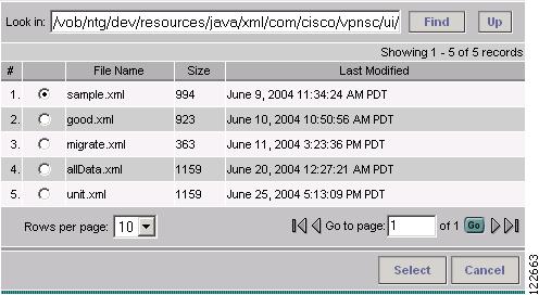
Figure 6-7 Select Import File
For an explanation of the various window elements, see Import Tunnel.
The Select Import File window lists all the XML files and any directories under the directory name shown in the Look in field.
The default directory shown in the Look in field in Figure 6-7 corresponds to the installation directory in which the DTD and sample XML files reside.
Step 6
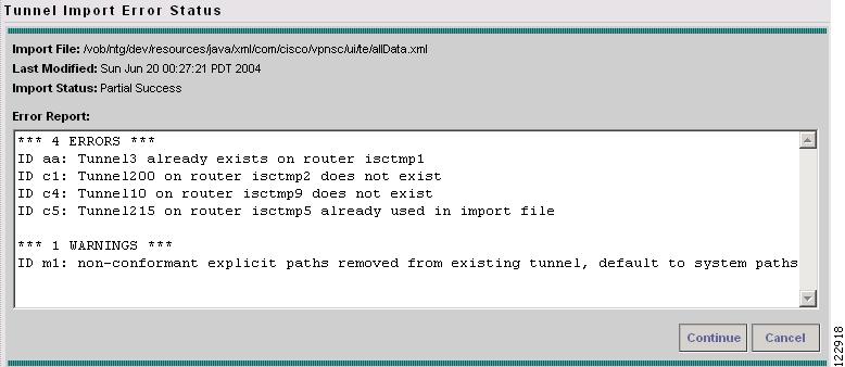
The system then parses the file. If any error is detected, it will be reported in the Tunnel Import Error Status window shown in Figure 6-8.
Figure 6-8 Tunnel Import Error Status
For an explanation of the various window elements, see Import Tunnel.
The Tunnel Import Error Status window shows the URL of the file, its last modified timestamp, the import status, and any error/warning messages.
Step 7
Step 8
Planning Strategy
The main objective of using the planning tools is to achieve optimal overall network utilization while causing minimal impact on any existing traffic on the network.
In most cases, the following strategy can be applied:
•
•
•
•
This strategy reflects the different approaches taken by the different algorithms in searching for solutions. However, other combinations are possible.
Placement Tools
Planning tools for primary tunnels are available in two buttons on the TE Primary Tunnel SR screen as shown in Figure 6-9 and Figure 6-10 depending on whether an change has been made to the managed primary tunnels.
•
•
–
–
They are accessed from two buttons in the TE Managed Primary Tunnels SR window as shown in Figure 6-9 and Figure 6-10.
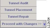
Figure 6-9 Proceed with Changes Button
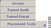
Figure 6-10 Placement Tools Button
The planning tools are described in detail in the following sections.
Tunnel Audit
When any type of change is required, whether tunnel modifications or TE resource modifications, a Tunnel Audit is run to determine what inconsistencies the change might cause, if any. Tunnel Audit can also be used anytime to check the for optimality of network utilization.
The audit can be performed from the primary tunnel window or from the TE Resource Modifications window.
Tunnel Audit can also be invoked from the Resource Management window (see "TE Resource Management").
To perform an audit on the created tunnel, use the following steps:
Step 1
Step 2
Tunnel Audit can be used in two ways:
•
•
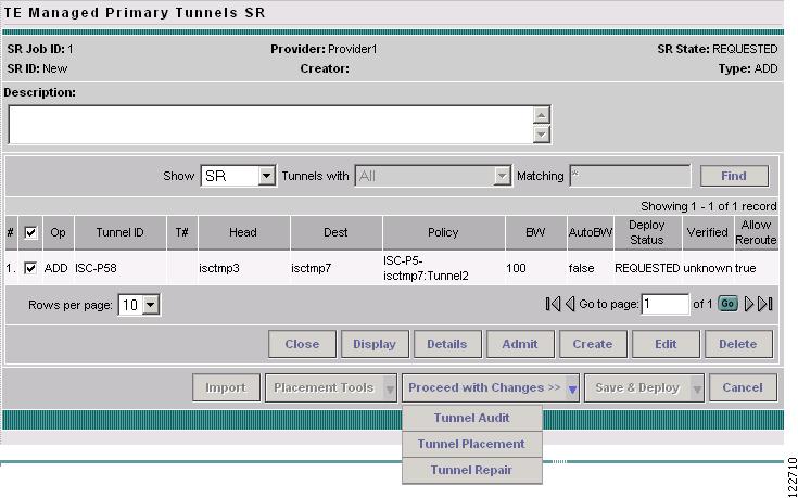
Step 3
Figure 6-11 TE Managed Primary Tunnel SR (Audit)
For an explanation of the various window elements, see Create Managed TE Tunnel.
Step 4
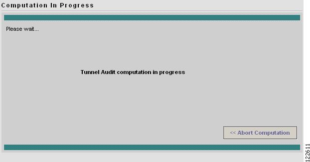
The Computation In Progress window shown in Figure 6-12 appears.
Figure 6-12 Computation In Progress - Audit
To abort the computation and return to the previous window, click << Abort Computation.
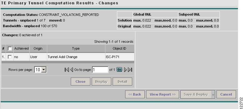
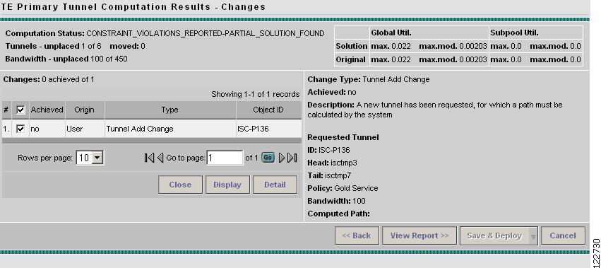
Step 5
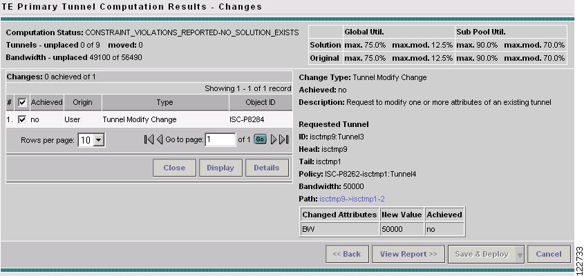
Figure 6-13 TE Primary Tunnel Computation Results - Changes
For an explanation of the various window elements, see Planning Tools.
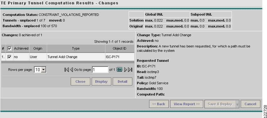
Step 6
Figure 6-14 TE Primary Tunnel Computation Results - Audit Changes (Details)
For an explanation of the various window elements, see Planning Tools.
A qualityReport is always generated. If the computation was successful, this will be the only report.
If a warning or a violation was encountered, one or more warning or violation reports will also be generated.
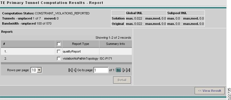
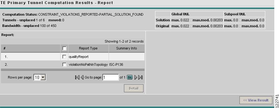
Step 7
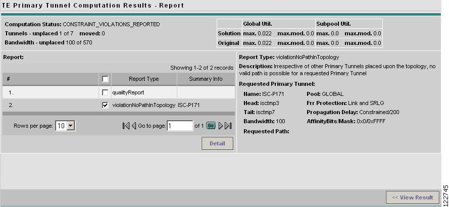
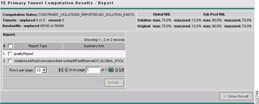
Figure 6-15 TE Primary Tunnel Computation Results - Audit Report
For an explanation of the various window elements, see Planning Tools.
In this case, as shown in Figure 6-15, both a qualityReport and a violation report have been generated.
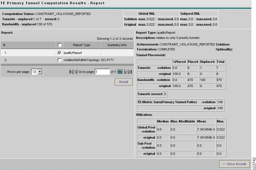
Step 8
Figure 6-16 TE Managed Primary Tunnels SR - Audit qualityReport (Details)
For an explanation of the various window elements, see Planning Tools.
The qualityReport fields in the right window pane are described in TE Primary Tunnel Computation Results - Report.
Step 9
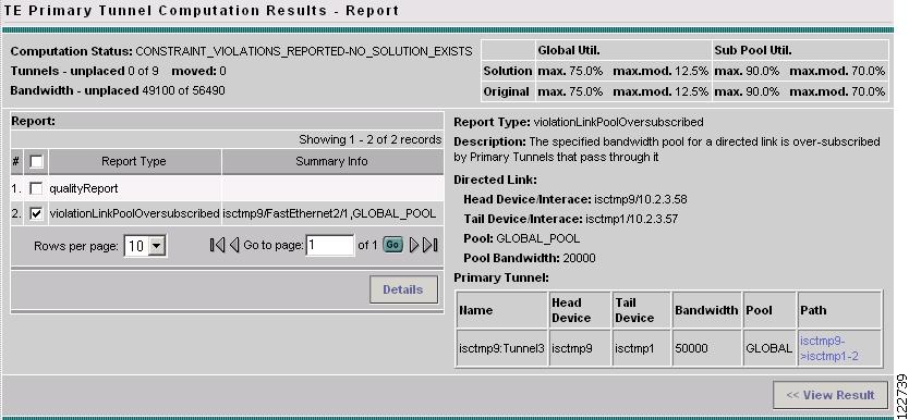
Figure 6-17 TE Managed Primary Tunnels SR - Audit Violation Report (Details_
For an explanation of the various window elements, see Planning Tools.
The report fields in the right window pane are described for each report in Appendix B, "Warnings and Violations."
Step 10
Note
Tunnel Placement
The Placement feature supports the admission of new tunnels into the network and the modification of tunnels already admitted into the network. ISC TEM will attempt to implement the changes in such a way that network utilization is optimized.
To place a created tunnel, use the following steps:
Step 1
Step 2
Step 3
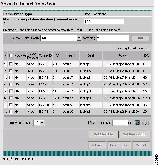
Figure 6-18 Movable Tunnel Selection - Placement
For an explanation of the various window elements, see Planning Tools.
Step 4
The user can specify whether, when admitting a new tunnel, existing tunnels can be moved (re-routed). This is configurable by the user. The default is that managed tunnels are not movable.
The user can also specify a limit on the maximum number of tunnel moves that are acceptable.
Step 5
Figure 6-19 Computation In Progress - Placement
To abort the computation and return to the previous window, click << Abort Computation.
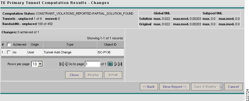
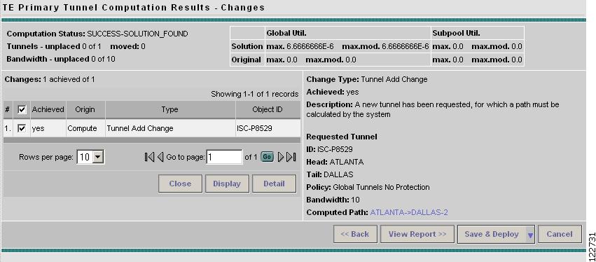
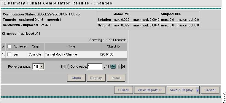
The TE Primary Tunnel Computation Results - Changes window shown in Figure 6-20 appears.
Figure 6-20 TE Primary Tunnel Computation Results - Placement Changes
For an explanation of the various window elements, see Planning Tools.
Step 6
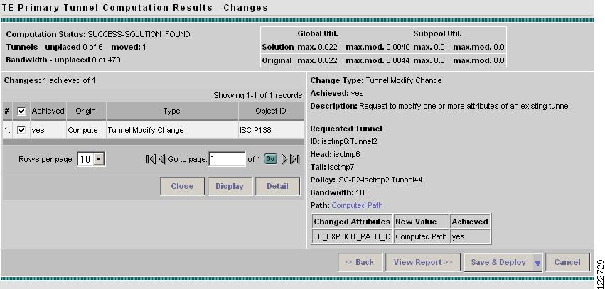
Figure 6-21 TE Primary Tunnel Computation Results - Placement Changes (Details)
For an explanation of the various window elements, see Planning Tools.
If the placement request succeeded (Achieved: yes), the Detail pane will contain a Computed Path that is selectable as shown in Figure 6-22.
Figure 6-22 TE Primary Tunnel Computation Results - Placement Changes Achieved (Details)
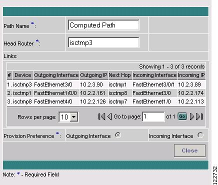
To view the path information, click the blue link in the Computed Path field. The TE Explicit Path window shown in Figure 6-23 appears.
Figure 6-23 TE Explicit Path for Placement Request
Step 7
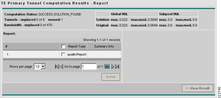
Figure 6-24 TE Primary Tunnel Computation Results - Placement Report Window
For an explanation of the various window elements, see Planning Tools.
A qualityReport is always generated. If the computation was successful, this will be the only report.
If a warning or a violation was encountered, one or more warning or violation reports will be generated as well.
Step 8
For an example of a violation report, see Figure 6-17.
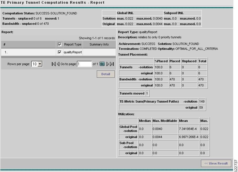
Figure 6-25 TE Managed Primary Tunnels SR - Placement Report (Details)
For an explanation of the various window elements, see Planning Tools.
The qualityReport fields in the right window pane are described in TE Primary Tunnel Computation Results - Report.
Step 9
Tunnel Repair
As changes are made to the bandwidth requirements or delay parameters of existing tunnels, inconsistencies can arise with the Tunnel Placement. The user can run a Tunnel Repair to address such inconsistencies. The objective of Tunnel Repair is to try to move as few existing tunnels as possible to accommodate the changes.
Tunnel Repair can also be invoked from the Resource Management window (see "TE Resource Management").
In the following, the case of an edited tunnel has been used:
Step 1
Step 2
Tunnel Repair can be used in two ways:
•
•
Step 3
Proceed with Changes -> Tunnel Repair
The Movable Tunnel Selection window shown in Figure 6-26 appears.
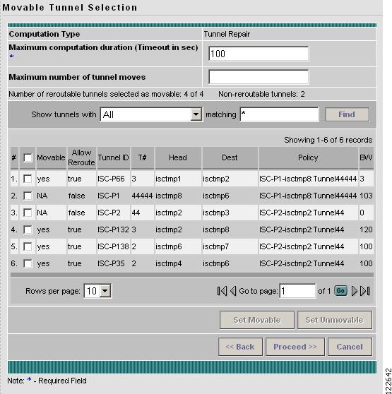
Figure 6-26 Movable Tunnel Selection - Repair
For an explanation of the various window elements, see Planning Tools.
Step 4
Tunnel Repair will only move existing tunnels if it has to. If the user does not want certain tunnels to be moved during Tunnel Repair, these tunnels should be explicitly excluded from the selected list of movable tunnels.
Note
Step 5
Figure 6-27 Computation In Progress - Repair
To abort the computation and return to the previous window, click << Abort Computation.
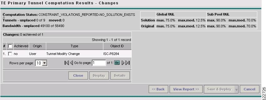
The TE Primary Tunnel Computation Results - Changes window shown in Figure 6-28 appears.
Figure 6-28 TE Primary Tunnel Computation Results - Repair Changes
For an explanation of the various window elements, see Planning Tools.
Step 6
Figure 6-29 TE Primary Tunnel Computation Results - Repair Changes (Details)
For an explanation of the various window elements, see Planning Tools.
Step 7
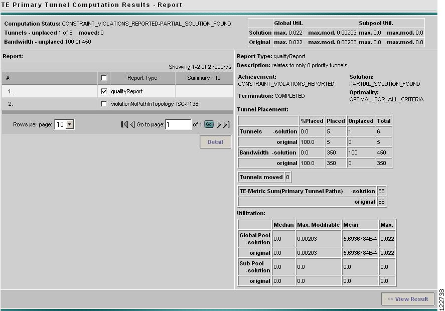
Figure 6-30 TE Primary Tunnel Computation Results - Repair Report
For an explanation of the various window elements, see Planning Tools.
A qualityReport is always generated. If the computation was successful, this will be the only report.
If a warning or a violation was encountered, one or more warning or violation reports will also be generated.
Step 8
For an example of a violation report, see Figure 6-17.
Figure 6-31 TE Managed Primary Tunnels SR - Repair Report (Details)
For an explanation of the various window elements, see Planning Tools.
The report fields in the right window pane are described for each report in Appendix B, "Warnings and Violations."
Step 9
Grooming
The purpose of grooming is to analyze the tunnel pathing with respect to the network elements and optimize resource allocation.
Grooming is not available when change requests have been created. In that case, only the placement tools under Proceed with Changes >> will be available.
To perform grooming on the network, use the following steps:
Step 1
Step 2
Step 3
Placement Tools -> Groom
The Movable Tunnel Selection window shown in Figure 6-32 appears.
Figure 6-32 Movable Tunnel Selection
For an explanation of the various window elements, see Planning Tools.
Step 4
As with Tunnel Repair, Grooming will only move existing tunnels if it has to. If you do not want certain tunnels to be moved during the Grooming process, these tunnels should be explicitly excluded from the selected list of movable tunnels.
Step 5
Figure 6-33 Computation In Progress - Grooming
To abort the computation and return to the previous window, click << Abort Computation.
The TE Primary Tunnel Computation Results - Changes window shown in Figure 6-34 appears.
Figure 6-34 TE Primary Tunnel Computation Results - Grooming Changes
For an explanation of the various window elements, see Planning Tools.
Step 6
Figure 6-35 TE Primary Tunnel Computation Results - Grooming Changes (Details)
For an explanation of the various window elements, see Planning Tools.
Step 7
Figure 6-36 TE Primary Tunnel Computation Results - Grooming Report
For an explanation of the various window elements, see Planning Tools.
A qualityReport is always generated. If the computation was successful, this will be the only report.
If a warning or a violation was encountered, one or more warning or violation reports will also be generated.
Step 8
For an example of a violation report, see Figure 6-17.
Figure 6-37 TE Managed Primary Tunnels SR - Grooming Report (Details)
For an explanation of the various window elements, see Planning Tools.
The report fields in the right window pane are described for each report in Appendix B, "Warnings and Violations."
Step 9