-
Cisco IP Solution Center Traffic Engineering Management User Guide, 4.0
-
Index
-
About This Guide
-
Introduction to ISC TEM
-
Setting Up the Service
-
TE Network Discovery
-
TE Resource Management
-
Basic Tunnel Management
-
Advanced Primary Tunnel Management
-
Protection Planning
-
Traffic Admission
-
Administration
-
Task Monitoring
-
TE Topology
-
Traffic Engineering Management GUI
-
Warnings and Violations
-
Document Type Definition (DTD) File
-
 Feedback
Table Of Contents
Access from Primary Tunnel SR Window
Access from Service Requests Window
From the Service Requests Window
Basic Tunnel Management
This chapter describes the processes involved in creating primary and backup tunnels with ISC TEM. To create a tunnel, certain steps must first be performed as described in previous chapters.
Primary tunnels are characterized by carrying traffic during normal operation. They have a prioritized list of possible paths, by which traffic can be routed. At any one time, the highest priority path available will be used to route traffic. If this fails, traffic will normally be re-routed via the next available path until a higher priority path becomes available again.
Prior to setting up the tunnel, a TE policy governing the traffic must be defined. An explicit path is created to establish the route and, in the case of a primary tunnel, it is created as either a managed or an unmanaged tunnel.
The purpose of a backup tunnel is to carry FRR protected traffic around a failed element until the routing in the network has reconverged. It is intended to protect traffic travelling along primary tunnels. There can be many backup tunnels protecting the same traffic through the use of load balancing.
If the network fails to reconverge, the backup tunnel will remain in place.
The difference between managed and unmanaged tunnels is described in Managed/Unmanaged Primary Tunnels.
The concept of bandwidth pools from which tunnels reserve bandwidth is important to understand. This is described in Bandwidth Pools.
This chapter contains the following sections:
Create TE Policy
To create a primary tunnel, each primary tunnel must be associated with a policy. A policy can be used by multiple tunnels.
For backup tunnels, this step is not necessary. In this case, proceed to Create Explicit Path.
For other TE policy management operations, see TE Policies, page 9-2.
The TE policy is a set of rules governing the TE network and defines the Class-of-Service (for example, gold, silver, bronze) for primary tunnel traffic.
ISC TEM has a notion of Managed and Unmanaged policies. Managed policies have setup/hold priorities of 0/0 and can have additional pathing constraints such as protection level and max delay. Tunnels with Unmanaged policies are provisioned by the system, but the system only tracks the deployment, not the operation of the tunnel. Unmanaged policies cannot have a setup/hold priority of zero.
Policies are managed under Policy Manager in Service Design. For a more detailed explanation of the Policy Manager GUI, see TE Policies, page 9-2.
To create a TE policy, use the following steps:
Step 1
Navigate to Service Design > Policy Manager.
Step 2
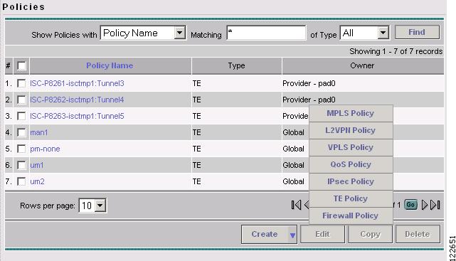
The Policies window in Figure 5-1 appears.
Figure 5-1 Policies Window
Step 3
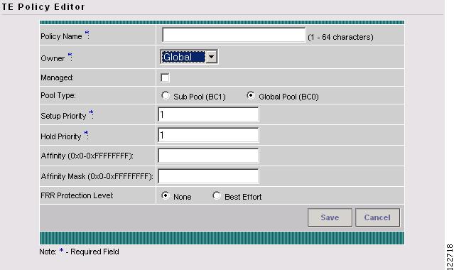
To edit an existing policy, select the policy that you want to modify and click Edit. The TE Policy Editor window in Figure 5-2 appears.
Note
Figure 5-2 TE Policy Editor
For an explanation of the various window elements, see TE Policies, page 9-2.
Step 4
If you intend to use the TE policy for managed tunnels, make sure to check the Managed check box. When setting up a policy for a managed tunnel, the Setup and Hold priorities are automatically set to zero (highest priority). In the case of a policy for an unmanaged tunnel, you can specify the desired Setup and Hold priority settings.
Step 5
Create Explicit Path
This section describes how to create a TE explicit path. For other TE explicit path operations, see TE Explicit Paths.
Paths are defined between source and destination routers, possibly with one or more hops in between. Paths are used for primary and backup tunnels in the explicit path option(s).
If you intend to create an explicit path for managed tunnels, the path should not contain any non-TE interfaces. Paths with non-TE interfaces will be filtered out by the tunnel path chooser of the tunnel editor for managed tunnels and backup tunnels (not unmanaged tunnels).
To create or edit an explicit path, use the following steps:
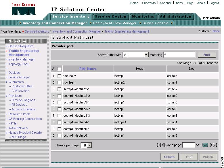
Step 1
Step 2
Figure 5-3 TE Explicit Path List
For an explanation of the various window elements, see Create/Edit Explicit Path.
Step 3
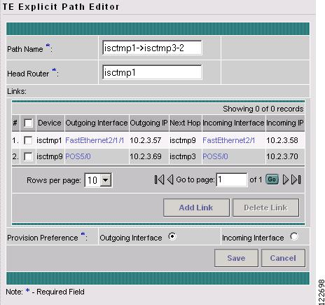
To edit an explicit path in the explicit path list, select the explicit path that you want to modify and click Edit. The TE Explicit Path Editor window in Figure 5-5 appears.
Note
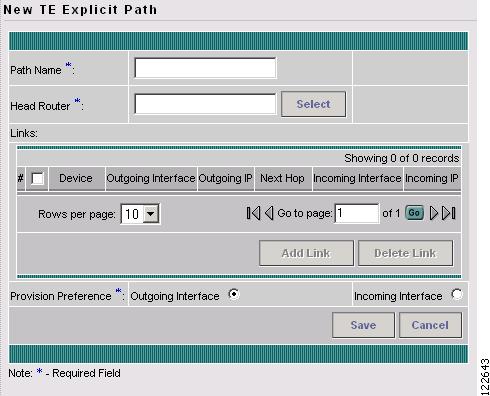
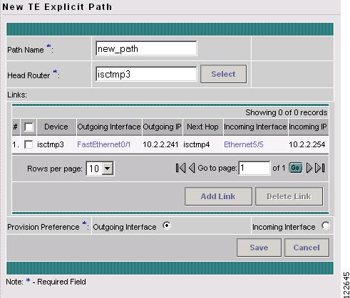
Figure 5-4 New TE Explicit Path
Figure 5-5 TE Explicit Path Editor
For an explanation of the various window elements, see Create/Edit Explicit Path and Edit TE SR (Primary or Backup).
Note
Step 4
Step 5
Step 6
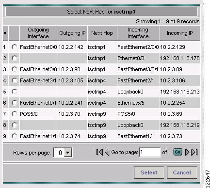
Figure 5-6 Select Next Hop
The next hop list contains all the possible next hops of the router (pop1-dus, for example), excluding the ones already included in the explicit paths (to avoid path loops).
The next hop list contains TE interfaces and one non-TE interface for each router. For TE interfaces, the Outgoing Interface and Outgoing IP columns are populated by the application.
Note
Step 7
The incoming interface field is automatically populated.
Figure 5-7 New Link for TE Explicit Path
Step 8
Step 9
Step 10
Note
Step 11
Primary Tunnel Operations
ISC TEM allows you to perform a number of primary tunnel operations, which are described in the following.
Create Primary Tunnel
After a TE Policy and an explicit path have been set up, a primary tunnel can be created. There are two types of primary tunnels:
•
•
Below, the GUI flow is described for creating unmanaged primary tunnels. It is very similar for managed primary tunnels and the few differences that exist are described in Managed/Unmanaged Primary Tunnels and Create Unmanaged TE Tunnel.
To create a managed or an unmanaged primary tunnel, use the following steps:
Step 1
Step 2
or
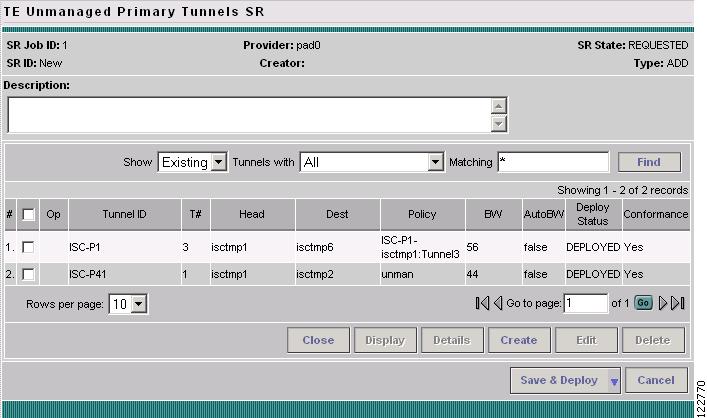
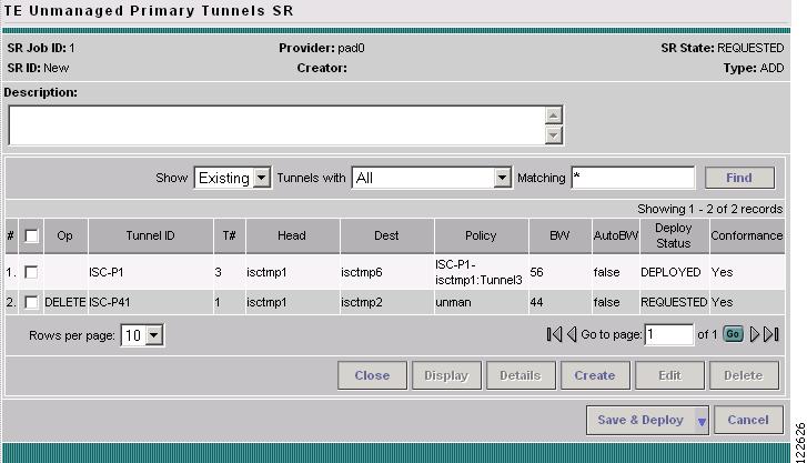
Click Create Unmanaged TE Tunnel. The TE Unmanaged Primary Tunnels SR window in Figure 5-8 appears.
In this example, we will create an unmanaged tunnel.
Figure 5-8 TE Unmanaged Primary Tunnels SR
For an explanation of the various window elements, see Create Managed TE Tunnel (same for managed and unmanaged).
Step 3
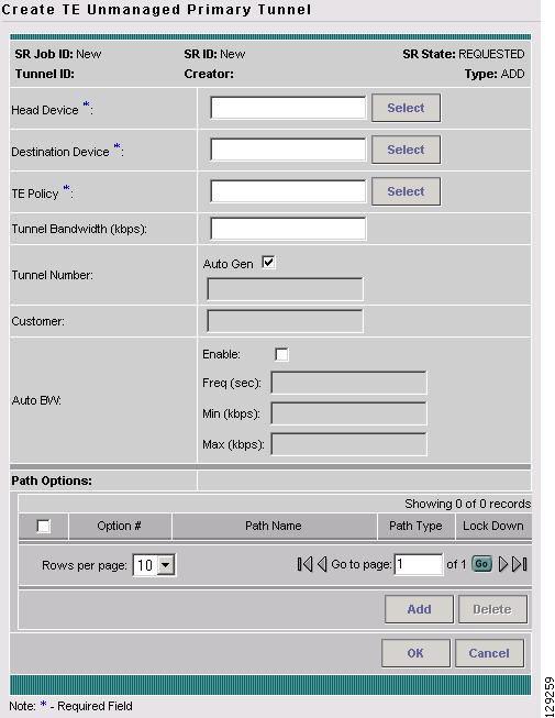
Figure 5-9 Create TE Unmanaged Primary Tunnel
For an explanation of the various window elements, see Create Managed TE Tunnel and Create Unmanaged TE Tunnel.
Step 4
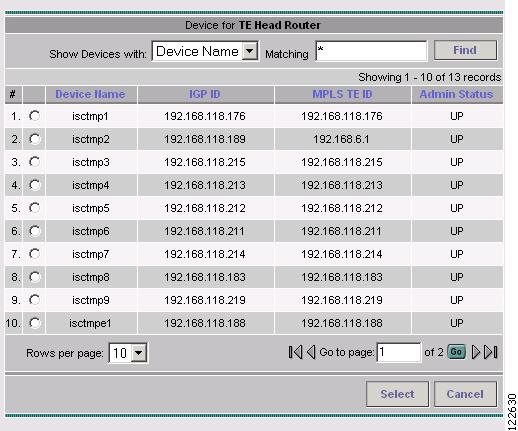
Figure 5-10 Select Device for TE Head Router
For an explanation of the various window elements, see Create Managed TE Tunnel and Create Unmanaged TE Tunnel.
Step 5
Step 6
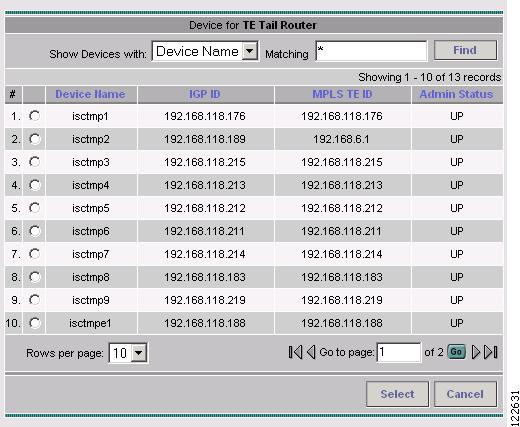
Figure 5-11 Select Device for TE Tail Router
For an explanation of the various window elements, see Create Managed TE Tunnel and Create Unmanaged TE Tunnel.
Step 7
Step 8
Note
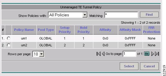
Figure 5-12 Select Unmanaged TE Tunnel Policy
For an explanation of the various window elements, see Create Managed TE Tunnel and Create Unmanaged TE Tunnel.
Step 9
Step 10
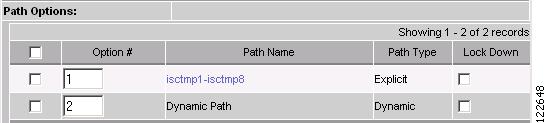
The Path Options section provides two path types, Explicit Path and Dynamic Path.
An Explicit Path is a fixed path from a specific head to a specific destination device.
A Dynamic Path is provisioned by allowing the head router to find a path. The dynamic keyword is provisioned to the routers.
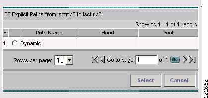
Figure 5-13 Select TE Explicit Path
For unmanaged tunnels, paths can be either explicit or dynamic.
Step 11
Click Select.
The selected path appears in the Path Options section of the create window as shown in Figure 5-14.
Figure 5-14 Path Options
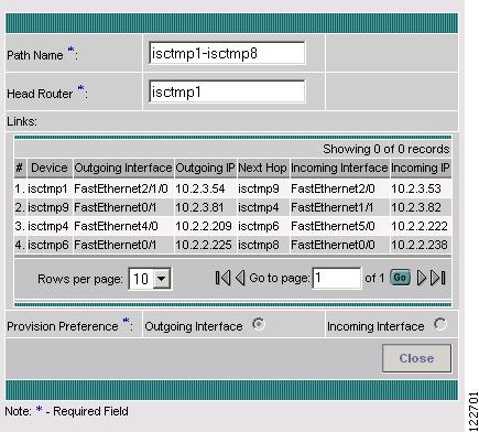
For explicit paths (<head_device>-><destination_device>), you can click the pathname to open the non-editable Explicit Path Viewer as shown in Figure 5-15.
Figure 5-15 TE Explicit Path Viewer
For an explanation of the various window elements, see Create/Edit Explicit Path.
Step 12
Step 13
Note
Step 14
For a further description of save and deploy options, see Create Managed TE Tunnel.
Note
Note
Step 15
Figure 5-16 Service Requests - Unmanaged Tunnels
If the SR does not go to the Deployed state, go to the Task Logs window to see the deployment log (Monitoring > Task Manager > Logs) as described in SR Deployment Logs, page 10-1.
To edit the service request from the Service Requests window, go back to the TE Managed Primary Tunnels SR or the TE Unmanaged Primary Tunnels SR window as described in Edit Primary Tunnel.
Edit Primary Tunnel
Primary tunnel attributes can be modified in the primary tunnel editor
There are two ways to access the primary tunnel editor:
•
•
Access from Primary Tunnel SR Window
To access the primary tunnel editor from the primary tunnel SR window (TE Managed Primary Tunnels SR or TE Unmanaged Primary Tunnels SR window) and edit a managed or an unmanaged primary tunnel, use the following steps:
Step 1
Step 2
or
Click Create Unmanaged TE Tunnel. The TE Unmanaged Primary Tunnels SR window in Figure 5-8 appears.
Step 3
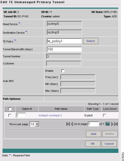
Figure 5-17 Edit TE Unmanaged Primary Tunnel
The primary tunnel editor is identical to that of the create primary tunnel GUI. For an explanation of the various window elements, see Create Managed TE Tunnel and Create Unmanaged TE Tunnel.
Step 4
Step 5
Note
Click Save & Deploy (see Note) to either deploy the new tunnel SR to the network or force deploy all tunnels, or you can create or edit more primary tunnels and then save and deploy all changes.
Step 6
Access from Service Requests Window
To access the primary tunnel editor from the Service Requests window, assuming that the SR has been created, use the following steps:
Step 1
Step 2
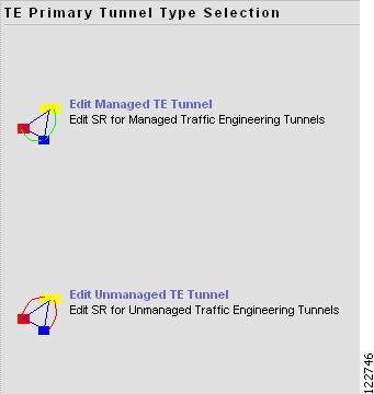
Figure 5-18 TE Primary Tunnel Type Selection
Step 3
Step 4
Go to Access from Primary Tunnel SR Window and continue the process from Step 4.
Delete Primary Tunnel
To delete a managed or an unmanaged primary tunnel from the primary tunnel SR window (TE Managed Primary Tunnels SR or TE Unmanaged Primary Tunnels SR window), use the following steps:
Step 1
Step 2
or
Click Create Unmanaged TE Tunnel. The TE Unmanaged Primary Tunnels SR window in Figure 5-8 appears.
Step 3
Figure 5-19 TE Unmanaged Primary Tunnels SR - Delete Requested
For an explanation of the various window elements, see Create Managed TE Tunnel and Create Unmanaged TE Tunnel.
Note
Click Save & Deploy to either deploy the new tunnel SR to the network or force deploy all tunnels, or you can create or edit more primary tunnels and then save and deploy all changes.
Step 4
Backup Tunnel Operations
ISC TEM allows you to perform a number of backup tunnel operations, which are described in the following.
Create Backup Tunnel
Backup tunnels are created in much the same way as primary tunnels. In both cases, building an explicit path is not required when an existing path already traverses the desired routers. A path can be used for any number of tunnels within its bandwidth capacity.
A precondition for creating a backup tunnel is the presence of an explicit path. To create an explicit path, see Create Explicit Path.
To create a backup tunnel, use the following steps:
Step 1
Step 2
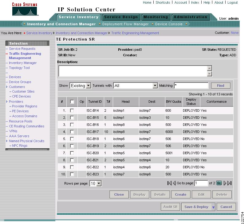
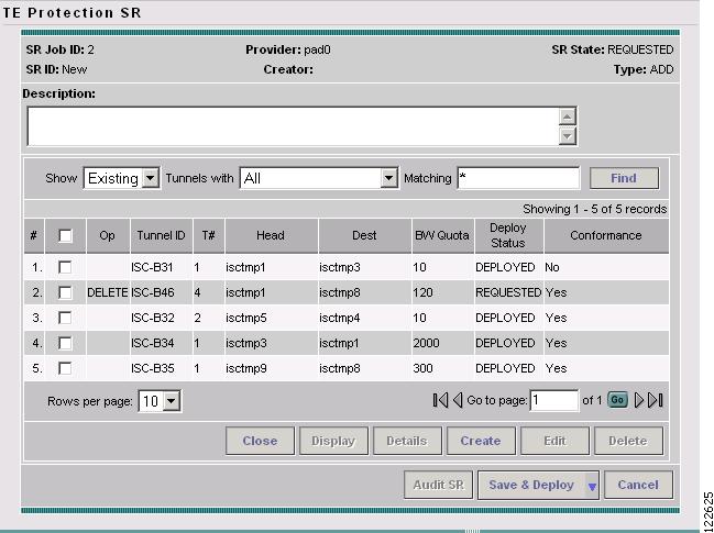
Figure 5-20 TE Protection SR
For an explanation of the various window elements, see Create TE Backup Tunnel.
Step 3
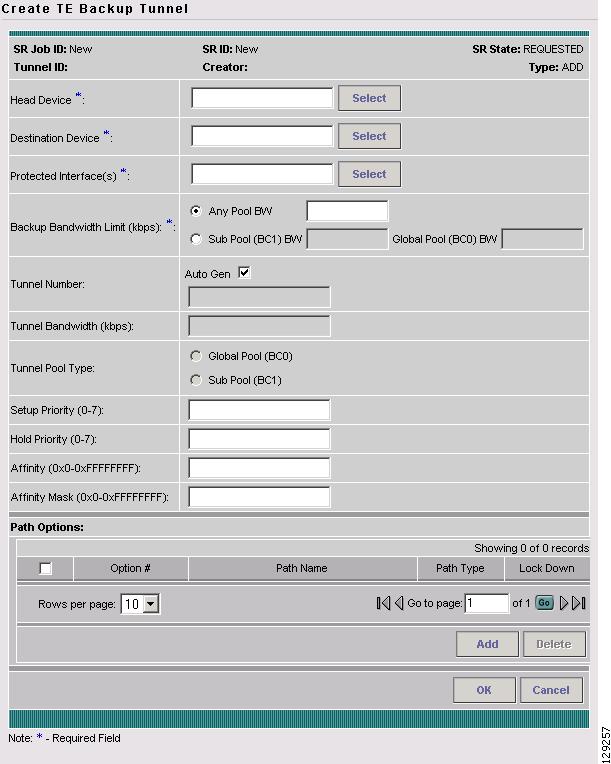
Figure 5-21 Create TE Backup Tunnel
For an explanation of the various window elements, see Create TE Backup Tunnel.
Step 4
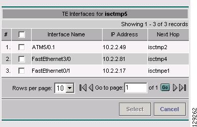
Figure 5-22 Select TE Protected Interface
For an explanation of the various window elements, see Select TE Protected Interface.
Step 5
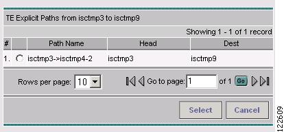
Figure 5-23 Select TE Explicit Path
Step 6
Step 7
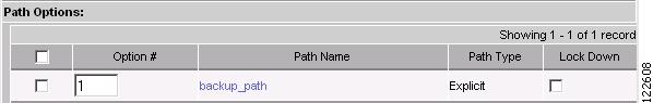
Figure 5-24 Path Options
For explicit paths, you can click the pathname to open the Explicit Path Viewer as shown in Figure 5-15.
Step 8
Step 9
Note
Step 10
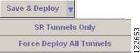
Figure 5-25 Save & Deploy Tunnels
The Save & Deploy button provides two options:
–
–
Note
Step 11
If the SR does not go to the Deployed state, go to the Task Logs window to see the deployment log (Monitoring > Task Manager > Logs) as described in SR Deployment Logs, page 10-1.
Edit Backup Tunnel
Backup tunnel attributes can be modified in the backup tunnel editor
There are two ways to access the backup tunnel editor:
•
•
From the Protection SR Window
To access the Protection SR window to edit a backup tunnel, use the following steps:
Step 1
Step 2
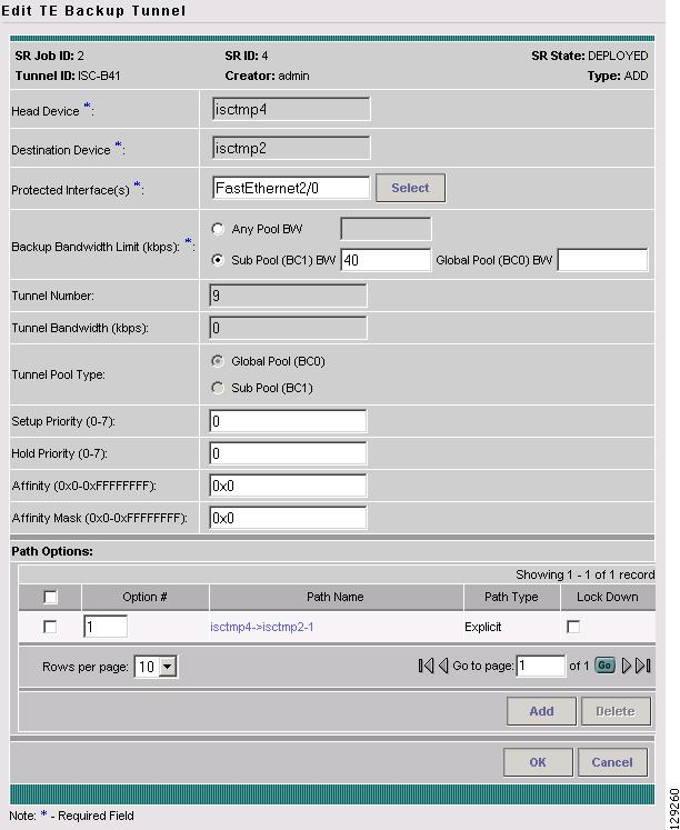
Figure 5-26 Edit TE Backup Tunnel
The backup tunnel editor is identical to that of the create backup tunnel GUI. For an explanation of the various window elements, see Create TE Backup Tunnel.
Step 3
Step 4
Note
Step 5
The Save & Deploy button options are discussed in Create Managed TE Tunnel.
Step 6
From the Service Requests Window
To edit a backup tunnel from the Service Requests window, assuming that the SR has been created use the following steps:
Step 1
Step 2
Step 3
Go to From the Protection SR Window and continue the process from Step 3.
Delete Backup Tunnel
To delete a backup tunnel from the TE Protection SR window, use the following steps:
Step 1
The TE Protection SR window in Figure 5-20 appears.
Step 2
Figure 5-27 TE Protection SR - Delete Requested
For an explanation of the various window elements, see Create TE Backup Tunnel.
Note
Click Save & Deploy to either deploy the new tunnel SR to the network or force deploy all tunnels, or you can create or edit more primary tunnels and then save and deploy all changes.
Step 3