-
Cisco IP Solution Center Traffic Engineering Management User Guide, 4.0
-
Index
-
About This Guide
-
Introduction to ISC TEM
-
Setting Up the Service
-
TE Network Discovery
-
TE Resource Management
-
Basic Tunnel Management
-
Advanced Primary Tunnel Management
-
Protection Planning
-
Traffic Admission
-
Administration
-
Task Monitoring
-
TE Topology
-
Traffic Engineering Management GUI
-
Warnings and Violations
-
Document Type Definition (DTD) File
-
 Feedback
Table Of Contents
Creating a TE Traffic Admission SR
Deploying a TE Traffic Admission SR
Traffic Admission
Tunnel admission is the first step towards enabling services on TE tunnels. There are a number of mechanisms that can be used for forwarding traffic into a tunnel to provide basic IP connectivity. The current implementation of Cisco IP Solution Center Traffic Engineering Management (ISC TEM) uses static routing.
The TE Traffic Admission tool is used to assign traffic to traffic-engineered tunnels.
This chapter contains the following sections:
•
Creating a TE Traffic Admission SR
•
Overview
Static routing is perhaps the simplest way of forwarding traffic into a tunnel. Traffic that matches a target destination prefix is routed into a particular tunnel.
While this achieves the basic goal of directing traffic into a given tunnel, this approach has limitations. First, the offering of differentiated Class-of-Service (CoS) treatment is limited to destination-based CoS. As each source PE serves as an aggregation point for a number of traffic flows, there is no way to restrict which traffic receives preferential treatment to a destination since access to a tunnel is through general routing. Second, it does not generally provide a scalable solution because the static routing mechanism must capture both the large number of subnets that can be served by each PE router, and it must be able to further capture CoS treatment for each of these subnets.
Static routing works best if there is no need to provide differentiated CoS treatment by destination. That is, all packets destined for one or more particular prefixes all receive the same CoS.
Creating a TE Traffic Admission SR
To create a TE Traffic Admission SR, use the following steps:
Step 1
Step 2
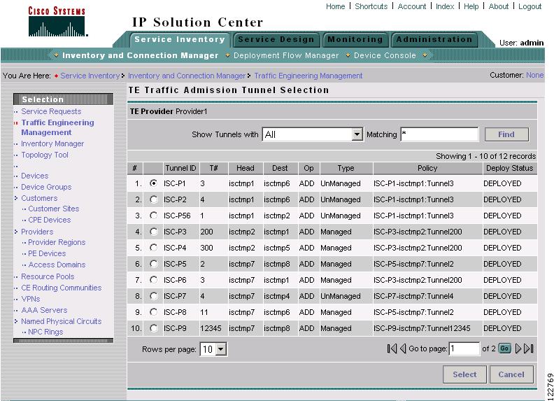
The TE Traffic Admission Tunnel Selection window in Figure 8-1 appears.
Figure 8-1 TE Traffic Admission Tunnel Selection
For an explanation of the various window elements, see Select TE Tunnel for Admission.
The TE Traffic Admission Tunnel Selection window lists all primary tunnels, both managed and unmanaged, that are not already associated with an admission SR.
The Deploy Status can be Pending, Deployed, or Functional.
Note
Step 3
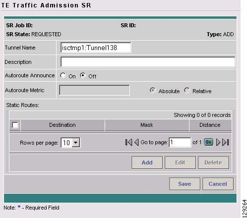
Figure 8-2 TE Traffic Admission SR
For an explanation of the various fields and buttons, see TE Traffic Admission SR.
Step 4
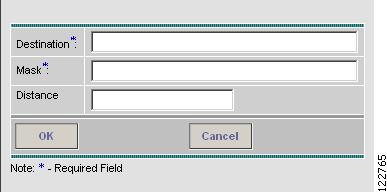
When clicking the Add button, the Add TE Static Route window in Figure 8-3 appears.
Figure 8-3 Add TE Static Route
Step 5
Click OK to accept the entries or Cancel to exit the screen.
Step 6
Step 7
To deploy the SR from the Service Requests window, see Deploying a TE Traffic Admission SR.
Deploying a TE Traffic Admission SR
As opposed to the TE Primary and Backup Tunnel SR screens, a TE Admission SR must be deployed from the general Service Requests window.
To deploy a TE Admission SR, use the following steps:
Step 1
Step 2
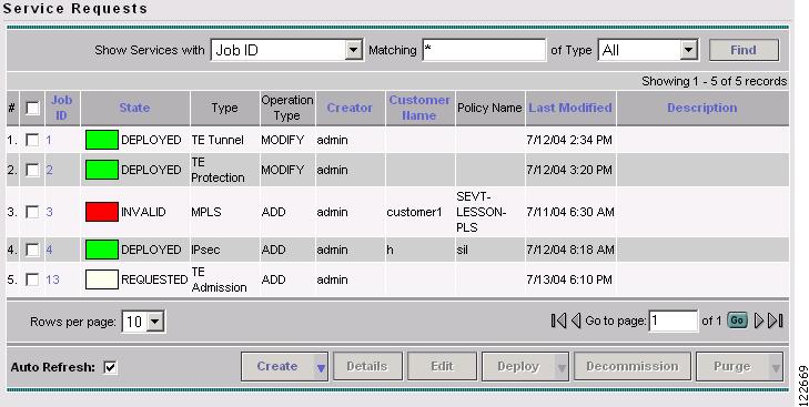
Figure 8-4 Service Requests
The Service Requests window contains the following elements:
•
•
•
•
•
•
•
•
•
Step 3
In the drop-down menu, select Deploy or Force Deploy. After having been successfully deployed, the State of the SR changes to Deployed.
Viewing the SR State
To view a service request state, go to the Service Requests window under Inventory and Connection Manager.
If the SR does not enter the Deployed state, go to the Task Logs screen to see the deployment log (Monitoring > Task Manager > Logs) as described in SR Deployment Logs, page 10-1.