-
Cisco IP Solution Center Traffic Engineering Management User Guide, 4.0
-
Index
-
About This Guide
-
Introduction to ISC TEM
-
Setting Up the Service
-
TE Network Discovery
-
TE Resource Management
-
Basic Tunnel Management
-
Advanced Primary Tunnel Management
-
Protection Planning
-
Traffic Admission
-
Administration
-
Task Monitoring
-
TE Topology
-
Traffic Engineering Management GUI
-
Warnings and Violations
-
Document Type Definition (DTD) File
-
 Feedback
Table Of Contents
Bootstrapping Process Overview
ISC TEM Client Setup and Installation
Setting Up the Service
Cisco IP Solution Center Traffic Engineering Management (ISC TEM) offers the license structure described in "Introduction to ISC TEM." The ISC TEM specific installation steps are described in this chapter whereas the general installation procedure for Cisco IP Solutions Center (ISC) is described in Cisco IP Solution Center Installation Guide, 4.0.
This chapter contains the following sections:
•
Bootstrapping Process Overview
•
Bootstrapping Process Overview
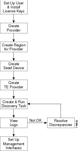
The bootstrapping process sets up key parameters that enable the system to collect TE network information and subsequently deploy TE configurations on the chosen network.
An overview of the bootstrapping process is provided in Figure 2-1.
Figure 2-1 Bootstrapping Process
The process includes the following steps:
Step 1
Step 2
Step 3
Step 4
Step 5
Note
ISC TEM Client Setup and Installation
Before setting up ISC TEM, the ISC software must be installed. To do so, see Cisco IP Solution Center Installation Guide, 4.0.
To set up a new ISC TEM user, one or more users with a TE role must be created. For step by step instructions, see Cisco IP Solution Center Infrastructure Reference, 4.0.
For an explanation of license keys in ISC, see Cisco IP Solution Center Infrastructure Reference, 4.0.
To install a TE license, use the following steps:
Step 1
•
•
Step 2
Step 3
Step 4
Step 5
Step 6
Step 7
Step 8
Step 9
•
•
•
Repeat the procedure for each license key.
Typing in all three license keys is the only valid installation.
Step 10
Step 11
You are now ready to start using ISC TEM.
Note
Creating a TE Provider
After a provider and a region for that provider have been set up (see Cisco IP Solution Center Infrastructure Reference, 4.0), create a TE provider using the following steps:
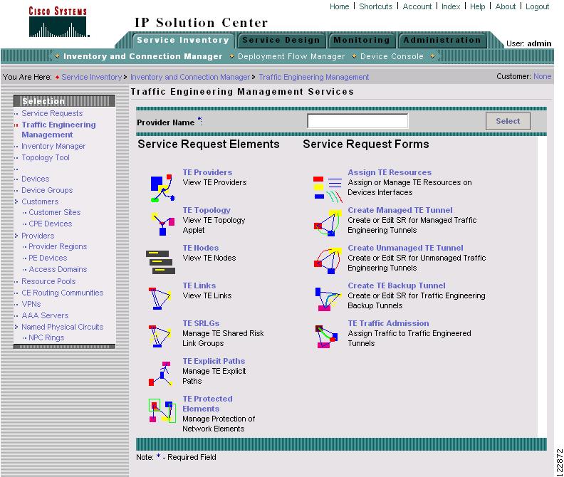
Step 1
The Traffic Engineering Management Services window shown in Figure 2-2 appears.
Figure 2-2 Traffic Engineering Management Services
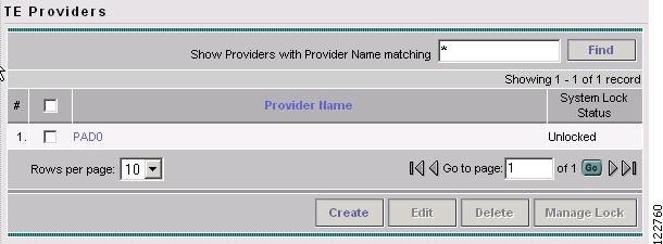
Step 2
The TE Providers window shown in Figure 2-3 appears.
Figure 2-3 TE Providers
For an explanation of the various window elements, see the "TE Providers" section.
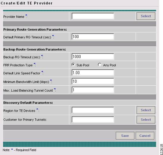
Step 3
The Create / Edit TE Provider window shown in Figure 2-4 appears.
Figure 2-4 Create/Edit TE Provider
For an explanation of the various window elements, see Create/Edit TE Provider.
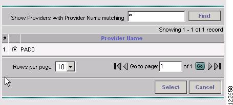
To select a provider name, click the Select button next to the Provider Name field. The Provider for Create TE Provider window shown in Figure 2-5 appears.
Step 4
Figure 2-5 Provider for Create TE Provider
Step 5
Step 6
The selected provider name is displayed in the Provider Name field.
Step 7
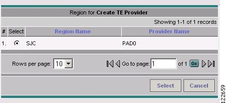
Step 8
Figure 2-6 Region for Create TE Provider
Step 9
Step 10
The selected region name is displayed in the Region for TE Devices field.
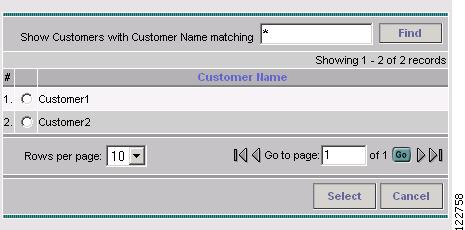
Step 11
Figure 2-7 Customer for Create TE Provider
Step 12
Step 13
The selected customer name is displayed in the Customer for Primary Tunnels field of the Create / Edit TE Provider window.
Step 14