-
Cisco Unified Communications Manager Express System Administrator Guide
-
Feature Map
-
Feature History
-
Cisco Unified CME Overview
-
Before You Begin
-
Installing and Upgrading Cisco Unified CME Software
- Setting Up Basic Configuration
-
Configuring Dialing Plans
-
Configuring Localization Support
-
Configuring Transcoding Resources
-
Configuring Video Transcoding
-
Configuring Toll Fraud Prevention
-
Enabling the GUI
-
Integrating Voice Mail
-
Configuring Security
-
Adding Features
-
Configuring Automatic Line Selection
-
Configuring Barge and Privacy
-
Configuring Call Blocking
-
Configuring Call Park
-
Call Restriction Regulations
-
Configuring Call Transfer and Forwarding
-
Configuring Call-Coverage Features
-
Configuring Caller ID Blocking
-
Configuring Conferencing
-
Configuring Video Conferences
-
Configuring Voice and Video Hardware Conferencing
-
Configuring Directory Services
-
Configuring Do Not Disturb
-
Configuring Enhanced 911 Services
-
Configuring Extension Mobility
-
Configuring Fax Relay
-
Configuring Feature Access Codes
-
Configuring Forced Authorization
-
Configuring Headset Auto-Answer
-
Configuring Intercom Lines
-
Configuring Loopback Call Routing
-
Configuring MLPP
-
Configuring Music on Hold
-
Configuring Paging
-
Configuring Presence Service
-
Configuring Ring Tones
-
Configuring Single Number Reach
-
Customizing Soft Keys
-
Configuring Speed Dial
-
Configuring Video Support
-
Configuring SSL VPN Client for SCCP IP Phones
-
-
Creating Templates
-
Modifying Cisco Unified IP Phone Options
-
Configuring Interoperability with Cisco Unified CCX
-
Configuring the CTI CSTA Protocol Suite
-
Configuring SRST Fallback Mode
-
Configuring VRF Support on Cisco Unified CME
-
Configuring the XML API
-
Index
-
 Feedback
Table Of Contents
Information About Voice-Mail Integration
Cisco Unity Connection Integration
Cisco Unity Express Integration
DTMF Integration for Legacy Voice-Mail Applications
Cisco Unity Express AXL Enhancement
How to Configure Voice-Mail Integration
SCCP: Configuring a Voice Mailbox Pilot Number
SCCP: Configuring a Mailbox Selection Policy
SCCP: Setting a Mailbox Selection Policy for Cisco Unity Express or a PBX Voice-Mail Number
SCCP: Setting Mailbox Selection Policy for Cisco Unity
SCCP: Enabling Transfer to Voice Mail
SIP: Configuring a Voice Mailbox Pilot Number
Enabling DTMF Integration for Analog Voice-Mail Applications
Enabling DTMF Integration Using RFC 2833
Enabling DTMF Integration Using SIP NOTIFY
SCCP: Configuring a Phone for MWI Outcall
SIP: Enabling MWI at the System-Level
SIP: Configuring a Directory Number for MWI
SIP: Defining Pilot Call Back Number for MWI Outcall
SIP: Configuring a Directory Number for MWI NOTIFY
Enabling SIP MWI Prefix Specification
Verifying Voice-Mail Integration
Configuration Examples for Voice-Mail Integration
Mailbox Selection Policy for SCCP Phones: Example
Voice Mailbox for SIP Phones: Example
DTMF Integration Using RFC 2833: Example
DTMF Integration Using SIP Notify: Example
DTMF Integration for Legacy Voice-Mail Applications: Example
SCCP Phone Line for MWI: Example
SIP MWI Prefix Specification: Example
SIP Directory Number for MWI Outcall: Example
SIP Directory Number for MWI Unsolicited Notify: Example
SIP Directory Number for MWI Subscribe/NOTIFY: Example
Feature Information for Voice-Mail Integration
Integrating Voice Mail
Last Updated: June 07, 2010This chapter describes how to integrate your voice-mail system with Cisco Unified Communications Manager Express (Cisco Unified CME).
Finding Feature Information in This Module
Your Cisco Unified CME version may not support all of the features documented in this module. For a list of the versions in which each feature is supported, see the "Feature Information for Voice-Mail Integration" section.
Contents
•
Information About Voice-Mail Integration
•
•
•
Prerequisites
•
•
•
Note
–
–
If the GUI files are not installed, see the "Installing Cisco Unified CME Software" section.
To determine whether the Cisco IOS software release and Cisco Unified CME software version are compatible with the Cisco Unity Express version, Cisco router model, and Cisco Unity Express hardware that you are using, see the Cisco Unity Express Compatibility Matrix.
To verify installed Cisco Unity Express software version, enter the Cisco Unity Express command environment and use the show software version user EXEC command. For information about the command environment, see the appropriate Cisco Unity Express CLI Administrator Guide at http://www.cisco.com/en/US/docs/voice_ip_comm/unity_exp/roadmap/cuedocs.html.
–
This is an example of the Cisco Unified CME license:
se-10-0-0-0> show software licensesCore:- application mode: CCME- total usable system ports: 8Voicemail/Auto Attendant:- max system mailbox capacity time: 6000- max general delivery mailboxes: 15- max personal mailboxes: 50Languages:- max installed languages: 1- max enabled languages: 1–
Information About Voice-Mail Integration
To enable voice-mail support, you should understand the following concepts:
•
•
•
•
•
•
•
Cisco Unity Connection Integration
Cisco Unity Connection transparently integrates messaging and voice recognition components with your data network to provide continuous global access to calls and messages. These advanced, convergence-based communication services help you use voice commands to place calls or listen to messages in "hands-free" mode and check voice messages from your desktop, either integrated into an e-mail inbox or from a Web browser. Cisco Unity Connection also features robust automated-attendant functions that include intelligent routing and easily customizable call-screening and message-notification options.
For instructions on how to integrate Cisco Unified CME with Cisco Unity Connection, see the Cisco CallManager Express 3.x Integration Guide for Cisco Unity Connection 1.1.
Cisco Unity Express Integration
Cisco Unity Express offers easy, one-touch access to messages and commonly used voice-mail features that enable users to reply, forward, and save messages. To improve message management, users can create alternate greetings, access envelope information, and mark or play messages based on privacy or urgency. For instructions on how to configure Cisco Unity Express, see the administrator guides for Cisco Unity Express.
For configuration information, see the "Enabling DTMF Integration Using SIP NOTIFY" section.
Note
Cisco Unity Integration
Cisco Unity is a Microsoft Windows-based communications solution that brings you voice mail and unified messaging and integrates them with the desktop applications you use daily. Cisco Unity gives you the ability to access all of your messages, voice, fax, and e-mail, by using your desktop PC, a touchtone phone, or the Internet. The Cisco Unity voice mail system supports voice-mail integration with Cisco Unified CME. This integration requires that you configure the Cisco Unified CME router and Cisco Unity software to get voice-mail service.
For configuration instructions, see the "Enabling DTMF Integration Using RFC 2833" section.
DTMF Integration for Legacy Voice-Mail Applications
For dual-tone multifrequency (DTMF) integrations, information on how to route incoming or forwarded calls is sent by a telephone system in the form of DTMF digits. The DTMF digits are sent in a pattern that is based on the integration file in the voice-mail system connected to the Cisco Unified CME router. These patterns are required for DTMF integration of Cisco Unified CME with most voice-mail systems. Voice-mail systems are designed to respond to DTMF after the system answers the incoming calls.
After configuring the DTMF integration patterns on the Cisco Unified CME router, you set up the integration files on the third-party legacy voice-mail system by following the instructions in the documents that accompany the voice-mail system. You must design the DTMF integration patterns appropriately so that the voice-mail system and the Cisco Unified CME router work with each other.
For configuration information, see the "Enabling DTMF Integration for Analog Voice-Mail Applications" section.
Mailbox Selection Policy
Typically a voice-mail system uses the number that a caller has dialed to determine the mailbox to which a call should be sent. However, if a call has been diverted several times before reaching the voice-mail system, the mailbox that is selected might vary for different types of voice-mail systems. For example, Cisco Unity Express uses the last number to which the call was diverted before it was sent to voice mail as the mailbox number. Cisco Unity and some legacy PBX systems use the originally called number as the mailbox number.
The Mailbox Selection Policy feature allows you to provision the following options from the Cisco Unified CME configuration.
•
•
•
To enable Mailbox Selection Policy, see the "SCCP: Setting a Mailbox Selection Policy for Cisco Unity Express or a PBX Voice-Mail Number" section or the "SCCP: Setting Mailbox Selection Policy for Cisco Unity" section.
RFC 2833 DTMF MTP Passthrough
In Cisco Unified CME 4.1, the RFC 2833 Dual-Tone Multifrequency (DTMF) Media Termination Point (MTP) Passthrough feature provides the capability to pass DTMF tones transparently between SIP endpoints that require transcoding or Resource Reservation Protocol (RSVP) agents.
This feature supports DTMF Relay across SIP WAN devices that support RFC 2833, such as Cisco Unity and SIP trunks. Devices registered to a Cisco Unified CME SIP back-to-back user agent (B2BUA) can exchange RFC 2833 DTMF MTP with other devices that are not registered with the Cisco Unified CME SIP B2BUA, or with devices that are registered in one of the following:
•
•
•
By default, the RFC 2833 DTMF MTP Passthrough feature uses payload type 101 on MTP, and MTP accepts all the other dynamic payload types if it is indicated by Cisco Unified CME. For configuration information, see the "Enabling DTMF Integration Using RFC 2833" section.
MWI Line Selection
Message waiting indicator (MWI) line selection allows you to choose the phone line that is monitored for voice-mail messages and that lights an indicator when messages are present.
Before Cisco Unified CME 4.0, the MWI lamp on a phone running SCCP could be associated only with the primary line of the phone.
In Cisco Unified CME 4.0 and later versions, you can designate a phone line other than the primary line to be associated with the MWI lamp. Lines other than the one associated with the MWI lamp display an envelope icon when a message is waiting. A logical phone "line" is not the same as a phone button. A button with one or more directory numbers is considered one line. A button with no directory number assigned does not count as a line.
In Cisco Unified CME 4.0 and later versions, a SIP directory number that is used for call forward all, presence BLF status, and MWI features must be configured by using the dn keyword in the number command; direct line numbers are not supported.
For configuration information, see the"SCCP: Configuring a Voice Mailbox Pilot Number" section or "SIP: Configuring a Directory Number for MWI" section.
AMWI
The AMWI (Audible Message Line Indicator) feature provides a special stutter dial tone to indicate message waiting. This is an accessibility feature for vision-impaired phone users. The stutter dial tone is defined as 10 ms ON, 100 ms OFF, repeat 10 times, then steady on.
In Cisco Unified CME 4.0(3), you can configure the AMWI feature on the Cisco Unified IP Phone 7911 and Cisco Unified IP Phone 7931G to receive audible, visual, or audible and visual MWI notification from an external voice-messaging system. AMWI cannot be enabled unless the number command is already configured for the IP phone to be configured.
Cisco Unified CME applies the following logic based on the capabilities of the IP phone and how MWI is configured:
•
•
•
•
If a phone supports (visual) MWI and AMWI and both options are configured for the phone, activate the Message Waiting light and send the stutter dial tone to the phone when it goes off-hook.
For configuration informations, see the "SCCP: Configuring a Phone for MWI Outcall" section.
SIP MWI Prefix Specification
Central voice-messaging servers that provide mailboxes for several Cisco Unified CME sites may use site codes or prefixes to distinguish among similarly numbered ranges of extensions at different sites. In Cisco Unified CME 4.0 and later versions, you can specify that your Cisco Unified CME system should accept unsolicited SIP Notify messages for MWI that include a prefix string as a site identifier.
For example, an MWI message might indicate that the central mailbox number 555-0123 has a voice message. In this example, the digits 555 are set as the prefix string or site identifier using the mwi prefix command. The local Cisco Unified CME system is able to convert 555-0123 to 0123 and deliver the MWI to the correct phone. Without this prefix string manipulation, the system would reject an MWI for 555-0123 as not matching the local Cisco Unified CME extension 0123.
To enable SIP MWI Prefix Specification, see the "Enabling SIP MWI Prefix Specification" section.
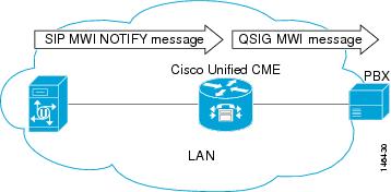
SIP MWI - QSIG Translation
In Cisco Unified CME 4.1 and later, the SIP MWI - QSIG Translation feature extends MWI functionality for SIP MWI and QSIG MWI interoperation to enable sending and receiving MWI over QSIG to a PBX.
When the SIP Unsolicited NOTIFY is received from voice mail, the Cisco router translates this event to activate QSIG MWI to the PBX, via PSTN. The PBX will switch on, or off, the MWI lamp on the corresponding IP phone. This feature supports only Unsolicited NOTIFY. Subscribe NOTIFY is not supported by this feature.
In Figure 1, the Cisco router receives the SIP Unsolicited NOTIFY, performs the protocol translation, and initiates the QSIG MWI call to the PBX, where it is routed to the appropriate phone.
Figure 1 SIP MWI to ISDN QSIG When Voice Mail and Cisco Router are On the Same LAN
It makes no difference if the SIP Unsolicited NOTIFY is received via LAN or WAN if the PBX is connected to the Cisco router, and not to the remote voice-mail server.
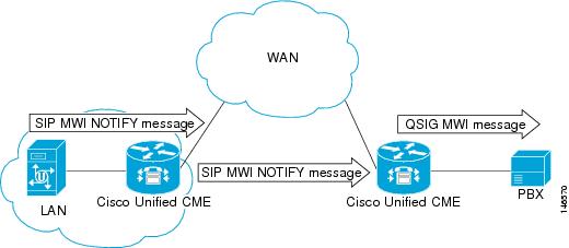
In Figure 2, a voice mail server and Cisco Unified CME are connected to the same LAN and a remote Cisco Unified CME is connected across the WAN. In this scenario, the protocol translation is performed at the remote Cisco router and the QSIG MWI message is sent to the PBX.
Figure 2 SIP MWI to ISDN QSIG When PBX is Connected to a Remote Cisco Router
VMWI
There are two types of visual message waiting indicator (VMWI) features: Frequency-shift Keying (FSK) and DC voltage. The message-waiting lamp can be enabled to flash on an analog phone that requires an FSK message to activate a visual indicator. The DC Voltage VMWI feature is used to flash the message-waiting lamp on an analog phone which requires DC voltage instead of an FSK message. For all other applications, such as MGCP, FSK VMWI is used even if the voice gateway is configured for DC voltage VMWI. The configuration for DC voltage VMWI is supported only for Foreign Exchange Station (FXS) ports on the Cisco VG224 analog voice gateway with analog device version V1.3 and V2.1.
The Cisco VG224 can only support 12 Ringer Equivalency Number (REN) for ringing 24 onboard analog FXS voice ports. To support ringing and DC Voltage VMWI for 24 analog voice ports, stagger-ringing logic is used to maximize the limited REN resource. When a system runs out of REN because too many voice ports are being rung, the MWI lamp temporarily turns off to free up REN to ring the voice ports.
DC voltage VMWI is also temporarily turned off any time the port's operational state is no longer idle and onhook, such as when one of the following events occur:
•
•
•
Once the operational state of the port changes to idle and onhook again, the MWI lamp resumes flashing until the application receives a requests to clear it; for example, if there are no more waiting messages.
For configuration information, see the "Transfer to Voice Mail" section.
Transfer to Voice Mail
The Transfer to Voice Mail feature allows a phone user to transfer a caller directly to a voice-mail extension. The user presses the TrnsfVM soft key to place the call on hold, enters the extension number, and then commits the transfer by pressing the TrnsfVM soft key again. The caller hears the complete voice mail greeting. This feature is supported using the TrnsfVM soft key or feature access code (FAC).
For example, a receptionist might screen calls for five managers. If a call comes in for a manager who is not available, the receptionist can transfer the caller to the manager's voice-mail extension by using the TrnsfVM soft key and the caller hears the personal greeting of the individual manager.
For configuration information, see the "SCCP: Enabling Transfer to Voice Mail" section.
Live Record
The Live Record feature enables IP phone users in a Cisco Unified CME system to record a phone conversation if Cisco Unity Express is the voice mail system. An audible notification, either by announcement or by periodic beep, alerts participants that the conversation is being recorded. The playing of the announcement or beep is under the control of Cisco Unity Express.
Live Record is supported for two-party calls and ad hoc conferences. In normal record mode, the conversation is recorded after the LiveRcd soft key is pressed. This puts the other party on-hold and initiates a call to Cisco Unity Express at the configured live-record number. To stop the recording session, the phone user presses the LiveRcd soft key again, which toggles between on and off.
The Live-Record number is configured globally and must match the number configured in Cisco Unity Express. You can control the availability of the feature on individual phones by modifying the display of the LiveRcd soft key using an ephone template. This feature must be enabled on both Cisco Unified CME and Cisco Unity Express.
To enable Live Record in Cisco Unified CME, see the "SCCP: Configuring Live Record" section.
Cisco Unity Express AXL Enhancement
In Cisco Unified CME 7.0(1) and later versions, the Cisco Unity Express AXL enhancement in Cisco Unified CME provides better administrative integration between Cisco Unified CME and Cisco Unity Express by automatically synchronizing passwords.
No configuration is required to enable this feature.
How to Configure Voice-Mail Integration
This section contains the following tasks:
•
•
•
•
•
•
•
•
•
•
•
•
SCCP: Configuring a Voice Mailbox Pilot Number
To configure the telephone number that is speed-dialed when the Message button on a SCCP phone is pressed, perform the following steps.
Note
Prerequisites
•
SUMMARY STEPS
1.
2.
3.
4.
5.
DETAILED STEPS
What to Do Next
•
•
•
•
SCCP: Configuring a Mailbox Selection Policy
Perform one of the following tasks, depending on which voice-mail application is used:
•
•
SCCP: Setting a Mailbox Selection Policy for Cisco Unity Express or a PBX Voice-Mail Number
To set a policy for selecting a mailbox for calls from a Cisco Unified CME system that are diverted before being sent to a Cisco Unity Express or PBX voice-mail pilot number, perform the following steps.
Prerequisites
Cisco Unified CME 4.0 or a later version.
Restrictions
In the following scenarios, the mailbox selection policy can fail to work properly:
•
•
•
SUMMARY STEPS
1.
2.
3.
or
dial-peer voice tag pots4.
5.
DETAILED STEPS
What to Do Next
•
SCCP: Setting Mailbox Selection Policy for Cisco Unity
To set a policy for selecting a mailbox for calls that are diverted before being sent to a Cisco Unity voice-mail pilot number, perform the following steps.
Prerequisites
•
•
Restrictions
This feature might not work properly in certain network topologies, including when:
•
•
•
SUMMARY STEPS
1.
2.
3.
4.
5.
DETAILED STEPS
What to Do Next
•
SCCP: Enabling Transfer to Voice Mail
To enable a phone user to transfer a call to voice mail by using the TrnsfVM soft key or a FAC, perform the following steps.
Prerequisites
•
•
•
Restrictions
The TrnsfVM soft key is not supported on the Cisco Unified IP Phone 7905, 7912, or 7921, or analog phones connected to the Cisco VG224 or Cisco ATA. These phones support the trnsfvm FAC.
SUMMARY STEPS
1.
2.
3.
4.
5.
6.
7.
8.
9.
10.
11.
12.
DETAILED STEPS
Step 1
enable
Example:Router> enable
Enables privileged EXEC mode.
•
Step 2
configure terminal
Example:Router# configure terminal
Enters global configuration mode.
Step 3
ephone-template template-tag
Example:Router(config)# ephone-template 5
Enters ephone-template configuration mode to create an ephone template.
•
Step 4
softkeys connected {[Acct] [ConfList] [Confrn] [Endcall] [Flash] [HLog] [Hold] [Join] [LiveRcd] [Park] [RmLstC] [Select] [TrnsfVM] [Trnsfer]}
Example:Router(config-ephone-template)# softkeys connected TrnsfVM Park Acct ConfList Confrn Endcall Trnsfer Hold
(Optional) Modifies the order and type of soft keys that display on an IP phone during the connected call state.
•
•
•
Step 5
exit
Example:Router(config-ephone-template)# exit
Exits ephone-template configuration mode.
Step 6
ephone phone-tag
Example:Router(config)# ephone 12
Enters ephone configuration mode.
•
Step 7
ephone-template template-tag
Example:Router(config-ephone)# ephone-template 5
Applies the ephone template to the phone.
•
Step 8
exit
Example:Router(config-ephone)# exit
Exits ephone configuration mode.
Step 9
telephony-service
Example:Router(config)# telephony-service
Enters telephony-service configuration mode.
Step 10
voicemail phone-number
Example:Router(config-telephony)# voicemail 8900
Defines the telephone number that is speed-dialed when the Messages button on a Cisco Unified IP phone is pressed.
•
Step 11
fac {standard | custom trnsfvm custom-fac}
Example:Router(config-telephony)# fac custom trnsfvm #22
Enables standard FACs or creates a custom FAC or alias.
•
•
•
Step 12
end
Example:Router(config-telephony)# end
Returns to privileged EXEC mode.
Example
The following example shows a configuration where the display order of the TrnsfVM soft key is modified for the connected call state in ephone template 5 and assigned to ephone 12. A custom FAC for transfer to voice mail is set to #22.
telephony-service
max-ephones 100
max-dn 240
timeouts transfer-recall 60
voicemail 8900
max-conferences 8 gain -6
transfer-system full-consult
fac custom trnsfvm #22
!
!
ephone-template 5
softkeys connected TrnsfVM Park Acct ConfList Confrn Endcall Trnsfer Hold
max-calls-per-button 3
busy-trigger-per-button 2
!
!
ephone 12
ephone-template 5
mac-address 000F.9054.31BD
type 7960
button 1:10 2:7
What to Do Next
•
•
SCCP: Configuring Live Record
To configure the Live Record feature so that a phone user can record a conversation by pressing the LiveRcd soft key, perform the followings steps.
Prerequisites
•
•
•
•
Restrictions
•
•
Note
SUMMARY STEPS
1.
2.
3.
4.
5.
6.
7.
8.
9.
10.
11.
12.
13.
14.
15.
16.
DETAILED STEPS
Step 1
enable
Example:Router> enable
Enables privileged EXEC mode.
•
Step 2
configure terminal
Example:Router# configure terminal
Enters global configuration mode.
Step 3
telephony-service
Example:Router(config)# telephony-service
Enters telephony-service configuration mode.
Step 4
live record number
Example:Router(config-telephony)# live record 8900
Defines the extension number that is dialed when the LiveRcd soft key is pressed on an SCCP IP phone.
Step 5
voicemail number
Example:Router(config-telephony)# voicemail 8000
Defines the extension number that is speed-dialed when the Messages button is pressed on an IP phone.
•
Step 6
exit
Example:Router(config-telephony)# exit
Exits telephony-service configuration mode.
Step 7
ephone-dn dn-tag
Example:Router(config)# ephone-dn 10
Creates a directory number that forwards all calls to the Cisco Unity Express voice-mail pilot number.
Step 8
number number [secondary number] [no-reg [both | primary]]
Example:Router(config-ephone-dn)# number 8900
Assigns an extension number to this directory number.
•
Step 9
call-forward all target-number
Example:Router(config-ephone-dn)# call-forward all 8000
Forwards all calls to this extension to the specified voice-mail number.
•
Note
Step 10
exit
Example:Router(config-ephone-dn)# exit
Exits ephone-dn configuration mode.
Step 11
ephone-template template-tag
Example:Router(config)# ephone-template 5
Enters ephone-template configuration mode to create an ephone template.
•
Step 12
softkeys connected {[Acct] [ConfList] [Confrn] [Endcall] [Flash] [HLog] [Hold] [Join] [LiveRcd] [Park] [RmLstC] [Select] [TrnsfVM] [Trnsfer]}
Example:Router(config-ephone-template)# softkeys connected LiveRcd Confrn Hold Park Trnsfer TrnsfVM
Modifies the order and type of soft keys that display on an IP phone during the connected call state.
Step 13
exit
Example:Router(config-ephone-template)# exit
Exits ephone-template configuration mode.
Step 14
ephone phone-tag
Example:Router(config)# ephone 12
Enters ephone configuration mode.
•
Step 15
ephone-template template-tag
Example:Router(config-ephone)# ephone-template 5
Applies the ephone template to the phone.
•
Step 16
end
Example:Router(config-ephone)# end
Exits to privileged EXEC mode.
Example
The following example shows Live Record is enabled at the system-level for extension 8900. All incoming calls to extension 8900 are forwarded to the voice-mail pilot number 8000 when the LiveRcd soft key is pressed, as configured under ephone-dn 10. Ephone template 5 modifies the display order of the LiveRcd soft key on IP phones.
telephony-service
privacy-on-hold
max-ephones 100
max-dn 240
timeouts transfer-recall 60
live-record 8900
voicemail 8000
max-conferences 8 gain -6
transfer-system full-consult
fac standard
!
!
ephone-template 5
softkeys remote-in-use CBarge Newcall
softkeys hold Resume Newcall Join
softkeys connected LiveRcd Confrn Hold Park Trnsfer TrnsfVM
max-calls-per-button 3
busy-trigger-per-button 2
!
!
ephone-dn 10
number 8900
call-forward all 8000
SIP: Configuring a Voice Mailbox Pilot Number
To configure the telephone number that is speed-dialed when the Message button on a SIP phone is pressed, follow the steps in this section.
Note
Prerequisites
•
SUMMARY STEPS
1.
2.
3.
4.
5.
6.
7.
8.
9.
10.
DETAILED STEPS
What to Do Next
•
•
•
Enabling DTMF Integration
Perform one of the following tasks, depending on which DTMF-relay method is required:
•
•
•
Enabling DTMF Integration for Analog Voice-Mail Applications
To set up DTMF integration patterns for analog voice-mail applications, perform the following steps.
Note
SUMMARY STEPS
1.
2.
3.
4.
[tag3 {CGN | CDN | FDN}] [last-tag]5.
[tag3 {CGN | CDN | FDN}] [last-tag]6.
[tag3 {CGN | CDN | FDN}] [last-tag]7.
[tag3 {CGN | CDN | FDN}] [last-tag]8.
[tag3 {CGN | CDN | FDN}] [last-tag]9.
DETAILED STEPS
What to Do Next
After configuring DTMF relay, you are ready to configure Message Waiting Indicator (MWI) notification for either the MWI outcall, unsolicited notify, or subscribe/notify mechanism. See the "SCCP: Configuring a Phone for MWI Outcall" section.
Enabling DTMF Integration Using RFC 2833
To configure a SIP dial peer to point to Cisco Unity and enable SIP dual-tone multifrequency (DTMF) relay using RFC 2833, use the commands in this section on both the originating and terminating gateways.
This DTMF relay method is required in the following situations:
•
•
Note
Prerequisites
•
SUMMARY STEPS
1.
2.
3.
4.
5.
6.
7.
8.
9.
10.
DETAILED STEPS
What to Do Next
After configuring DTMF relay, you are ready to configure Message Waiting Indicator (MWI) notification for either the MWI outcall, unsolicited notify, or subscribe/notify mechanism. See the "SCCP: Configuring a Phone for MWI Outcall" section.
Enabling DTMF Integration Using SIP NOTIFY
To configure a SIP dial peer to point to Cisco Unity Express and enable SIP dual-tone multifrequency (DTMF) relay using SIP NOTIFY format, follow the steps in this task.
SUMMARY STEPS
1.
2.
3.
4.
5.
6.
7.
8.
9.
10.
11.
12.
DETAILED STEPS
What to Do Next
After configuring DTMF relay, you are ready to configure Message Waiting Indicator (MWI). See the "SCCP: Configuring a Phone for MWI Outcall" section.
SCCP: Configuring a Phone for MWI Outcall
To designate a phone line or directory number on an individual SCCP phone to be monitored for voice-mail messages, or to enable audible MWI, perform the following steps.
Prerequisites
•
Restrictions
•
•
SUMMARY STEPS
1.
2.
3.
4.
5.
6.
7.
8.
9.
DETAILED STEPS
Step 1
enable
Example:Router> enable
Enables privileged EXEC mode.
•
Step 2
configure terminal
Example:Router# configure terminal
Enters global configuration mode.
Step 3
ephone phone-tag
Example:Router(config)# ephone 36
Enters ephone configuration mode.
Step 4
mwi-line line-number
Example:Router(config-ephone)# mwi-line 3
(Optional) Selects a phone line to receive MWI treatment.
•
Step 5
exit
Example:Router(config-ephone)# exit
Exits ephone configuration mode.
Step 6
ephone-dn dn-tag
Example:Router(config)# ephone-dn 11
Enters ephone-dn configuration mode.
Step 7
mwi {off | on | on-off}
Example:Router(config-ephone-dn)# mwi on-off
(Optional) Enables a specific directory number to receive MWI notification from an external voice-messaging system.
Note
Step 8
mwi-type {visual | audio | both}
Example:Router(config-ephone-dn)# mwi-type audible
(Optional) Specifies which type of MWI notification to be received.
Note
Note
Step 9
end
Example:Router(config-ephone-dn)# end
Returns to privileged EXEC mode.
SIP: Enabling MWI at the System-Level
To enable a message waiting indicator (MWI) at a system-level, perform the following steps.
Prerequisites
•
SUMMARY STEPS
1.
2.
3.
4.
5.
6.
DETAILED STEPS
SIP: Configuring a Directory Number for MWI
Perform one of the following tasks, depending on whether you want to configure MWI outcall or MWI notify (unsolicited notify or subscribe/notify) for SIP endpoints in Cisco Unified CME.
•
•
SIP: Defining Pilot Call Back Number for MWI Outcall
To designate a phone line on an individual SIP directory number to be monitored for voice-mail messages, perform the following steps.
Prerequisites
•
•
Restrictions
•
SUMMARY STEPS
1.
2.
3.
4.
5.
DETAILED STEPS
SIP: Configuring a Directory Number for MWI NOTIFY
To identify the MWI server and specify a directory number for receiving MWI Subscribe/NOTIFY or MWI Unsolicited NOTIFY, follow the steps in this section.
Note
Prerequisites
•
•
•
Restrictions
•
•
•
SUMMARY STEPS
1.
2.
3.
4.
5.
6.
7.
8.
DETAILED STEPS
Enabling SIP MWI Prefix Specification
To accept unsolicited SIP Notify messages for MWI that include a prefix string as a site identifier, perform the following steps.
Prerequisites
•
•
SUMMARY STEPS
1.
2.
3.
4.
DETAILED STEPS
SIP: Configuring VMWI
To enable a VMWI, perform the following steps.
Prerequisites
•
SUMMARY STEPS
1.
2.
3.
4.
5.
or
vmwi fsk
6.
7.
8.
9.
DETAILED STEPS
Verifying Voice-Mail Integration
•
•
•
•
•
Configuration Examples for Voice-Mail Integration
This section contains the following examples:
•
•
•
•
•
•
•
•
•
•
Mailbox Selection Policy for SCCP Phones: Example
The following example sets a policy to select the mailbox of the originally called number when a call is diverted to a Cisco Unity Express or PBX voice-mail system with the pilot number 7000.
dial-peer voice 7000 voip
destination-pattern 7000
session target ipv4:10.3.34.211
codec g711ulaw
no vad
mailbox-selection orig-called-num
The following example sets a policy to select the mailbox of the last number that the call was diverted to before being diverted to a Cisco Unity voice-mail system with the pilot number 8000.
ephone-dn 825
number 8000
mailbox-selection last-redirect-num
Voice Mailbox for SIP Phones: Example
The following example shows how to configure the call forward b2bua mailbox for SIP endpoints:
voice register global
voicemail 1234
!
voice register dn 2
number 2200
call-forward b2bua all 1000
call-forward b2bua mailbox 2200
call-forward b2bua noan 2201 timeout 15
mwi
DTMF Integration Using RFC 2833: Example
The following example shows the configuration for DTMF Relay using RFC 2833:
dial-peer voice 1 voip
destination-pattern 4...
session target ipv4:10.8.17.42
session protocol sipv2
dtmf-relay sip-notify rtp-nte
DTMF Integration Using SIP Notify: Example
The following example shows the configuration for DTMF using SIP Notify:
dial-peer voice 1 voip
destination-pattern 4...
session target ipv4:10.5.49.80
session protocol sipv2
dtmf-relay sip-notify
b2bua
DTMF Integration for Legacy Voice-Mail Applications: Example
The following example sets up DTMF integration for an analog voice-mail system.
vm-integration
pattern direct 2 CGN *
pattern ext-to-ext busy 7 FDN * CGN *
pattern ext-to-ext no-answer 5 FDN * CGN *
pattern trunk-to-ext busy 6 FDN * CGN *
pattern trunk-to-ext no-answer 4 FDN * CGN *
SCCP Phone Line for MWI: Example
The following example enables MWI on ephone 18 for line 2 (button 2), which has overlaid ephone-dns. Only a message waiting for the first ephone-dn (2021) on this line will activate the MWI lamp. Button 4 is unused. The line numbers in this example are as follows:
•
•
•
•
•
ephone-dn 20
number 2020
ephone-dn 21
number 2021
ephone-dn 22
number 2022
ephone-dn 23
number 2023
ephone-dn 24
number 2024
ephone-dn 25
number 2025
ephone 18
button 1:20 2o21,22,23,24,25 3x2 5:26
mwi-line 2
The following example enables MWI on ephone 17 for line 3 (extension 609). In this example, the button numbers do not match the line numbers because buttons 2 and 4 are not used. The line numbers in this example are as follows:
•
•
•
•
•
ephone-dn 17
number 607
ephone-dn 18
number 608
ephone-dn 19
number 609
ephone 25
button 1:17 3:18 5:19
mwi-line 3
SIP MWI Prefix Specification: Example
The following example identifies the SIP server for MWI notification at the IP address 172.16.14.22. It states that the Cisco Unified CME system will accept unsolicited SIP Notify messages for known mailbox numbers using the prefix 555.
sip-ua
mwi-server 172.16.14.22 unsolicited
telephony-service
mwi prefix 555
SIP Directory Number for MWI Outcall: Example
The following example shows an MWI callback pilot number:
voice register dn
number 9000....
mwi
SIP Directory Number for MWI Unsolicited Notify: Example
The following example shows how to specify voice-mail server settings on a UA. The example includes the unsolicited keyword, enabling the voice-mail server to send a SIP notification message to the UA if the mailbox status changes and specifies that voice dn 1, number 1234 on the SIP phone in Cisco Unified CME will receive the MWI notification:
sip-ua
mwi-server dns:server.yourcompany.com expires 60 port 5060 transport udp unsolicited
voice register dn 1
number 1234
mwi
SIP Directory Number for MWI Subscribe/NOTIFY: Example
The following example shows how to define an MWI server and specify that directory number 1, number 1234 on a SIP phone in Cisco Unified CME is to receive the MWI notification:
sip-ua
mwi-server ipv4:1.5.49.200
voice register dn 1
number 1234
mwi
Additional References
The following sections provide references related to Cisco Unified CME features.
Related Documents
Cisco Unified CME configuration
•
Cisco IOS commands
•
Cisco IOS configuration
•
Phone documentation for Cisco Unified CME
Technical Assistance
Feature Information for Voice-Mail Integration
Table 4 lists the features in this module and enhancements to the features by version.
To determine the correct Cisco IOS release to support a specific Cisco Unified CME version, see the Cisco Unified CME and Cisco IOS Software Version Compatibility Matrix at http://www.cisco.com/en/US/docs/voice_ip_comm/cucme/requirements/guide/33matrix.htm.
Use Cisco Feature Navigator to find information about platform support and software image support. Cisco Feature Navigator enables you to determine which Cisco IOS software images support a specific software release, feature set, or platform. To access Cisco Feature Navigator, go to http://www.cisco.com/go/cfn. An account on Cisco.com is not required.
Note