-
Cisco IP Solution Center L2VPN User Guide, 4.1
-
Index
-
About This Guide
-
Getting Started with L2VPN
-
ISC L2VPN and VPLS Concepts
-
Setting Up the ISC Service
-
Creating an L2VPN Policy
-
Managing an L2VPN Service Request
-
Creating an L2TPv3 Policy
-
Managing an L2TPv3 Service Request
-
Creating a VPLS Policy
-
Managing a VPLS Service Request
-
Using Autodiscovery for L2 Services
-
Generating L2 and VPLS Reports
-
Deploying, Monitoring and Auditing Service Requests
-
Setting Up VLAN Translation
-
 Feedback
Table Of Contents
Managing an L2VPN Service Request
Introducing L2VPN Service Requests
Creating an L2VPN Service Request
Creating an L2VPN Service Request with a CE
Creating an EWS L2VPN Service Request with a CE
Creating an L2VPN Service Request without a CE
Creating an EWS L2VPN Service Request without a CE
Modifying the L2VPN Service Request
Saving the L2VPN Service Request
Managing an L2VPN Service Request
This chapter covers the basic steps to provision an L2VPN service. It contains the following sections:
•
Introducing L2VPN Service Requests
•
•
•
•
•
•
•
Introducing L2VPN Service Requests
An L2VPN service request consists of one or more end-to-end wires, connecting various sites in a point-to-point topology. When you create a service request, you enter several parameters, including the specific interfaces on the CE and PE routers.
Note
You can also integrate a Cisco IP Solution Center (ISC) template with a service request. You can associate one or more templates to the CE and the PE.
To create a service request, a Service Policy must already be defined, as described in "Creating an L2VPN Policy".
Based on the predefined L2VPN policy, an operator creates an L2VPN service request, with or without modifications to the L2VPN policy, and deploys the service. Service creation and deployment are normally performed by regular network technicians for daily operation of network provisioning.
The following steps are involved in creating a service request for Layer 2 connectivity between customer sites:
•
•
•
•
•
•
Creating an L2VPN Service Request
Perform the following steps to create an L2VPN service request.
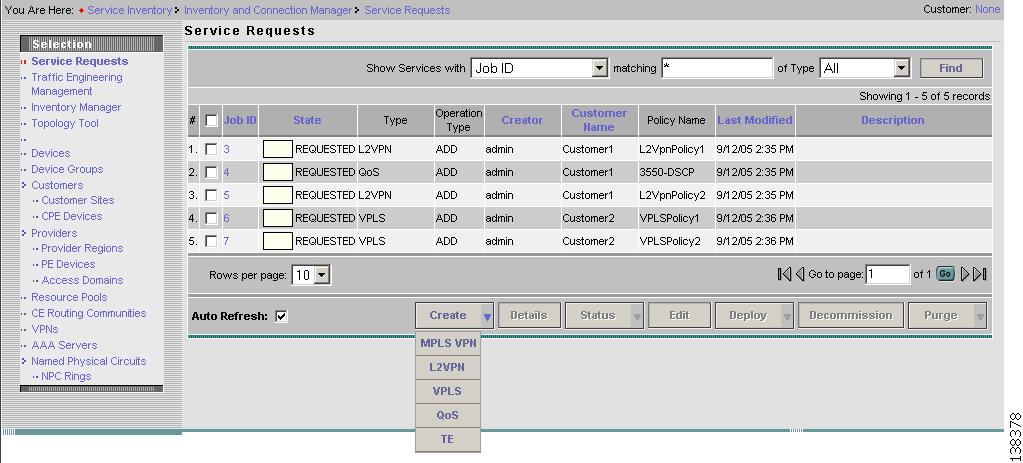
Step 1
Figure 5-1 L2VPN Service Activation
Step 2
Step 3
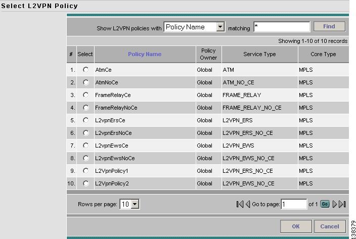
L2VPN service requests must be associated with an L2VPN policy. You choose an L2VPN policy from the policies previously created (see "Creating an L2VPN Policy").
Step 4
Figure 5-2 L2VPN Policy Choice
Step 5
As soon as you make the choice, the new service request inherits all the properties of that L2VPN policy, such as all the editable and non-editable features and pre-set parameters.
To continue creating an L2VPN service request, go to one of the following sections:
•
•
•
•
Creating an L2VPN Service Request with a CE
This section includes detailed steps for creating an L2VPN service request with a CE present for ERS, ATM, and Frame Relay policies. If you are creating an L2VPN service request for an EWS policy, go to Creating an EWS L2VPN Service Request with a CE.
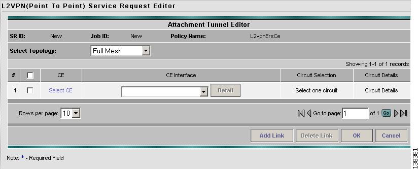
After you choose an L2VPN policy, the L2VPN Service Request Editor window appears (see Figure 5-3).
Figure 5-3 L2VPN Service Request Editor
Step 1
Note
Step 2
You specify the CE end points using the Attachment Tunnel Editor. You can create one or more CEs from a window like the one in Figure 5-4.
Figure 5-4 Select CE
Note
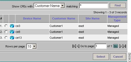
Step 3
a.
b.
c.
Figure 5-5 Select CPE Device
Step 4
Step 5
The Service Request Editor window appears displaying the name of the selected CE in the CE column.
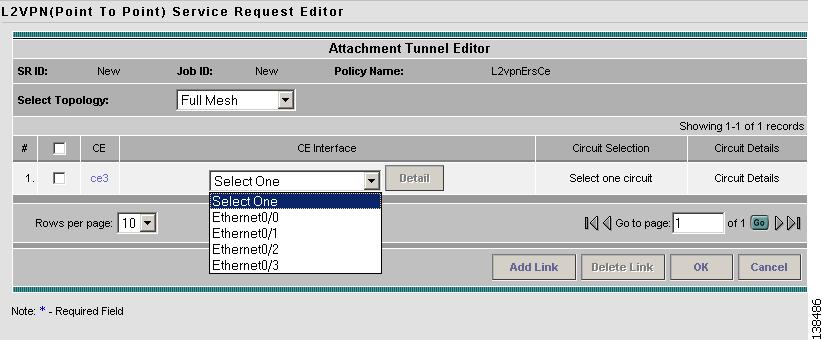
Step 6
Figure 5-6 Select the CE Interface
Note
Note
Step 7
Step 8
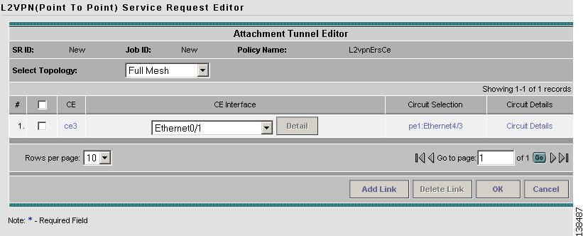
Each time you choose a CE and its interface, the NPC that was precreated from this CE and interface is automatically displayed under Circuit Selection as in Figure 5-7. This means that you do not have to further specify the PE to complete the link.
Figure 5-7 NPC Created
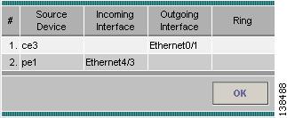
If you want to review the details of this NPC, click Circuit Details in the Circuit Details column. The NPC Details window appears and lists the circuit details for this NPC. In Figure 5-8, the CE and PE and their corresponding interfaces appear.
Figure 5-8 NPC Details
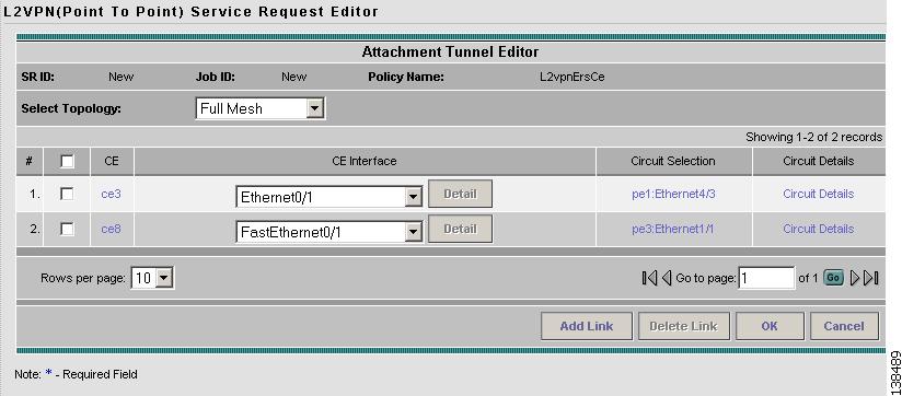
Step 9
Step 10
Figure 5-9 NPCs Created
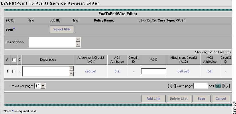
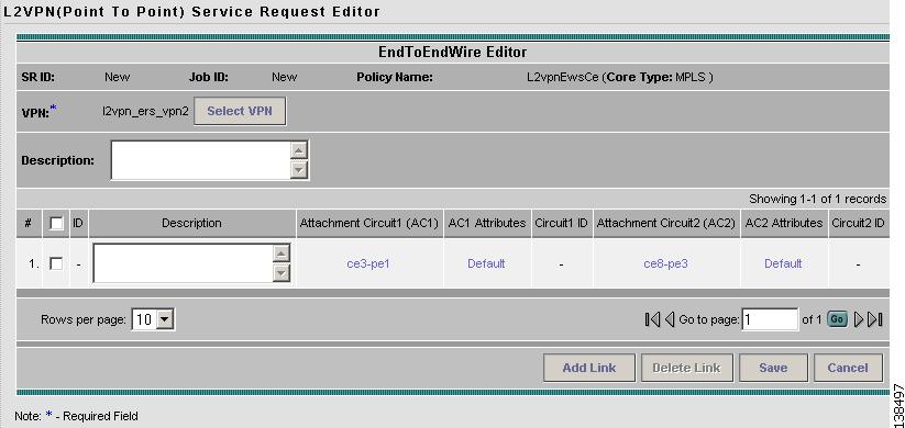
For ERS, ATM, and Frame Relay, the End-to-End Wire Editor window appears as shown in Figure 5-10.
Figure 5-10 End-to-End Wire Editor
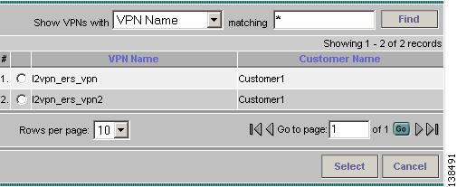
Step 11
Figure 5-11 Select VPN for L2VPN Service Request
Step 12
Figure 5-12 Attachment Circuit Selection
Step 13
Step 14
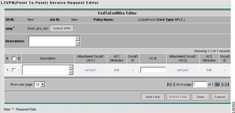
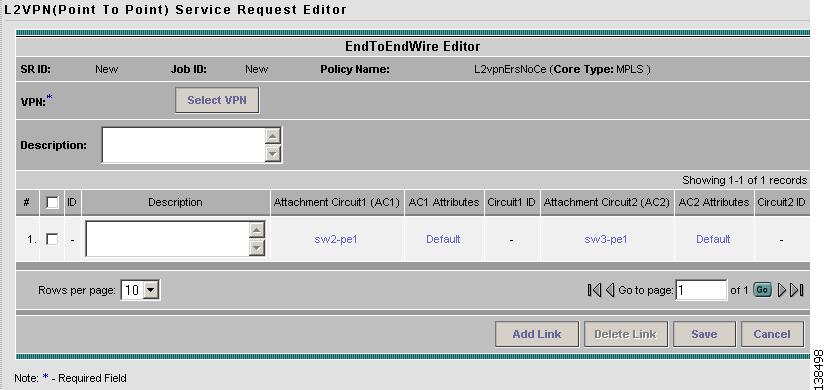
The End-to-End Wire Editor window displays the complete end-to-end wire as shown in Figure 5-13.
Figure 5-13 End-to-End Wire Created
You can choose any of the blue highlighted values to edit the End-to-End Wire.
You can edit the AC link attributes to change the default policy settings. After you edit these fields, the blue link changes from Default to Changed.
You can enter a description for the service request in the first Description field. The description will show up in this window and also in the Description column of the Service Requests window. The maximum length for this field is 256 characters.
You can enter a description for each end-to-end wire in the Description field provided for each wire. The description shows up only in this window. The data in this field is not pushed to the device(s). The maximum length for this field is 256 characters.
The ID number is system-generated identification number for the circuit.
The Circuit ID is created automatically, based on the service. For example, for Ethernet, it is based on the VLAN number; for Frame Relay, it is based on the DLCI; for ATM, it is based on the VPI/VCI.
If the policy was set up for you to define a VC ID manually, enter it into the empty VC ID field. If policy was set to "auto pick" the VC ID, ISC will supply a VC ID, and this field will not be editable. In the case where you supply the VC ID manually, if the entered value is in the provider's range, ISC validates if the entered value is available or allocated. If the entered value has been already allocated, ISC generates an error message saying that the entered value is not available and prompts you to re-enter the value. If the entered value is in the provider's range, and if it is available, then it is allocated and is removed from the VC ID pool. If the entered value is outside the provider's range, ISC displays a warning saying that no validation could be performed to verify if it is available or allocated.
You can also click Add Link to add an end-to-end wire.
You can click Delete Link to delete an end-to-end wire.
Step 15
The service request is created and saved into ISC.
Creating an EWS L2VPN Service Request with a CE
This section includes detailed steps for creating an L2VPN service request with a CE present for EWS. If you are creating an L2VPN service request for an ERS, ATM, or Frame Relay policy, go to Creating an L2VPN Service Request with a CE.
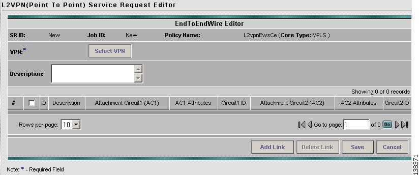
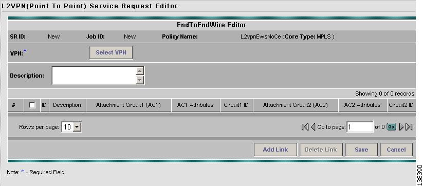
After you choose an L2VPN policy, the L2VPN Service Request Editor window appears (see Figure 5-14).
Figure 5-14 EWS Service Request Editor
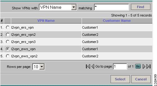
Step 1
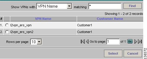
Figure 5-15 Select a VPN
Step 2
Step 3
Step 4
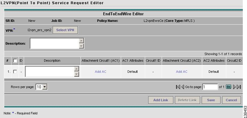
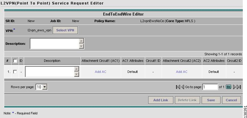
Figure 5-16 End-To-End Wire Editor
Step 5
You can enter a description for the service request in the first Description field. The description will show up in this window and also in the Description column of the Service Requests window. The maximum length for this field is 256 characters.
You can enter a description for each end-to-end wire in the Description field provided for each wire. The description shows up only in this window. The data in this field is not pushed to the device(s). The maximum length for this field is 256 characters.
The ID number is system-generated identification number for the circuit.
The Circuit ID is created automatically, based on the service. For example, for Ethernet, it is based on the VLAN number; for Frame Relay, it is based on the DLCI; for ATM, it is based on the VPI/VCI.
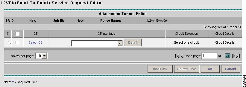
Figure 5-17 Select CE for Attachment Circuit
Step 6
This window displays the list of currently defined CEs.
a.
b.
c.
Figure 5-18 CPE for Attachment Circuit
Step 7
Step 8
Step 9
Step 10
Step 11
Each time you choose a CE and its interface, the NPC that was precreated from this CE and interface is automatically displayed under Circuit Selection as in Figure 5-19. This means that you do not have to further specify the PE to complete the link.
Step 12
Figure 5-19 NPC Created
Step 13
Step 14
Step 15
Step 16
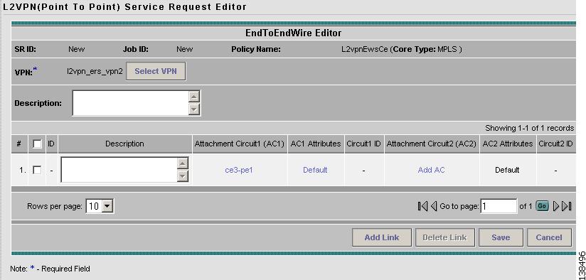
Figure 5-20 Attachment Circuits Selected
Step 17
Creating an L2VPN Service Request without a CE
This section includes detailed steps for creating an L2VPN service request without a CE present for ERS, ATM, and Frame Relay policies. If you are creating an L2VPN service request for an EWS policy, go to the Creating an EWS L2VPN Service Request without a CE.
After you choose an L2VPN policy, the L2VPN Service Request Editor window appears (see Figure 5-21).
Figure 5-21 L2VPN Service Request Editor
Step 1
Note
Step 2
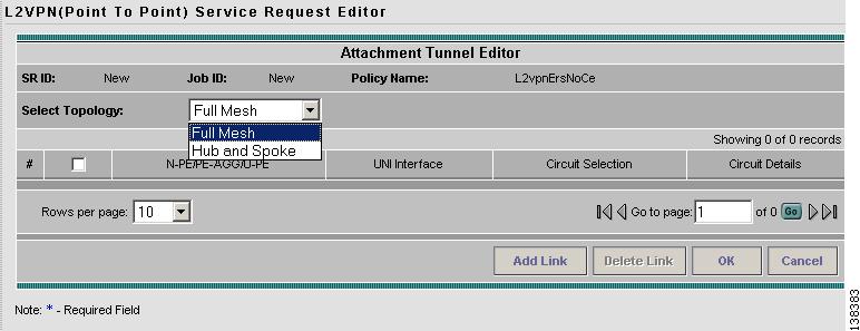
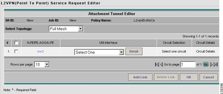
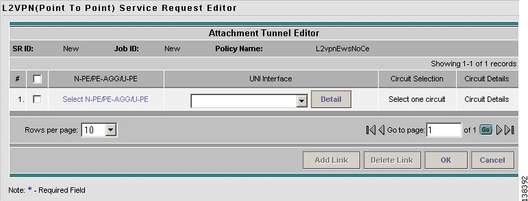
You specify the N-PE/PE-AGG/U-PE endpoints using the Attachment Tunnel Editor. You can create one or more PEs from a window like the one in Figure 5-22.
Figure 5-22 Select U-PE/PE-AGG/N-PE
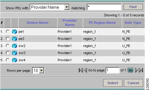
Step 3
a.
b.
c.
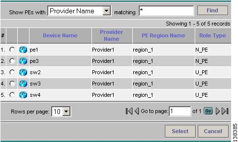
Figure 5-23 Select PE Device
Step 4
Step 5
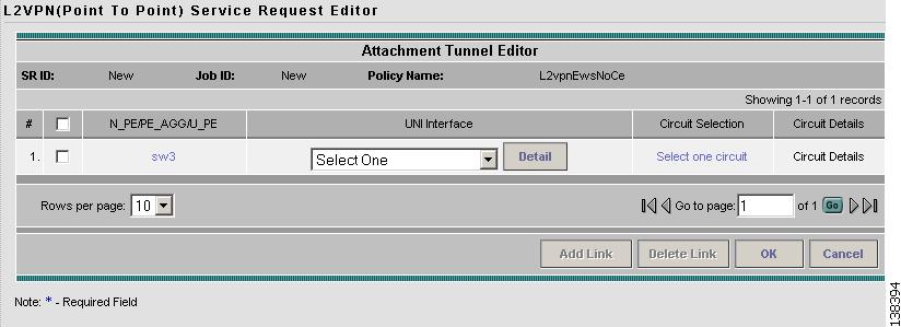
The Service Request Editor window appears displaying the name of the selected PE in the PE column.
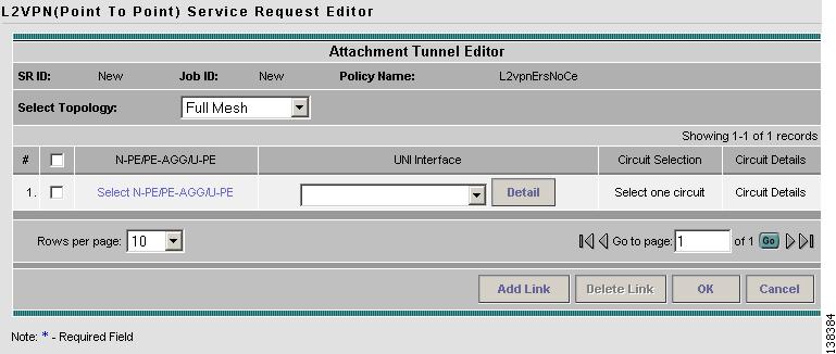
Step 6
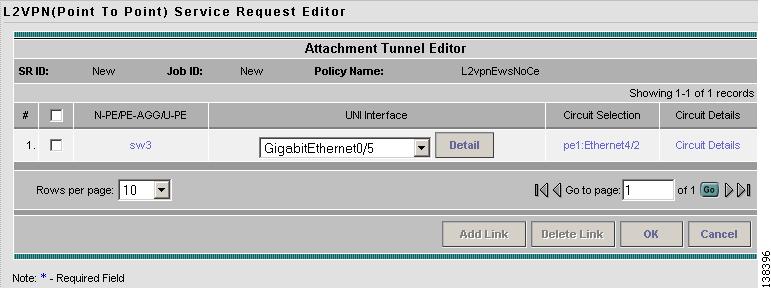
Figure 5-24 Select the UNI Interface
Note
Note
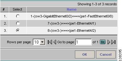
Step 7
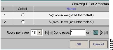
Note
Figure 5-25 Select NPC
Step 8
Step 9
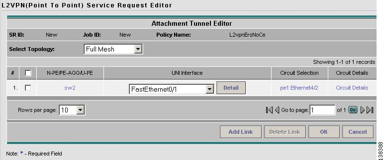
Each time you choose a PE and its interface, the NPC that was precreated from this PE and interface is automatically displayed under Circuit Selection as in Figure 5-26. This means that you do not have to further specify the PE to complete the link.
Figure 5-26 NPC Created
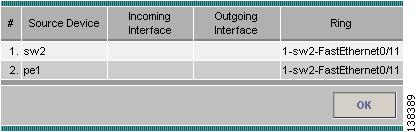
Step 10
Figure 5-27 NPC Details
After you specify all the PEs, ISC creates the links between PEs based on the Topology that you chose.
Step 11
Step 12
Step 13
Figure 5-28 End-to-End Wire Editor
Step 14
You can choose any of the blue highlighted values to edit the End-to-End Wire.
You can edit the AC link attributes to change the default policy settings. After you edit these fields, the blue link changes from Default to Changed.
You can also click Add Link to add an end-to-end wire.
You can click Delete Link to delete an end-to-end wire.
You can enter a description for the service request in the first Description field. The description will show up in this window and also in the Description column of the Service Requests window. The maximum length for this field is 256 characters.
You can enter a description for each end-to-end wire in the Description field provided for each wire. The description shows up only in this window. The data in this field is not pushed to the device(s). The maximum length for this field is 256 characters.
The ID number is system-generated identification number for the circuit.
The Circuit ID is created automatically, based on the service. For example, for Ethernet, it is based on the VLAN number; for Frame Relay, it is based on the DLCI; for ATM, it is based on the VPI/VCI.
Step 15
The service request is created and saved into ISC.
Creating an EWS L2VPN Service Request without a CE
This section includes detailed steps for creating an L2VPN service request without a CE present for EWS. If you are creating an L2VPN service request for an ERS, ATM, or Frame Relay policy, see Creating an L2VPN Service Request without a CE.
After you choose an L2VPN policy, the L2VPN Service Request Editor window appears (see Figure 5-29).
Figure 5-29 EWS Service Request Editor
Step 1
Figure 5-30 Select a VPN
Step 2
Step 3
Step 4
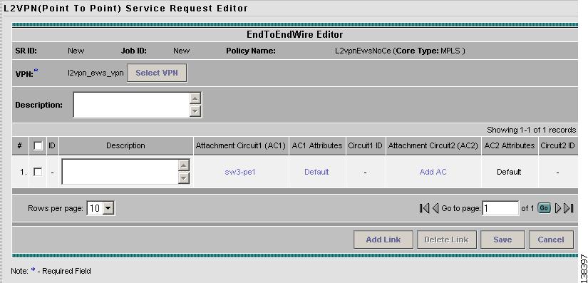
Figure 5-31 End-To-End Wire Editor
You can enter a description for the service request in the first Description field. The description will show up in this window and also in the Description column of the Service Requests window. The maximum length for this field is 256 characters.
You can enter a description for each end-to-end wire in the Description field provided for each wire. The description shows up only in this window. The data in this field is not pushed to the device(s). The maximum length for this field is 256 characters.
The ID number is system-generated identification number for the circuit.
The Circuit ID is created automatically, based on the service. For example, for Ethernet, it is based on the VLAN number; for Frame Relay, it is based on the DLCI; for ATM, it is based on the VPI/VCI.
Step 5
Figure 5-32 Select the PE for the Attachment Circuit
Step 6
This window displays the list of currently defined PEs.
a.
b.
c.
Figure 5-33 PE for Attachment Circuit
Step 7
Step 8
Step 9
Figure 5-34 PE Interface
Note
Step 10
Step 11
Note
Figure 5-35 Select NPC
Step 12
Step 13
Each time you choose a PE and its interface, the NPC that was precreated from this PE and interface is automatically displayed under Circuit Selection as in Figure 5-36. This means that you do not have to further specify the PE to complete the link.
Figure 5-36 NPC Created
Step 14
Figure 5-37 Attachment Circuit Selected
Step 15
You can enter a description for the service request in the first Description field. The description will show up in this window and also in the Description column of the Service Requests window. The maximum length for this field is 256 characters.
You can enter a description for each end-to-end wire in the Description field provided for each wire. The description shows up only in this window. The data in this field is not pushed to the device(s). The maximum length for this field is 256 characters.
The ID number is system-generated identification number for the circuit.
The Circuit ID is created automatically, based on the service. For example, for Ethernet, it is based on the VLAN number; for Frame Relay, it is based on the DLCI; for ATM, it is based on the VPI/VCI.
Step 16
Step 17
Modifying the L2VPN Service Request
After you choose all the CE end points and the NPC from the CE, go to the End-to-End Wire Editor and work on the end-to-end wire—the end-to-end connection that links two CEs. An end-to-end wire is a virtual logical link between a CE-CE pair. Each end-to-end-wire is associated with one end-to-end wire attribute and two attachment circuits (ACs). An AC is a virtual logical link between a CE-PE pair. Each AC is associated with one set of AC attributes and one or more L2VPN logical links.
Step 1
Figure 5-38 L2VPN Service Activation
Step 2
Step 3
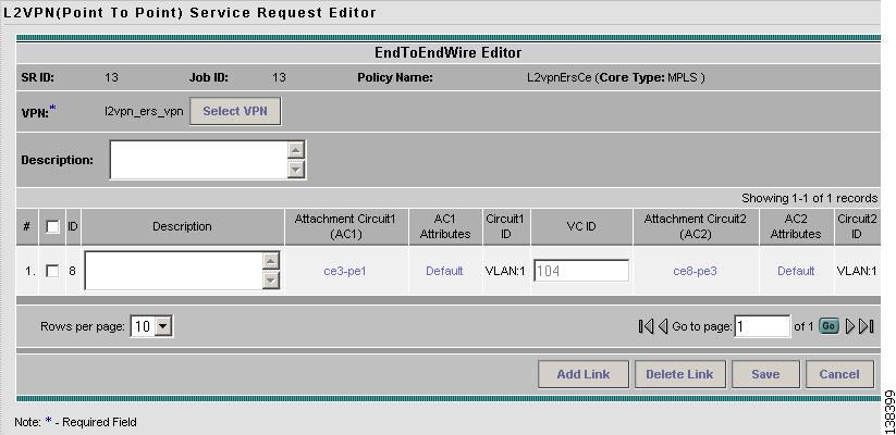
Figure 5-39 End-to-End Wire Editor
Step 4
You can choose any of the blue highlighted values to edit the End-to-End Wire.
You can edit the AC link attributes to change the default policy settings. After you edit these fields, the blue link changes from Default to Changed.
You can enter a description for the service request in the first Description field. The description will show up in this window and also in the Description column of the Service Requests window. The maximum length for this field is 256 characters.
You can enter a description for each end-to-end wire in the Description field provided for each wire. The description shows up only in this window. The data in this field is not pushed to the device(s). The maximum length for this field is 256 characters.
The Circuit ID is created automatically, based on the VLAN data for the circuit.
If the policy was set up for you to define a VC ID manually, enter it into the empty VC ID field. If policy was set to "auto pick" the VC ID, ISC will supply a VC ID, and this field will not be editable. In the case where you supply the VC ID manually, if the entered value is in the provider's range, ISC validates if the entered value is available or allocated. If the entered value has been already allocated, ISC generates an error message saying that the entered value is not available and prompts you to re-enter the value. If the entered value is in the provider's range, and if it is available, then it is allocated and is removed from the VC ID pool. If the entered value is outside the provider's range, ISC displays a warning saying that no validation could be performed to verify if it is available or allocated.
You can also click Add Link to add an end-to-end wire.
You can click Delete Link to delete an end-to-end wire.
The ID number is system-generated identification number for the circuit.
The Circuit ID is created automatically, based on the service. For example, for Ethernet, it is based on the VLAN number; for Frame Relay, it is based on the DLCI; for ATM, it is based on the VPI/VCI.
Step 5
Note
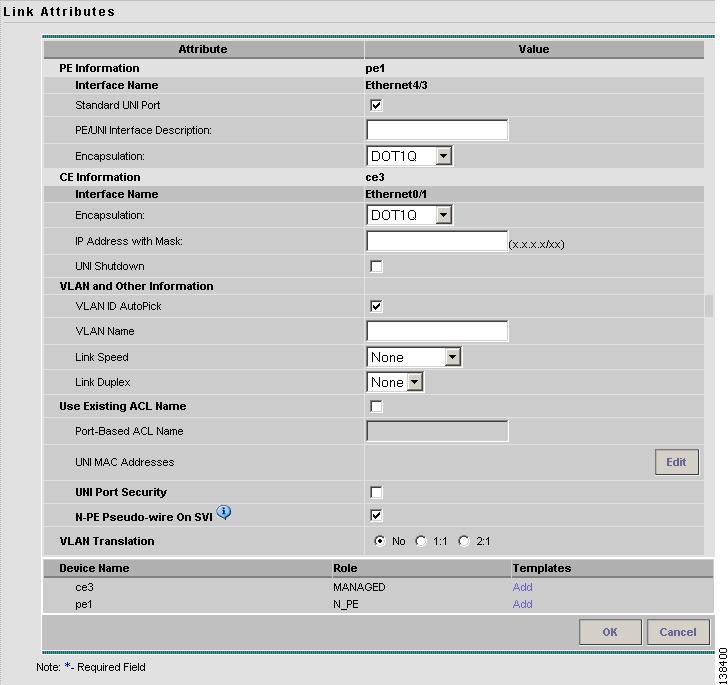
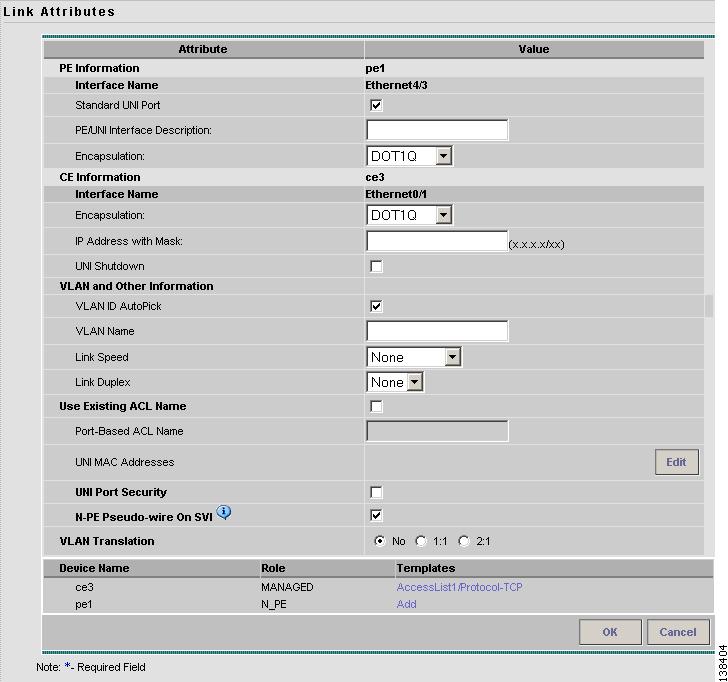
Figure 5-40 Link Attributes Window
Step 6
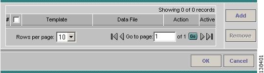
Figure 5-41 Add/Remove Templates
Step 7
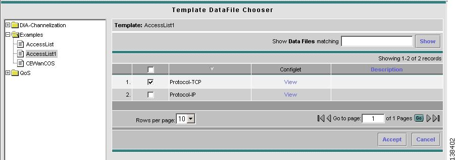
Figure 5-42 Template Datafile Chooser
Step 8
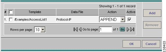
Figure 5-43 Add/Remove Templates with Templates Shown
Step 9
Step 10
Step 11
Step 12
Figure 5-44 Link Attributes with Template Added
Step 13
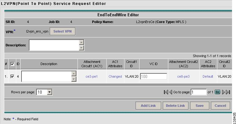
Figure 5-45 Service Request Editor with Link Attributes Changed.
Step 14
Saving the L2VPN Service Request
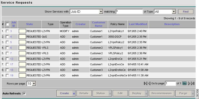
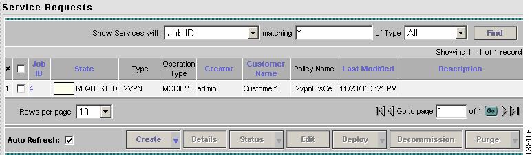
When you are finished with Link Attributes for all the Attachment Circuits, click Save to finish the L2VPN service request creation as shown in Figure 5-46.
If the L2VPN service request is successfully created, you will see the service request list window where the newly created L2VPN service request is added with the state of REQUESTED as shown in Figure 5-46. If, however, the L2VPN service request creation failed for some reason (for example, the value chosen is out of bounds), you are warned with an error message. Go back to correct the error and Save again.
Figure 5-46 L2VPN Service Request Created
The L2VPN service request is in Requested state. See Deploying Service Requests for information on deploying L2VPN service requests.