
-
Cisco IP Solution Center L2VPN User Guide, 4.1
-
Index
-
About This Guide
-
Getting Started with L2VPN
-
ISC L2VPN and VPLS Concepts
-
Setting Up the ISC Service
-
Creating an L2VPN Policy
-
Managing an L2VPN Service Request
-
Creating an L2TPv3 Policy
-
Managing an L2TPv3 Service Request
-
Creating a VPLS Policy
-
Managing a VPLS Service Request
-
Using Autodiscovery for L2 Services
-
Generating L2 and VPLS Reports
-
Deploying, Monitoring and Auditing Service Requests
-
Setting Up VLAN Translation
-
Table Of Contents
Defining an MPLS/ERS Policy with a CE
Defining an MPLS/ERS Policy without a CE
Defining an MPLS/EWS Policy with a CE
Defining an MPLS/EWS Policy without a CE
Defining an Ethernet/ERS Policy with a CE
Defining an Ethernet/ERS Policy without a CE
Defining an Ethernet/EWS Policy with a CE
Defining an Ethernet/EWS Policy without a CE
Creating a VPLS Policy
This chapter contains the basic steps to create a VPLS policy. It contains the following sections:
•
Defining an MPLS/ERS Policy with a CE
•
Defining an MPLS/ERS Policy without a CE
•
Defining an MPLS/EWS Policy with a CE
•
Defining an MPLS/EWS Policy without a CE
•
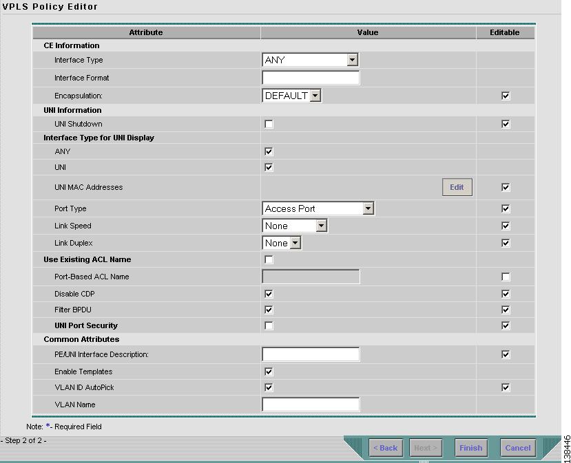
Defining an Ethernet/ERS Policy with a CE
•
Defining an Ethernet/ERS Policy without a CE
•
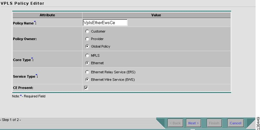
Defining an Ethernet/EWS Policy with a CE
•
Defining an Ethernet/EWS Policy without a CE
Defining a VPLS Policy
You must define a VPLS policy before you can provision a service. A VPLS policy defines the common characteristics shared by the Attachment Circuit (AC) attributes.
A policy can be shared by one or more service requests that have similar service requirements. The Editable check box gives the network operator the option of making a field editable. If the value is set to editable, the service request creator can change to other valid values for the particular policy item. If the value is not set to editable, the service request creator cannot change the policy item.
VPLS policies correspond to the one of the core types that VPLS provides:
•
MPLS core type—provider core network is MPLS enabled
•
Ethernet core type—provider core network uses Ethernet switches
and to one of the service types that VPLS provides:
•
Multi-point Ethernet Relay Service (ERS)
•
Multi-point Ethernet Wire Service (EWS)
A policy is a template of most of the parameters needed to define a VPLS service request. After you define it, a VPLS policy can be used by all the VPLS service requests that share a common set of characteristics.
You create a new VPLS policy whenever you create a new type of service or a service with different parameters. VPLS policy creation is normally performed by experienced network engineers.
To define a VPLS policy in the Cisco IP Solution Center (ISC), use the following steps. See Figure 8-1.
Step 1
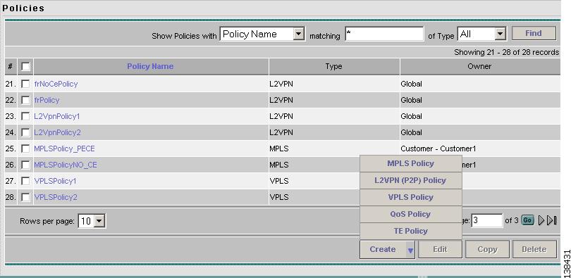
Select Service Design > Policies. The Policies window appears as show in Figure 8-1.
Figure 8-1 Creating a Policy
Step 2
Click Create.
Step 3
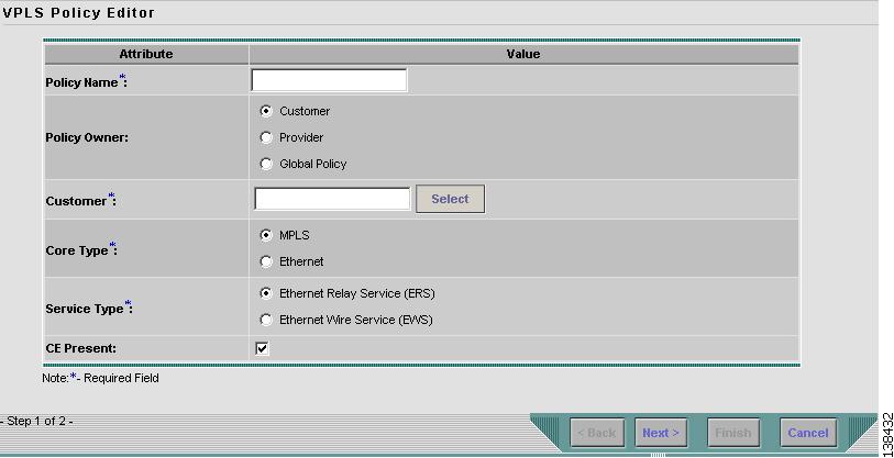
Select VPLS Policy. The VPLS Policy Editor window in Figure 8-2 appears:
Figure 8-2 Creating a VPLS Policy
Step 4
Enter a Policy Name for the VPLS policy.
Step 5
Choose the Policy Owner for the VPLS policy.
There are three types of VPLS policy ownership:
•
Customer ownership
•
Provider ownership
•
Global ownership—Any service operator can make use of this VPLS policy.
This ownership has relevance when the ISC Role-Based Access Control (RBAC) comes into play. For example, a VPLS policy that is customer owned can only be seen by operators who are allowed to work on this customer-owned policy.
Similarly, operators who are allowed to work on a provider's network can view, use, and deploy a particular provider-owned policy.
Step 6
Click Select to choose the owner of the VPLS policy. The policy owner was established when you created customers or providers during ISC setup. If the ownership is global, the Select function does not appear.
Step 7
Choose the Core Type of the VPLS policy.
There are two core types for VPLS policies:
•
MPLS—running on an IP network
•
Ethernet—all PEs are on an Ethernet provider network
Step 8
Choose the Service Type of the VPLS policy.
There are two service types for VPLS policies:
•
Multi-point Ethernet Relay Service (ERS)
•
Multi-point Ethernet Wire Service (EWS)
Step 9
Select the CE Present check box if you want ISC to ask the service operator who uses this VPLS policy to provide a CE router and interface during service activation. The default is CE present in the service.
If you do not select the CE Present check box, ISC asks the service operator, during service activation, only for the PE router and customer-facing interface.
Defining an MPLS/ERS Policy with a CE
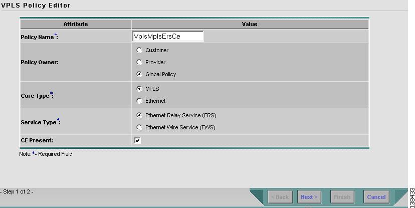
This section describes how to define a VPLS policy with an MPLS core type and an ERS service type with CE present. Figure 8-3 is an example of the first page of this policy.
Figure 8-3 MPLS/ERS Policy with a CE
Perform the following steps.
Step 1
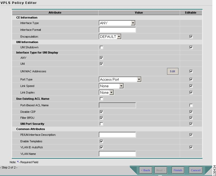
Click Next. The window in Figure 8-4 appears.
The Editable check box gives you the option of making a field editable. If you select the Editable check box, the service operator who is using this VPLS policy can modify the editable parameter during VPLS service request creation.
Figure 8-4 MPLS/ERS with a CE Policy Attributes
Step 2
Choose an Interface Type from the drop-down list.
You can choose to select a particular interface on a CE, N-PE, PE-AGG, or U-PE interface based on the service provider's POP design. The interfaces are:
•
ANY (Any interface can be chosen.)
•
Port-Channel (A bundle of ports that share the same characteristics—this gives the service provider the ability to aggregate bandwidth and protection.)
•
Ethernet
•
FastEthernet
•
GE-WAN
•
GigabitEthernet
•
TenGigabitEthernet
The value defined here functions as a filter to restrict the interface types an operator can see during VPLS service request creation. If defined as ANY, the operator can see all interface types.
Step 3
Enter an Interface Format as the slot number/port number for the CE interface (for example, 1/0 indicates that the interface is located at slot 1, port 0).
This is especially useful to specify here if you know that the link will always go through a particular interface's slot/port location on all or most of the network devices in the service.
Step 4
Choose a CE Encapsulation type. The choices are:
•
DOT1Q
•
DEFAULT
If DEFAULT is the CE encapsulation type, ISC shows another field for the UNI port type.
Step 5
Select the UNI Shutdown check box if you want to leave the UNI port shut during service activation, for example, when the service provider wants to deploy a service in the network but wants to activate it at a later time.
Step 6
Select the ANY check box to display all interface types as choices for the UNI interface (when creating service requests based on this policy). This check box is checked by default.
Step 7
Select the UNI check box to display all interfaces defined as type UNI as choices for the UNI interface (when creating service requests based on this policy). This check box is checked by default.
Step 8
Choose a Port Type. The choices are:
•
Access Port
•
Trunk with Native VLAN
Step 9
Enter a Link Speed of none, 10, 100, 1000, or auto.
Step 10
Enter a Line Duplex of none, full, half, or auto.
Step 11
Select the Use Existing ACL Name check box if you want assign your own named access list to the port. By default, this check box is not selected and ISC automatically assigns a MAC-based ACL on the customer facing UNI port, based on values you enter in UNI MAC addresses (below).
Step 12
Enter a Port-Based ACL Name (if you selected the Use Existing ACL Name check box, as mentioned in the previous step).
Step 13
Enter one or more Ethernet MAC addresses in UNI MAC addresses. This selection is present only if you deselect the Use Existing ACL Name check box. Click the Edit button to bring up a pop-up window in which you enter MAC addresses to be allowed or denied on the port. You can also specify a range of addresses by setting a base MAC address and a filtered MAC address.
Step 14
Select the Disable CDP check box if you want to disable the Cisco Discover Protocol (CDP) on the UNI port.
Step 15
Select the Filter BPDU check box to specify that the UNI port should not process Layer 2 Bridge Protocol Data Units (BPDUs).
Step 16
Select the UNI Port Security check box (see Figure 8-5) if you to want to provision port security-related CLIs to the UNI port by controlling the MAC addresses that are allowed to go through the interface.
a.
For Maximum Number of MAC address, enter the number of MAC addresses allowed for port security.
b.
For Aging, enter the length of time the MAC address can stay on the port security table.
c.
For Violation Action, choose what action will occur when a port security violation is detected:
•
PROTECT—Drops packets with unknown source addresses until a sufficient number of secure MAC addresses are removed to drop below the maximum value.
•
RESTRICT—Drops packets with unknown source addresses until a sufficient number of secure MAC addresses are removed to drop below the maximum value and causes the Security Violation counter to increment.
•
SHUTDOWN—Puts the interface into the error-disabled state immediately and sends an SNMP trap notification.
d.
In the Secure MAC Addresses field, enter one or more Ethernet MAC addresses. Click the Edit button to enter the addresses.
Figure 8-5 UNI Port Security
Step 17
Select the Enable Storm Control check box (see Figure 8-6) to help prevent the UNI port from being disrupted by a broadcast, multicast or unicast storm. Enter a threshold value for each type of traffic. The value, which can be specified to two significant digits, represents the percentage of the total available bandwidth of the port. If the threshold of a traffic type is reached, further traffic of that type is suppressed until the incoming traffic falls below the threshold level.
Figure 8-6 Enable Storm Control
Step 18
In the PE/UNI Interface Description field, enter an optional description, for example Customer-B ERS Service.
Step 19
Select the Enable Templates check box if you want to download free-format CLIs to a device. If you enable templates, you can create templates and data files to push down to the routers commands that are not normally supported by ISC. See Cisco IP Solution Center Infrastructure Reference, 4.1 for more information about template management.
Step 20
Select the VLANID AutoPick check box if you want ISC to choose a VLAN ID. If you do not select this check box, you will be prompted to provide the VLAN in a Provider VLAN ID field during service activation.
Step 21
Enter a VLAN NAME (optional) to specify a name to describe the VLAN. The name must be one token (no spaces allowed.) The limit for the VLAN name is 32 characters. The name has to be unique. Two VLANs cannot share the same name.
Step 22
Click Finish.
Note
The VC ID is mapped from the VPN ID. By default, ISC will "auto pick" this value. However, you can set this manually, if desired. This is done by editing the associated VPN configuration. The Edit VPN window has an Enable VPLS check box. When you check this box, you can manually enter a VPN ID in a field provided. For more information on creating and modifying VPNs, see Cisco IP Solution Center Infrastructure Reference, 4.1.
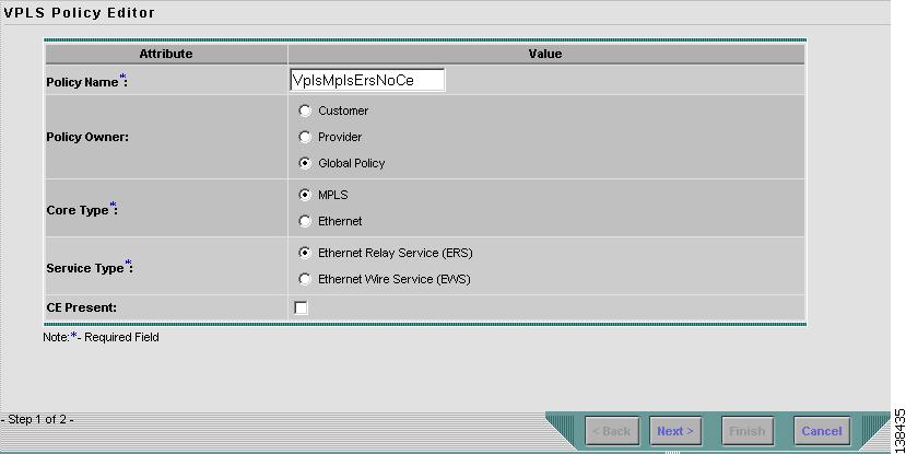
Defining an MPLS/ERS Policy without a CE
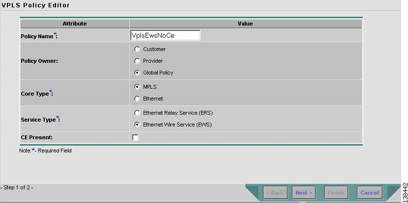
This section describes defining a VPLS policy with an MPLS core type and an ERS service type without a CE present. Figure 8-7 is an example of the first page of this policy.
Figure 8-7 MPLS/ERS Policy without a CE
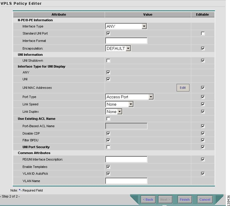
Step 1
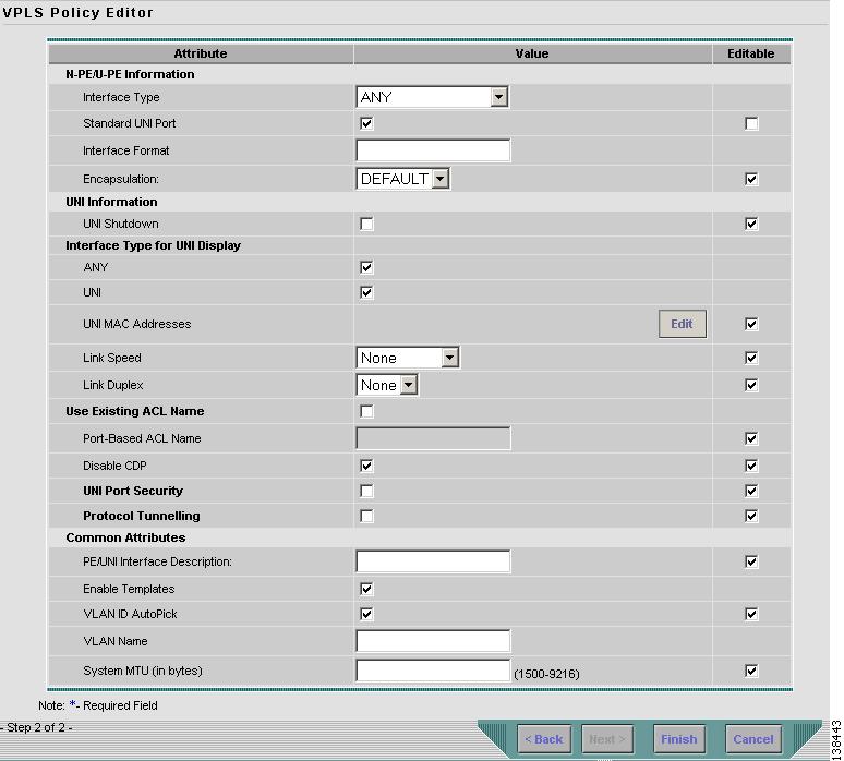
Click Next. The window in Figure 8-8 appears.
The Editable check box gives you the option of making a field editable. If you select the Editable check box, the service operator who is using this VPLS policy can modify the editable parameter during VPLS service request creation.
Figure 8-8 MPLS/ERS without a CE Policy Attributes
Step 2
Choose an Interface Type from the drop-down list.
You can choose to select a particular interface on a N-PE, U-PE, or PE-AGG interface based on the service provider's POP design. The interfaces are:
•
ANY (Any interface can be chosen.)
•
Port-Channel (A bundle of ports that share the same characteristics—this gives the service provider the ability to aggregate bandwidth and protection.)
•
Ethernet
•
FastEthernet
•
GE-WAN
•
GigabitEthernet
•
TenGigabitEthernet
The value defined here functions as a filter to restrict the interface types an operator can see during VPLS service request creation. If defined as ANY, the operator can see all interface types.
Step 3
Select the Standard UNI Port check box to enable port security. This is the default. When you deselect the check box, the port is treated as an uplink with no security features, and the window dynamically changes to eliminate items related to port security.
Step 4
Enter an Interface Format as the slot number/port number for the CE interface (for example, 1/0 indicates that the interface is located at slot 1, port 0).
This is especially useful to specify here if you know that the link will always go through a particular interface's slot/port location on all or most of the network devices in the service.
Step 5
Choose a CE Encapsulation type. The choices are:
•
DOT1Q
•
DEFAULT
If DEFAULT is the CE encapsulation type, ISC shows another field for the UNI port type.
Step 6
Check UNI Shutdown box if you want to leave the UNI port shut during service activation, for example, when the service provider wants to deploy a service in the network but wants to activate it at a later time.
Step 7
Select the ANY check box to display all interface types as choices for the UNI interface (when creating service requests based on this policy). This check box is checked by default.
Step 8
Select the UNI check box to display all interfaces defined as type UNI as choices for the UNI interface (when creating service requests based on this policy). This check box is checked by default.
Step 9
Choose a Port Type. The choices are:
•
Access Port
•
Trunk with Native VLAN
Step 10
Enter a Link Speed of none, 10, 100, 1000, or auto.
Step 11
Enter a Line Duplex of none, full, half, or auto.
Step 12
Select the Use Existing ACL Name check box if you want assign your own named access list to the port. By default, this check box is not selected and ISC automatically assigns a MAC-based ACL on the customer facing UNI port, based on values you enter in UNI MAC addresses (below).
Step 13
Enter a Port-Based ACL Name (if you selected the Use Existing ACL Name check box, as mentioned in the previous step).
Step 14
Enter one or more Ethernet MAC addresses in UNI MAC addresses. This selection is present only if you deselect the Use Existing ACL Name check box. Click the Edit button to bring up a pop-up window in which you enter MAC addresses to be allowed or denied on the port. You can also specify a range of addresses by setting a base MAC address and a filtered MAC address.
Step 15
Select the Disable CDP check box if you want to disable the Cisco Discover Protocol (CDP) on the UNI port.
Step 16
Select the Filter BPDU check box to specify that the UNI port should not process Layer 2 Bridge Protocol Data Units (BPDUs).
Step 17
Select the UNI Port Security check box (see Figure 8-9) if you to want to provision port security-related CLIs to the UNI port by controlling the MAC addresses that are allowed to go through the interface.
a.
For Maximum Number of MAC address, enter the number of MAC addresses allowed for port security.
b.
For Aging, enter the length of time the MAC address can stay on the port security table.
c.
For Violation Action, choose what action will occur when a port security violation is detected:
•
PROTECT—Drops packets with unknown source addresses until a sufficient number of secure MAC addresses are removed to drop below the maximum value.
•
RESTRICT—Drops packets with unknown source addresses until a sufficient number of secure MAC addresses are removed to drop below the maximum value and causes the Security Violation counter to increment.
•
SHUTDOWN—Puts the interface into the error-disabled state immediately and sends an SNMP trap notification.
d.
In the Secure MAC Addresses field, enter one or more Ethernet MAC addresses.
Figure 8-9 UNI Port Security
Step 18
Select the Enable Storm Control check box (see Figure 8-10) to help prevent the UNI port from being disrupted by a broadcast, multicast or unicast storm. Enter a threshold value for each type of traffic. The value, which can be specified to two significant digits, represents the percentage of the total available bandwidth of the port. If the threshold of a traffic type is reached, further traffic of that type is suppressed until the incoming traffic falls below the threshold level.
Figure 8-10 Enable Storm Control
Step 19
In the PE/UNI Interface Description field, enter an optional description, for example Customer-B ERS Service.
Step 20
Select the Enable Templates check box if you want to download free-format CLIs to a device. If you enable templates, you can create templates and data files to push down to the routers commands that are not normally supported by ISC. See Cisco IP Solution Center Infrastructure Reference, 4.1 for more information about template management.
Step 21
Select the VLANID AutoPick check box if you want ISC to choose a VLAN ID. If you do not select this check box, you will be prompted to provide the VLAN in a Provider VLAN ID field during service activation.
Step 22
Enter a VLAN NAME (optional) to specify a name to describe the VLAN. The name must be one token (no spaces allowed.) The limit for the VLAN name is 32 characters. The name has to be unique. Two VLANs cannot share the same name.
Step 23
Click Finish.
Note
The VC ID is mapped from the VPN ID. By default, ISC will "auto pick" this value. However, you can set this manually, if desired. This is done by editing the associated VPN configuration. The Edit VPN window has an Enable VPLS check box. When you check this box, you can manually enter a VPN ID in a field provided. For more information on creating and modifying VPNs, see Cisco IP Solution Center Infrastructure Reference, 4.1.
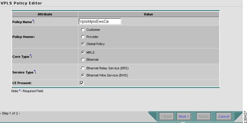
Defining an MPLS/EWS Policy with a CE
This section describes defining a VPLS policy with an MPLS core type and an EWS service type with CE present. Figure 8-11 is an example of the first page of this policy.
Figure 8-11 MPLS/EWS Policy with a CE
Perform the following steps.
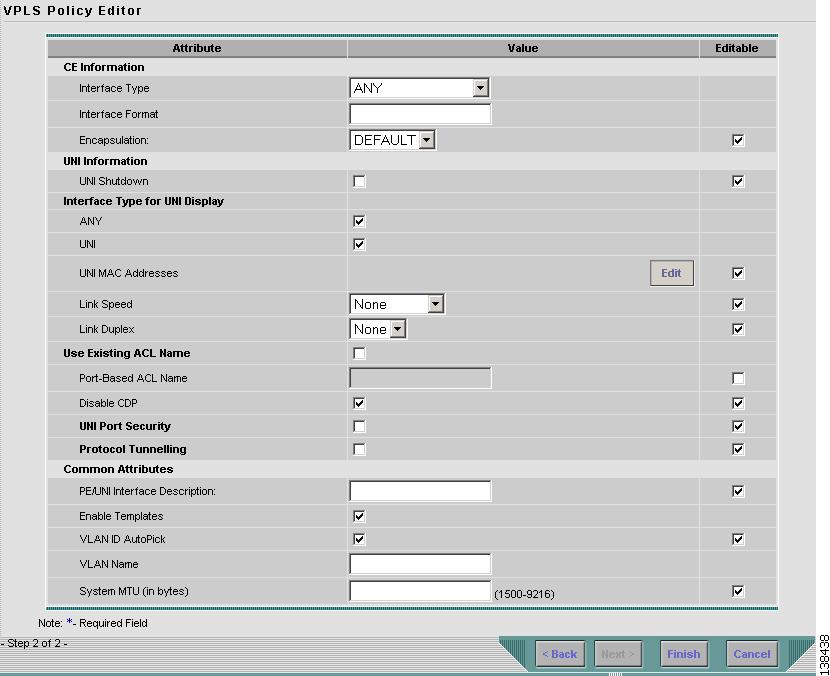
Step 1
Click Next. The window in Figure 8-12 appears.
The Editable check box gives you the option of making a field editable. If you select the Editable check box, the service operator who is using this VPLS policy can modify the editable parameter during VPLS service request creation.
Figure 8-12 MPLS/EWS with a CE Policy Attributes
Step 2
Choose an Interface Type from the drop-down list.
You can choose to select a particular interface on a CE, N-PE, U-PE, or PE-AGG interface based on the service provider's POP design. The interfaces are:
•
ANY (Any interface can be chosen.)
•
Port-Channel (A bundle of ports that share the same characteristics—this gives the service provider the ability to aggregate bandwidth and protection.)
•
Ethernet
•
FastEthernet
•
GE-WAN
•
GigabitEthernet
•
TenGigabitEthernet
The value defined here functions as a filter to restrict the interface types an operator can see during VPLS service request creation. If defined as ANY, the operator can see all interface types.
Step 3
Enter an Interface Format as the slot number/port number for the CE interface (for example, 1/0 indicates that the interface is located at slot 1, port 0).
This is especially useful to specify here if you know that the link will always go through a particular interface's slot/port location on all or most of the network devices in the service.
Step 4
Choose a CE Encapsulation type. The choices are:
•
DOT1Q
•
DEFAULT
Step 5
Select the UNI Shutdown check box if you want to leave the UNI port shut during service activation, for example, when the service provider wants to deploy a service in the network but wants to activate it at a later time.
Step 6
Select the ANY check box to display all interface types as choices for the UNI interface (when creating service requests based on this policy). This check box is checked by default.
Step 7
Select the UNI check box to display all interfaces defined as type UNI as choices for the UNI interface (when creating service requests based on this policy). This check box is checked by default.
Step 8
Enter a Link Speed of none, 10, 100, 1000, or auto.
Step 9
Enter a Line Duplex of none, full, half, or auto.
Step 10
Select the Use Existing ACL Name check box if you want assign your own named access list to the port. By default, this check box is not selected and ISC automatically assigns a MAC-based ACL on the customer facing UNI port, based on values you enter in UNI MAC addresses (below).
Step 11
Enter a Port-Based ACL Name (if you selected the Use Existing ACL Name check box, as mentioned in the previous step).
Step 12
Enter one or more Ethernet MAC addresses in UNI MAC addresses. This selection is present only if you deselect the Use Existing ACL Name check box. Click the Edit button to bring up a pop-up window in which you enter MAC addresses to be allowed or denied on the port. You can also specify a range of addresses by setting a base MAC address and a filtered MAC address.
Step 13
Select the Disable CDP check box if you want to disable the Cisco Discover Protocol (CDP) on the UNI port.
Step 14
Select the UNI Port Security check box (see Figure 8-13) if you to want to provision port security-related CLIs to the UNI port by controlling the MAC addresses that are allowed to go through the interface.
a.
For Maximum Number of MAC address, enter the number of MAC addresses allowed for port security.
b.
For Aging, enter the length of time the MAC address can stay on the port security table.
c.
For Violation Action, choose what action will occur when a port security violation is detected:
•
PROTECT—Drops packets with unknown source addresses until a sufficient number of secure MAC addresses are removed to drop below the maximum value.
•
RESTRICT—Drops packets with unknown source addresses until a sufficient number of secure MAC addresses are removed to drop below the maximum value and causes the Security Violation counter to increment.
•
SHUTDOWN—Puts the interface into the error-disabled state immediately and sends an SNMP trap notification.
d.
In the Secure MAC Addresses field, enter one or more Ethernet MAC addresses.
Figure 8-13 UNI Port Security
Step 15
Select the Enable Storm Control check box (see Figure 8-14) to help prevent the UNI port from being disrupted by a broadcast, multicast or unicast storm. Enter a threshold value for each type of traffic. The value, which can be specified to two significant digits, represents the percentage of the total available bandwidth of the port. If the threshold of a traffic type is reached, further traffic of that type is suppressed until the incoming traffic falls below the threshold level.
Figure 8-14 Enable Storm Control
Step 16
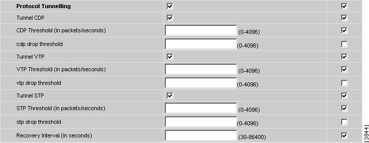
Select the Protocol Tunnelling check box (see Figure 8-15) if you want to define the Layer 2 Bridge Protocol Data Unit (BPDU) frames that can be tunneled over the core to the other end.
Figure 8-15 Protocol Tunnelling
For each protocol that you check, enter the shutdown threshold and drop threshold for that protocol:
a.
Tunnel CDP—Enable Layer 2 tunnelling on Cisco Discover Protocol (CDP).
b.
CDP Threshold—Enter the number of packets per second to be received before the interface is shut down.
c.
cdp drop threshold—Enter the number of packets per second to be received at which point the interface will start dropping CDP packets.
d.
Tunnel VTP—Enable Layer 2 tunnelling on VLAN Trunk Protocol (VTP).
e.
VTP threshold—Enter the number of packets per second to be received before the interface is shut down.
f.
vtp drop threshold—Enter the number of packets per second to be received at which point the interface will start dropping VTP packets.
g.
Tunnel STP—Enable Layer 2 tunnelling on Spanning Tree Protocol (STP).
h.
STP Threshold—Enter the number of packets per second to be received before the interface is shut down.
i.
stp drop threshold—Enter the number of packets per second to be received at which point the interface will start dropping STP packets.
j.
Recovery Interval—Enter the amount of time, in seconds, to wait before recovering a UNI port.
Step 17
In the PE/UNI Interface Description field, enter an optional description, for example Customer-B EWS Service.
Step 18
Select the Enable Templates check box if you want to download free-format CLIs to a device. If you enable templates, you can create templates and data files to push down to the routers commands that are not normally supported by ISC. See Cisco IP Solution Center Infrastructure Reference, 4.1 for more information about template management.
Step 19
Select the VLANID AutoPick check box if you want ISC to choose a VLAN ID. If you do not select this check box, you will be prompted to provide the VLAN in a Provider VLAN ID field during service activation.
Step 20
Enter a VLAN NAME (optional) to specify a name to describe the VLAN. The name must be one token (no spaces allowed.) The limit for the VLAN name is 32 characters. The name has to be unique. Two VLANs cannot share the same name.
Step 21
Enter the System MTU in bytes.
Step 22
Click Finish.
Note
The VC ID is mapped from the VPN ID. By default, ISC will "auto pick" this value. However, you can set this manually, if desired. This is done by editing the associated VPN configuration. The Edit VPN window has an Enable VPLS check box. When you check this box, you can manually enter a VPN ID in a field provided. For more information on creating and modifying VPNs, see Cisco IP Solution Center Infrastructure Reference, 4.1.
Defining an MPLS/EWS Policy without a CE
This section describes defining a VPLS policy with an MPLS core type and an EWS service type without a CE present. Figure 8-16 is an example of the first page of this policy.
Figure 8-16 MPLS/EWS Policy without a CE
Step 1
Click Next. The window in Figure 8-17 appears.
The Editable check box gives you the option of making a field editable. If you select Editable check box, the service operator who is using this VPLS policy can modify the editable parameter during VPLS service request creation.
Figure 8-17 MPLS/EWS without a CE Policy Attributes
Step 2
Choose an Interface Type from the drop-down list.
You can choose to select a particular interface on a N-PE, U-PE, or PE-AGG interface based on the service provider's POP design. The interfaces are:
•
ANY (Any interface can be chosen.)
•
Port-Channel (A bundle of ports that share the same characteristics—this gives the service provider the ability to aggregate bandwidth and protection.)
•
Ethernet
•
FastEthernet
•
GE-WAN
•
GigabitEthernet
•
TenGigabitEthernet
The value defined here functions as a filter to restrict the interface types an operator can see during VPLS service request creation. If defined as ANY, the operator can see all interface types.
Step 3
Select the Standard UNI Port check box to enable port security. This is the default. When you deselect the check box, the port is treated as an uplink with no security features, and the window dynamically changes to eliminate items related to port security.
Step 4
Enter an Interface Format as the slot number/port number for the PE interface (for example, 1/0 indicates that the interface is located at slot 1, port 0).
This is especially useful to specify here if you know that the link will always go through a particular interface's slot/port location on all or most of the network devices in the service.
Step 5
Choose an N-PE/U-PE Encapsulation type. The choices are:
•
DOT1Q
•
DEFAULT
Step 6
Select the UNI Shutdown check box if you want to leave the UNI port shut during service activation, for example, when the service provider wants to deploy a service in the network but wants to activate it at a later time.
Step 7
Select the ANY check box to display all interface types as choices for the UNI interface (when creating service requests based on this policy). This check box is checked by default.
Step 8
Select the UNI check box to display all interfaces defined as type UNI as choices for the UNI interface (when creating service requests based on this policy). This check box is checked by default.
Step 9
Enter a Link Speed of none, 10, 100, 1000, or auto.
Step 10
Enter a Line Duplex of none, full, half, or auto.
Step 11
Select the Use Existing ACL Name check box if you want assign your own named access list to the port. By default, this check box is not selected and ISC automatically assigns a MAC-based ACL on the customer facing UNI port, based on values you enter in UNI MAC addresses (below).
Step 12
Enter a Port-Based ACL Name (if you selected the Use Existing ACL Name check box, as mentioned in the previous step).
Step 13
Enter one or more Ethernet MAC addresses in UNI MAC addresses. This selection is present only if you deselect the Use Existing ACL Name check box. Click the Edit button to bring up a pop-up window in which you enter MAC addresses to be allowed or denied on the port. You can also specify a range of addresses by setting a base MAC address and a filtered MAC address.
Step 14
Select the Disable CDP check box if you want to disable the Cisco Discover Protocol (CDP) on the UNI port.
Step 15
Select the UNI Port Security check box (see Figure 8-18) if you to want to provision port security-related CLIs to the UNI port by controlling the MAC addresses that are allowed to go through the interface.
a.
For Maximum Number of MAC address, enter the number of MAC addresses allowed for port security.
b.
For Aging, enter the length of time the MAC address can stay on the port security table.
c.
For Violation Action, choose what action will occur when a port security violation is detected:
•
PROTECT—Drops packets with unknown source addresses until a sufficient number of secure MAC addresses are removed to drop below the maximum value.
•
RESTRICT—Drops packets with unknown source addresses until a sufficient number of secure MAC addresses are removed to drop below the maximum value and causes the Security Violation counter to increment.
•
SHUTDOWN—Puts the interface into the error-disabled state immediately and sends an SNMP trap notification.
d.
In the Secure MAC Addresses field, enter one or more Ethernet MAC addresses.
Figure 8-18 UNI Port Security
Step 16
Select the Enable Storm Control check box (see Figure 8-19) to help prevent the UNI port from being disrupted by a broadcast, multicast or unicast storm. Enter a threshold value for each type of traffic. The value, which can be specified to two significant digits, represents the percentage of the total available bandwidth of the port. If the threshold of a traffic type is reached, further traffic of that type is suppressed until the incoming traffic falls below the threshold level.
Figure 8-19 Enable Storm Control
Step 17
Select the Protocol Tunnelling check box (see Figure 8-20) if you want to define the Layer 2 Bridge Protocol Data Unit (BPDU) frames that can be tunneled over the core to the other end.
Figure 8-20 Protocol Tunnelling
For each protocol that you check, enter the shutdown threshold and drop threshold for that protocol:
a.
Tunnel CDP—Enable Layer 2 tunnelling on Cisco Discover Protocol (CDP).
b.
CDP Threshold—Enter the number of packets per second to be received before the interface is shut down.
c.
cdp drop threshold—Enter the number of packets per second to be received at which point the interface will start dropping CDP packets.
d.
Tunnel VTP—Enable Layer 2 tunnelling on VLAN Trunk Protocol (VTP).
e.
VTP threshold—Enter the number of packets per second to be received before the interface is shut down.
f.
vtp drop threshold—Enter the number of packets per second to be received at which point the interface will start dropping VTP packets.
g.
Tunnel STP—Enable Layer 2 tunnelling on Spanning Tree Protocol (STP).
h.
STP Threshold—Enter the number of packets per second to be received before the interface is shut down.
i.
stp drop threshold—Enter the number of packets per second to be received at which point the interface will start dropping STP packets.
j.
Recovery Interval—Enter the amount of time, in seconds, to wait before recovering a UNI port.
Step 18
In the PE/UNI Interface Description field, enter an optional description, for example Customer-B EWS Service.
Step 19
Check the Enable Templates box if you want to download free-format CLIs to a device. If you enable templates, you can create templates and data files to push down to the routers commands that are not normally supported by ISC. See Cisco IP Solution Center Infrastructure Reference, 4.1 for more information about template management.
Step 20
Select the VLANID AutoPick check box if you want ISC to choose a VLAN ID. If you do not select this check box, you will be prompted to provide the VLAN in a Provider VLAN ID field during service activation.
Step 21
Enter a VLAN NAME (optional) to specify a name to describe the VLAN. The name must be one token (no spaces allowed.) The limit for the VLAN name is 32 characters. The name has to be unique. Two VLANs cannot share the same name.
Step 22
Enter the System MTU in bytes.
Step 23
Click Finish.
Note
The VC ID is mapped from the VPN ID. By default, ISC will "auto pick" this value. However, you can set this manually, if desired. This is done by editing the associated VPN configuration. The Edit VPN window has an Enable VPLS check box. When you check this box, you can manually enter a VPN ID in a field provided. For more information on creating and modifying VPNs, see Cisco IP Solution Center Infrastructure Reference, 4.1.
Defining an Ethernet/ERS Policy with a CE
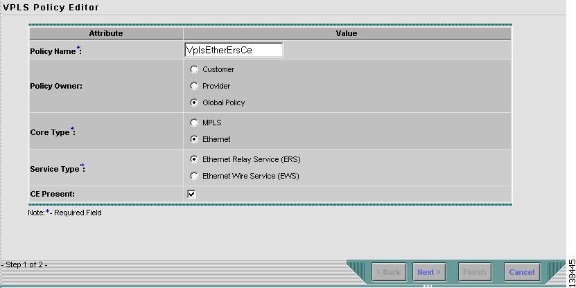
This section describes defining a VPLS policy with an Ethernet core type and an ERS service type with CE present. Figure 8-21 is an example of the first page of this policy.
Figure 8-21 Ethernet/ERS Policy with a CE
Perform the following steps.
Step 1
Click Next. The window in Figure 8-22 appears.
The Editable check box gives you the option of making a field editable. If you select the Editable check box, the service operator who is using this VPLS policy can modify the editable parameter during VPLS service request creation.
Figure 8-22 Ethernet ERS with a CE Policy Attributes
Step 2
Choose an Interface Type from the drop-down list.
You can choose to select a particular interface on a CE, N-PE, U-PE, or PE-AGG interface based on the service provider's POP design. The interfaces are:
•
ANY (Any interface can be chosen.)
•
Port-Channel (A bundle of ports that share the same characteristics—this gives the service provider the ability to aggregate bandwidth and protection.)
•
Ethernet
•
FastEthernet
•
GE-WAN
•
GigabitEthernet
•
TenGigabitEthernet
The value defined here functions as a filter to restrict the interface types an operator can see during VPLS service request creation. If defined as ANY, the operator can see all interface types.
Step 3
Enter an Interface Format as the slot number/port number for the CE interface (for example, 1/0 indicates that the interface is located at slot 1, port 0).
This is especially useful to specify here if you know that the link will always go through a particular interface's slot/port location on all or most of the network devices in the service.
Step 4
Choose a CE Encapsulation type. The choices are:
•
DOT1Q
•
DEFAULT
If DEFAULT is the CE encapsulation type, ISC shows another field for the UNI port type.
Step 5
Select the UNI Shutdown check box if you want to leave the UNI port shut during service activation, for example, when the service provider wants to deploy a service in the network but wants to activate it at a later time.
Step 6
Select the ANY check box to display all interface types as choices for the UNI interface (when creating service requests based on this policy). This check box is checked by default.
Step 7
Select the UNI check box to display all interfaces defined as type UNI as choices for the UNI interface (when creating service requests based on this policy). This check box is checked by default.
Step 8
Choose a Port Type. The choices are:
•
Access Port
•
Trunk with Native VLAN
Step 9
Enter a Link Speed of none, 10, 100, 1000, or auto.
Step 10
Enter a Line Duplex of none, full, half, or auto.
Step 11
Select the Use Existing ACL Name check box if you want assign your own named access list to the port. By default, this check box is not selected and ISC automatically assigns a MAC-based ACL on the customer facing UNI port, based on values you enter in UNI MAC addresses (below).
Step 12
Enter a Port-Based ACL Name (if you selected the Use Existing ACL Name check box, as mentioned in the previous step).
Step 13
Enter one or more Ethernet MAC addresses in UNI MAC addresses. This selection is present only if you deselect the Use Existing ACL Name check box. Click the Edit button to bring up a pop-up window in which you enter MAC addresses to be allowed or denied on the port. You can also specify a range of addresses by setting a base MAC address and a filtered MAC address.
Step 14
Select the Disable CDP check box if you want to disable the Cisco Discover Protocol (CDP) on the UNI port.
Step 15
Select the Filter BPDU check box to specify that the UNI port should not process Layer 2 Bridge Protocol Data Units (BPDUs).
Step 16
Select the UNI Port Security check box (see Figure 8-23) if you to want to provision port security-related CLIs to the UNI port by controlling the MAC addresses that are allowed to go through the interface.
a.
For Maximum Number of MAC address, enter the number of MAC addresses allowed for port security.
b.
For Aging, enter the length of time the MAC address can stay on the port security table.
c.
For Violation Action, choose what action will occur when a port security violation is detected:
•
PROTECT—Drops packets with unknown source addresses until a sufficient number of secure MAC addresses are removed to drop below the maximum value.
•
RESTRICT—Drops packets with unknown source addresses until a sufficient number of secure MAC addresses are removed to drop below the maximum value and causes the Security Violation counter to increment.
•
SHUTDOWN—Puts the interface into the error-disabled state immediately and sends an SNMP trap notification.
d.
In the Secure MAC Addresses field, enter one or more Ethernet MAC addresses.
Figure 8-23 UNI Port Security
Step 17
Select the Enable Storm Control check box (see Figure 8-23) to help prevent the UNI port from being disrupted by a broadcast, multicast or unicast storm. Enter a threshold value for each type of traffic. The value, which can be specified to two significant digits, represents the percentage of the total available bandwidth of the port. If the threshold of a traffic type is reached, further traffic of that type is suppressed until the incoming traffic falls below the threshold level.
Figure 8-24 Enable Storm Control
Step 18
In the PE/UNI Interface Description field, enter an optional description, for example Customer-B ERS Service.
Step 19
Select the Enable Templates check box if you want to download free-format CLIs to a device. If you enable templates, you can create templates and data files to push down to the routers commands that are not normally supported by ISC. See Cisco IP Solution Center Infrastructure Reference, 4.1 for more information about template management.
Step 20
Select the VLANID AutoPick check box if you want ISC to choose a VLAN ID. If you do not select this check box, you will be prompted to provide the VLAN in a Provider VLAN ID field during service activation.
Step 21
Enter a VLAN NAME (optional) to specify a name to describe the VLAN. The name must be one token (no spaces allowed.) The limit for the VLAN name is 32 characters. The name has to be unique. Two VLANs cannot share the same name.
Step 22
Click Finish.
Note
The VC ID is mapped from the VPN ID. By default, ISC will "auto pick" this value. However, you can set this manually, if desired. This is done by editing the associated VPN configuration. The Edit VPN window has an Enable VPLS check box. When you check this box, you can manually enter a VPN ID in a field provided. For more information on creating and modifying VPNs, see Cisco IP Solution Center Infrastructure Reference, 4.1.
Defining an Ethernet/ERS Policy without a CE
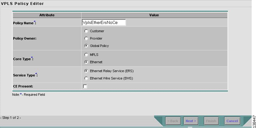
This section describes defining a VPLS policy with an Ethernet core type and an ERS service type without a CE present. Figure 8-25 is an example of the first page of this policy.
Figure 8-25 Ethernet/ERS Policy without a CE
Perform the following steps.
Step 1
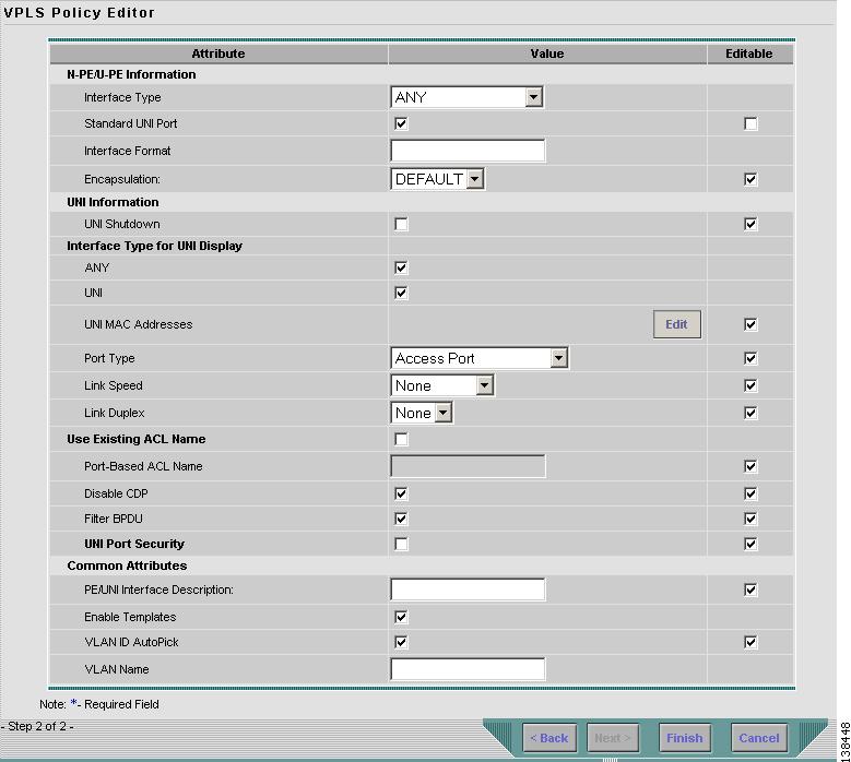
Click Next. The window in Figure 8-26 appears.
The Editable check box gives you the option of making a field editable. If you select the Editable check box, the service operator who is using this VPLS policy can modify the editable parameter during VPLS service request creation.
Figure 8-26 Ethernet/ERS without a CE Policy Attributes
Step 2
Choose an Interface Type from the drop-down list.
You can choose to select a particular interface on a CE, N-PE, U-PE, or PE-AGG interface based on the service provider's POP design. The interfaces are:
•
ANY (Any interface can be chosen.)
•
Port-Channel (A bundle of ports that share the same characteristics—this gives the service provider the ability to aggregate bandwidth and protection.)
•
Ethernet
•
FastEthernet
•
GE-WAN
•
GigabitEthernet
•
TenGigabitEthernet
The value defined here functions as a filter to restrict the interface types an operator can see during VPLS service request creation. If defined as ANY, the operator can see all interface types.
Step 3
Select the Standard UNI Port check box to enable port security. This is the default. When you deselect the check box, the port is treated as an uplink with no security features, and the window dynamically changes to eliminate items related to port security.
Step 4
Enter an Interface Format as the slot number/port number for the CE interface (for example, 1/0 indicates that the interface is located at slot 1, port 0).
This is especially useful to specify here if you know that the link will always go through a particular interface's slot/port location on all or most of the network devices in the service.
Step 5
Choose a CE Encapsulation type. The choices are:
•
DOT1Q
•
DEFAULT
If DEFAULT is the CE encapsulation type, ISC shows another field for the UNI port type.
Step 6
Select the UNI Shutdown check box if you want to leave the UNI port shut during service activation, for example, when the service provider wants to deploy a service in the network but wants to activate it at a later time.
Step 7
Select the ANY check box to display all interface types as choices for the UNI interface (when creating service requests based on this policy). This check box is checked by default.
Step 8
Select the UNI check box to display all interfaces defined as type UNI as choices for the UNI interface (when creating service requests based on this policy). This check box is checked by default.
Step 9
Choose a Port Type. The choices are:
•
Access Port
•
Trunk with Native VLAN
Step 10
Enter a Link Speed of none, 10, 100, 1000, or auto.
Step 11
Enter a Line Duplex of none, full, half, or auto.
Step 12
Select the Use Existing ACL Name check box if you want assign your own named access list to the port. By default, this check box is not selected and ISC automatically assigns a MAC-based ACL on the customer facing UNI port, based on values you enter in UNI MAC addresses (below).
Step 13
Enter a Port-Based ACL Name (if you selected the Use Existing ACL Name check box, as mentioned in the previous step).
Step 14
Enter one or more Ethernet MAC addresses in UNI MAC addresses. This selection is present only if you deselect the Use Existing ACL Name check box. Click the Edit button to bring up a pop-up window in which you enter MAC addresses to be allowed or denied on the port. You can also specify a range of addresses by setting a base MAC address and a filtered MAC address.
Step 15
Select the Disable CDP check box if you want to disable the Cisco Discover Protocol (CDP) on the UNI port.
Step 16
Select the Filter BPDU check box to specify that the UNI port should not process Layer 2 Bridge Protocol Data Units (BPDUs).
Step 17
Select the UNI Port Security check box (see Figure 8-27) if you to want to provision port security-related CLIs to the UNI port by controlling the MAC addresses that are allowed to go through the interface.
a.
For Maximum Number of MAC address, enter the number of MAC addresses allowed for port security.
b.
For Aging, enter the length of time the MAC address can stay on the port security table.
c.
For Violation Action, choose what action will occur when a port security violation is detected:
•
PROTECT—Drops packets with unknown source addresses until a sufficient number of secure MAC addresses are removed to drop below the maximum value.
•
RESTRICT—Drops packets with unknown source addresses until a sufficient number of secure MAC addresses are removed to drop below the maximum value and causes the Security Violation counter to increment.
•
SHUTDOWN—Puts the interface into the error-disabled state immediately and sends an SNMP trap notification.
d.
In the Secure MAC Addresses field, enter one or more Ethernet MAC addresses.
Figure 8-27 UNI Port Security
Step 18
Select the Enable Storm Control check box (see Figure 8-28) to help prevent the UNI port from being disrupted by a broadcast, multicast or unicast storm. Enter a threshold value for each type of traffic. The value, which can be specified to two significant digits, represents the percentage of the total available bandwidth of the port. If the threshold of a traffic type is reached, further traffic of that type is suppressed until the incoming traffic falls below the threshold level.
Figure 8-28 Enable Storm Control
Step 19
In the PE/UNI Interface Description field, enter an optional description, for example Customer-B ERS Service.
Step 20
Select the Enable Templates check box if you want to download free-format CLIs to a device. If you enable templates, you can create templates and data files to push down to the routers commands that are not normally supported by ISC. See Cisco IP Solution Center Infrastructure Reference, 4.1 for more information about template management.
Step 21
Select the VLANID AutoPick check box if you want ISC to choose a VLAN ID. If you do not select this check box, you will be prompted to provide the VLAN in a Provider VLAN ID field during service activation.
Step 22
Enter a VLAN NAME (optional) to specify a name to describe the VLAN. The name must be one token (no spaces allowed.) The limit for the VLAN name is 32 characters. The name has to be unique. Two VLANs cannot share the same name.
Step 23
Click Finish.
Note
The VC ID is mapped from the VPN ID. By default, ISC will "auto pick" this value. However, you can set this manually, if desired. This is done by editing the associated VPN configuration. The Edit VPN window has an Enable VPLS check box. When you check this box, you can manually enter a VPN ID in a field provided. For more information on creating and modifying VPNs, see Cisco IP Solution Center Infrastructure Reference, 4.1.
Defining an Ethernet/EWS Policy with a CE
This section describes defining a VPLS policy with an Ethernet core type and an ERS service type with a CE present. Figure 8-29 is an example of the first page of this policy.
Figure 8-29 Ethernet/EWS Policy with CE Present
Perform the following steps.
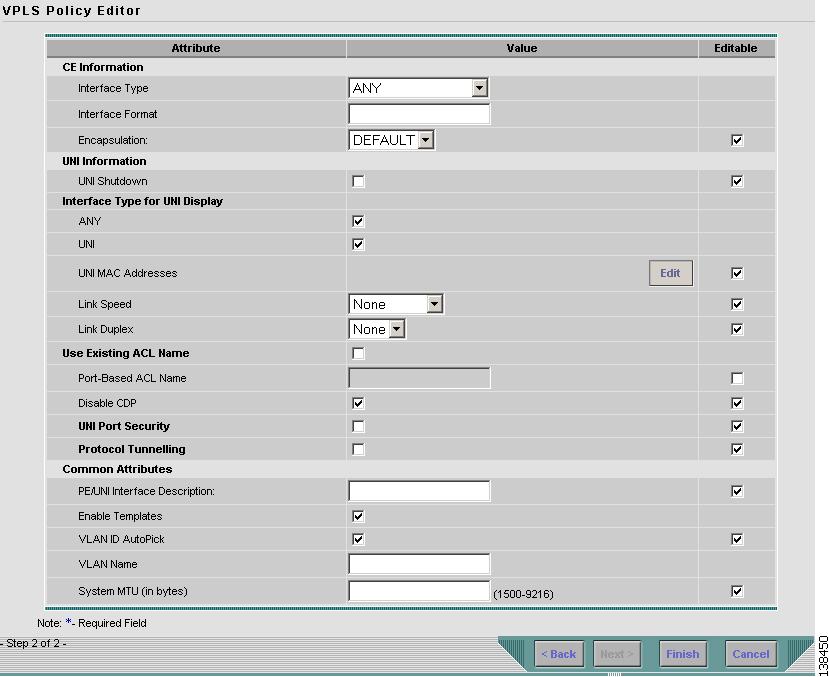
Step 1
Click Next. The window in Figure 8-30 appears.
The Editable check box gives you the option of making a field editable. If you select the Editable check box, the service operator who is using this VPLS policy can modify the editable parameter during VPLS service request creation.
Figure 8-30 Ethernet/EWS with a CE Policy Attributes
Step 2
Choose an Interface Type from the drop-down list.
You can choose to select a particular interface on a CE, N-PE, U-PE, or PE-AGG interface based on the service provider's POP design. The interfaces are:
•
ANY (Any interface can be chosen.)
•
Port-Channel (A bundle of ports that share the same characteristics—this gives the service provider the ability to aggregate bandwidth and protection.)
•
Ethernet
•
FastEthernet
•
GE-WAN
•
GigabitEthernet
•
TenGigabitEthernet
The value defined here functions as a filter to restrict the interface types an operator can see during VPLS service request creation. If defined as ANY, the operator can see all interface types.
Step 3
Enter an Interface Format as the slot number/port number for the CE interface (for example, 1/0 indicates that the interface is located at slot 1, port 0).
This is especially useful to specify here if you know that the link will always go through a particular interface's slot/port location on all or most of the network devices in the service.
Step 4
Choose a CE Encapsulation type. The choices are:
•
DOT1Q
•
DEFAULT
Step 5
Select the UNI Shutdown check box if you want to leave the UNI port shut during service activation, for example, when the service provider wants to deploy a service in the network but wants to activate it at a later time.
Step 6
Select the ANY check box to display all interface types as choices for the UNI interface (when creating service requests based on this policy). This check box is checked by default.
Step 7
Select the UNI check box to display all interfaces defined as type UNI as choices for the UNI interface (when creating service requests based on this policy). This check box is checked by default.
Step 8
Enter a Link Speed of none, 10, 100, 1000, or auto.
Step 9
Enter a Line Duplex of none, full, half, or auto.
Step 10
Select the Use Existing ACL Name check box if you want assign your own named access list to the port. By default, this is not selected and ISC automatically assigns a MAC-based ACL on the customer facing UNI port, based on values you enter in UNI MAC addresses (below).
Step 11
Enter a Port-Based ACL Name (if you selected the Use Existing ACL Name check box, as mentioned in the previous step).
Step 12
Enter one or more Ethernet MAC addresses in UNI MAC addresses. This selection is present only if you deselect the Use Existing ACL Name check box. Click the Edit button to bring up a pop-up window in which you enter MAC addresses to be allowed or denied on the port. You can also specify a range of addresses by setting a base MAC address and a filtered MAC address.
Step 13
Select the Disable CDP check box if you want to disable the Cisco Discover Protocol (CDP) on the UNI port.
Step 14
Select the UNI Port Security check box (see Figure 8-31) if you to want to provision port security-related CLIs to the UNI port by controlling the MAC addresses that are allowed to go through the interface.
a.
For Maximum Number of MAC address, enter the number of MAC addresses allowed for port security.
b.
For Aging, enter the length of time the MAC address can stay on the port security table.
c.
For Violation Action, choose what action will occur when a port security violation is detected:
•
PROTECT—Drops packets with unknown source addresses until a sufficient number of secure MAC addresses are removed to drop below the maximum value.
•
RESTRICT—Drops packets with unknown source addresses until a sufficient number of secure MAC addresses are removed to drop below the maximum value and causes the Security Violation counter to increment.
•
SHUTDOWN—Puts the interface into the error-disabled state immediately and sends an SNMP trap notification.
d.
In the Secure MAC Addresses field, enter one or more Ethernet MAC addresses.
Figure 8-31 UNI Port Security
Step 15
Select the Enable Storm Control check box (see Figure 8-32) to help prevent the UNI port from being disrupted by a broadcast, multicast or unicast storm. Enter a threshold value for each type of traffic. The value, which can be specified to two significant digits, represents the percentage of the total available bandwidth of the port. If the threshold of a traffic type is reached, further traffic of that type is suppressed until the incoming traffic falls below the threshold level.
Figure 8-32 Enable Storm Control
Step 16
Select the Protocol Tunnelling check box (see Figure 8-33) if you want to define the Layer 2 Bridge Protocol Data Unit (BPDU) frames that can be tunneled over the core to the other end.
Figure 8-33 Protocol Tunnelling
For each protocol that you check, enter the shutdown threshold and drop threshold for that protocol:
a.
Tunnel CDP—Enable Layer 2 tunnelling on Cisco Discover Protocol (CDP).
b.
CDP Threshold—Enter the number of packets per second to be received before the interface is shut down.
c.
cdp drop threshold—Enter the number of packets per second to be received at which point the interface will start dropping CDP packets.
d.
Tunnel VTP—Enable Layer 2 tunnelling on VLAN Trunk Protocol (VTP).
e.
VTP threshold—Enter the number of packets per second to be received before the interface is shut down.
f.
vtp drop threshold—Enter the number of packets per second to be received at which point the interface will start dropping VTP packets.
g.
Tunnel STP—Enable Layer 2 tunnelling on Spanning Tree Protocol (STP).
h.
STP Threshold—Enter the number of packets per second to be received before the interface is shut down.
i.
stp drop threshold—Enter the number of packets per second to be received at which point the interface will start dropping STP packets.
j.
Recovery Interval—Enter the amount of time, in seconds, to wait before recovering a UNI port.
Step 17
In the PE/UNI Interface Description field, enter an optional description, for example Customer-B EWS Service.
Step 18
Select the Enable Templates check box if you want to download free-format CLIs to a device. If you enable templates, you can create templates and data files to push down to the routers commands that are not normally supported by ISC. See Cisco IP Solution Center Infrastructure Reference, 4.1 for more information about template management.
Step 19
Select the VLANID AutoPick check box if you want ISC to choose a VLAN ID. If you do not select this check box, you will be prompted to provide the VLAN in a Provider VLAN ID field during service activation.
Step 20
Enter a VLAN NAME (optional) to specify a name to describe the VLAN. The name must be one token (no spaces allowed.) The limit for the VLAN name is 32 characters. The name has to be unique. Two VLANs cannot share the same name.
Step 21
Enter the System MTU in bytes.
The maximum transmission unit (MTU) size is configurable and optional. The default size is 9216, and the range is 1500 to 9216. ISC does not perform an integrity check for this customized value. If a service request goes to the Failed Deploy state because this size is not accepted, you must adjust the size until the Service Request is deployed.
In ISC 4.1, different platforms support different ranges.
•
For the 3750 and 3550 platforms, the MTU range is 1500-1546.
•
For the 7600 ethernet port, the MTU size is always 9216. Even with the same platform and same IOS release, different line cards support the MTU differently. For example, older line cards only take an MTU size of 9216 and newer cards support 1500-9216. However, ISC 4.1 uses 9216 in both cases.
•
For the 7600 SVI (interface VLAN), the MTU size is 1500-9216.
Step 22
Click Finish.
Note
The VC ID is mapped from the VPN ID. By default, ISC will "auto pick" this value. However, you can set this manually, if desired. This is done by editing the associated VPN configuration. The Edit VPN window has an Enable VPLS check box. When you check this box, you can manually enter a VPN ID in a field provided. For more information on creating and modifying VPNs, see Cisco IP Solution Center Infrastructure Reference, 4.1.
Defining an Ethernet/EWS Policy without a CE
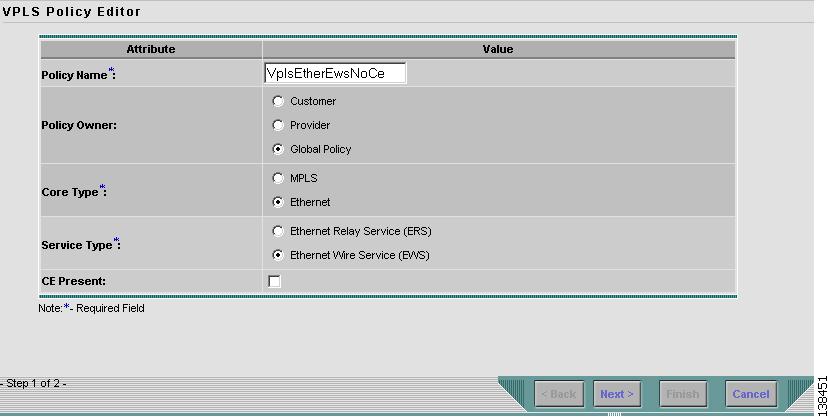
This section describes defining a VPLS policy with an Ethernet core type and an EWS service type without a CE present. Figure 8-34 is an example of the first page of this policy.
Figure 8-34 Ethernet/EWS Policy without a CE
Perform the following steps.
Step 1
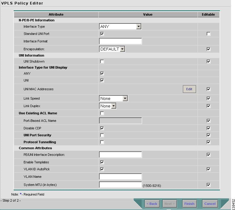
Click Next. The window in Figure 8-35 appears.
The Editable check box gives you the option of making a field editable. If you select the Editable check box, the service operator who is using this VPLS policy can modify the editable parameter during VPLS service request creation.
Figure 8-35 Ethernet/EWS without CE Policy Attributes
Step 2
Choose an Interface Type from the drop-down list.
You can choose to select a particular interface on a CE, N-PE, U-PE, or PE-AGG interface based on the service provider's POP design. The interfaces are:
•
ANY (Any interface can be chosen.)
•
Port-Channel (A bundle of ports that share the same characteristics—this gives the service provider the ability to aggregate bandwidth and protection.)
•
Ethernet
•
FastEthernet
•
GE-WAN
•
GigabitEthernet
•
TenGigabitEthernet
The value defined here functions as a filter to restrict the interface types an operator can see during VPLS service request creation. If defined as ANY, the operator can see all interface types.
Step 3
Select the Standard UNI Port check box to enable port security. This is the default. When you deselect the check box, the port is treated as an uplink with no security features, and the window dynamically changes to eliminate items related to port security.
Step 4
Enter an Interface Format as the slot number/port number for the CE interface (for example, 1/0 indicates that the interface is located at slot 1, port 0).
This is especially useful to specify here if you know that the link will always go through a particular interface's slot/port location on all or most of the network devices in the service.
Step 5
Choose a CE Encapsulation type. The choices are:
•
DOT1Q
•
DEFAULT
Step 6
Select the UNI Shutdown check box if you want to leave the UNI port shut during service activation, for example, when the service provider wants to deploy a service in the network but wants to activate it at a later time.
Step 7
Select the ANY check box to display all interface types as choices for the UNI interface (when creating service requests based on this policy). This check box is checked by default.
Step 8
Select the UNI check box to display all interfaces defined as type UNI as choices for the UNI interface (when creating service requests based on this policy). This check box is checked by default.
Step 9
Enter a Link Speed of none, 10, 100, 1000, or auto.
Step 10
Enter a Line Duplex of none, full, half, or auto.
Step 11
Select the Use Existing ACL Name check box if you want assign your own named access list to the port. By default, this check box is not selected and ISC automatically assigns a MAC-based ACL on the customer facing UNI port, based on values you enter in UNI MAC addresses (below).
Step 12
Enter a Port-Based ACL Name (if you selected the Use Existing ACL Name check box, as mentioned in the previous step).
Step 13
Enter one or more Ethernet MAC addresses in UNI MAC addresses. This selection is present only if you deselect the Use Existing ACL Name check box. Click the Edit button to bring up a pop-up window in which you enter MAC addresses to be allowed or denied on the port. You can also specify a range of addresses by setting a base MAC address and a filtered MAC address.
Step 14
Select the Disable CDP check box if you want to disable the Cisco Discover Protocol (CDP) on the UNI port.
Step 15
Select the UNI Port Security check box (see Figure 8-36) if you to want to provision port security-related CLIs to the UNI port by controlling the MAC addresses that are allowed to go through the interface.
a.
For Maximum Number of MAC address, enter the number of MAC addresses allowed for port security.
b.
For Aging, enter the length of time the MAC address can stay on the port security table.
c.
For Violation Action, choose what action will occur when a port security violation is detected:
•
PROTECT—Drops packets with unknown source addresses until a sufficient number of secure MAC addresses are removed to drop below the maximum value.
•
RESTRICT—Drops packets with unknown source addresses until a sufficient number of secure MAC addresses are removed to drop below the maximum value and causes the Security Violation counter to increment.
•
SHUTDOWN—Puts the interface into the error-disabled state immediately and sends an SNMP trap notification.
d.
In the Secure MAC Addresses field, enter one or more Ethernet MAC addresses.
Figure 8-36 UNI Port Security
Step 16
Select the Enable Storm Control check box (see Figure 8-37) to help prevent the UNI port from being disrupted by a broadcast, multicast or unicast storm. Enter a threshold value for each type of traffic. The value, which can be specified to two significant digits, represents the percentage of the total available bandwidth of the port. If the threshold of a traffic type is reached, further traffic of that type is suppressed until the incoming traffic falls below the threshold level.
Figure 8-37 Enable Storm Control
Step 17
Select the Protocol Tunnelling check box (see Figure 8-38) if you want to define the Layer 2 Bridge Protocol Data Unit (BPDU) frames that can be tunneled over the core to the other end.
Figure 8-38 Protocol Tunnelling
For each protocol that you check, enter the shutdown threshold and drop threshold for that protocol:
a.
Tunnel CDP—Enable Layer 2 tunnelling on Cisco Discover Protocol (CDP).
b.
CDP Threshold—Enter the number of packets per second to be received before the interface is shut down.
c.
cdp drop threshold—Enter the number of packets per second to be received at which point the interface will start dropping CDP packets.
d.
Tunnel VTP—Enable Layer 2 tunnelling on VLAN Trunk Protocol (VTP).
e.
VTP threshold—Enter the number of packets per second to be received before the interface is shut down.
f.
vtp drop threshold—Enter the number of packets per second to be received at which point the interface will start dropping VTP packets.
g.
Tunnel STP—Enable Layer 2 tunnelling on Spanning Tree Protocol (STP).
h.
STP Threshold—Enter the number of packets per second to be received before the interface is shut down.
i.
stp drop threshold—Enter the number of packets per second to be received at which point the interface will start dropping STP packets.
j.
Recovery Interval—Enter the amount of time, in seconds, to wait before recovering a UNI port.
Step 18
In the PE/UNI Interface Description field, enter an optional description, for example Customer-B EWS Service.
Step 19
Select the Enable Templates check box if you want to download free-format CLIs to a device. If you enable templates, you can create templates and data files to push down to the routers commands that are not normally supported by ISC. See Cisco IP Solution Center Infrastructure Reference, 4.1 for more information about template management.
Step 20
Select the VLANID AutoPick check box if you want ISC to choose a VLAN ID. If you do not select this check box, you will be prompted to provide the VLAN in a Provider VLAN ID field during service activation.
Step 21
Enter a VLAN NAME (optional) to specify a name to describe the VLAN. The name must be one token (no spaces allowed.) The limit for the VLAN name is 32 characters. The name has to be unique. Two VLANs cannot share the same name.
Step 22
Enter the System MTU in bytes.
Step 23
Enter the MTU Size in bytes.
The maximum transmission unit (MTU) size is configurable and optional. The default size is 9216, and the range is 1500 to 9216. ISC does not perform an integrity check for this customized value. If a service request goes to the Failed Deploy state because this size is not accepted, you must adjust the size until the Service Request is deployed.
In ISC 4.1, different platforms support different ranges.
•
For the 3750 and 3550 platforms, the MTU range is 1500-1546.
•
For the 7600 ethernet port, the MTU size is always 9216. Even with the same platform and same IOS release, different line cards support the MTU differently. For example, older line cards only take an MTU size of 9216 and newer cards support 1500-9216. However, ISC 4.1 uses 9216 in both cases.
•
For the 7600 SVI (interface VLAN), the MTU size is 1500-9216.
Step 24
Click Finish.
Note
The VC ID is mapped from the VPN ID. By default, ISC will "auto pick" this value. However, you can set this manually, if desired. This is done by editing the associated VPN configuration. The Edit VPN window has an Enable VPLS check box. When you check this box, you can manually enter a VPN ID in a field provided. For more information on creating and modifying VPNs, see Cisco IP Solution Center Infrastructure Reference, 4.1.

 Feedback