-
Cisco IP Solution Center L2VPN User Guide, 4.1
-
Index
-
About This Guide
-
Getting Started with L2VPN
-
ISC L2VPN and VPLS Concepts
-
Setting Up the ISC Service
-
Creating an L2VPN Policy
-
Managing an L2VPN Service Request
-
Creating an L2TPv3 Policy
-
Managing an L2TPv3 Service Request
-
Creating a VPLS Policy
-
Managing a VPLS Service Request
-
Using Autodiscovery for L2 Services
-
Generating L2 and VPLS Reports
-
Deploying, Monitoring and Auditing Service Requests
-
Setting Up VLAN Translation
-
 Feedback
Table Of Contents
Any Transport over MPLS (AToM)
Point-to-Point Ethernet (EWS and ERS)
Frame Relay over MPLS (FRoMPLS)
Layer 2 Tunnel Protocol Version 3 (L2TPv3)
Multipoint EWS for an MPLS-Based Provider Core
Multipoint ERS for an MPLS-Based Provider Core
VPLS for an Ethernet-Based (L2) Provider Core
Multipoint EWS for an Ethernet-Based Provider Core
Multipoint ERS for an Ethernet-Based Provider Core
Topology for Ethernet-Based VPLS
ISC L2VPN and VPLS Concepts
This chapter provides an overview of ISC L2VPN and VPLS service provisioning. It contains the following sections.
Overview
Layer 2 service provisioning for the IP Solution Center (ISC) 4.0 consists of the Layer 2 Virtual Private Network (L2VPN) Service and the Virtual Private LAN Service (VPLS).
L2VPN Services
L2VPN services are point-to-point. They provide Layer 2 point-to-point connectivity over either an MPLS or a pure IP (L2TPv3) core. These implementations, in turn, support service types, as follows:
•
L2VPN over MPLS core:
–
–
–
–
•
–
–
VPLS Services
VPLS services are multipoint. They provide multipoint connectivity over an MPLS or an Ethernet core. These implementations, in turn, support service types, as follows:
•
–
–
•
–
–
The remaining sections of this chapter provide an overview of these services. Instructions on creating policies and service requests for these services are provided in subsequent chapters of the manual.
L2VPN Service Provisioning
This section provides and overview of ISC provisioning for L2VPN over both MPLS and IP (L2TPv3) infrastructures. It contain the following sections:
•
•
Any Transport over MPLS (AToM)
Cisco's Any Transport over MPLS (AToM) enables service providers to deliver profitable, comprehensive services to their customers. The L2VPN service provisioning available in ISC is in the following areas:
•
•
Point-to-Point Ethernet (EWS and ERS)
The EWS and ERS services are delivered with the Cisco Metro Ethernet offering. The same network architecture can simultaneously provide both ERS and EWS connections to diverse customers. Additionally, this Metro Ethernet infrastructure can be used for access to higher-level services, such as IP-based virtual private networking, public internet communications, Voice over IP, or a combination of all applications.
Ethernet Wire Service (EWS)
An Ethernet Virtual Circuit (EVC) connects two physical User-to-Network Interfaces (UNI) such that the connection appears like a virtual private line to the customer. VLAN transparency and control protocol tunnelling are supplied by the implementation of 802.1Q-in-Q tag-stacking technology. Packets received on one UNI are transported directly to the other corresponding UNI.
Ethernet Relay Service (ERS)
An Ethernet Virtual Circuit (EVC) is used to logically connect endpoints, but multiple EVCs could exist per single UNI. Each EVC is distinguished by 802.1q VLAN tag identification. The ERS network acts as if the Ethernet frames have crossed a switched network, and certain control traffic is not carried between ends of the EVC. ERS is analogous to Frame Relay where the CE-VLAN tag plays the role of a Data-Link Connection Identifier (DLCI).
Topology for L2VPN Ethernet Over MPLS (ERS and EWS)
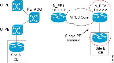
Ethernet Over MPLS (EoMPLS) is a tunnelling mechanism that allows the service provider to tunnel customer Layer 2 traffic though a Layer 3 MPLS network. It is important to remember that EoMPLS is a point-to-point solution only.
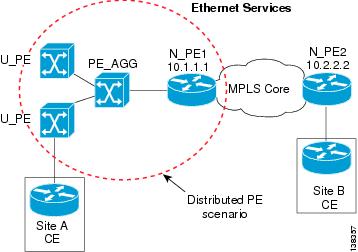
The following figures provide a reference for how EoMPLS is utilized. Ethernet Services can be distributed to the end customer in two ways.
•
Figure 2-1 Single PE scenario
•
Figure 2-2 Distributed PE Scenario
In both cases, a VLAN is assigned in one of the following ways:
•
•
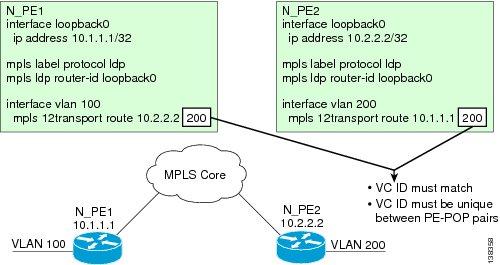
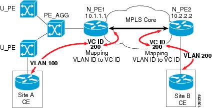
In EoMPLS, ISC creates a point-to-point tunnel and then targets the EoMPLS tunnel to the peer N-PE router through which the remote site can be reached. The remote N-PE is identified by its loopback address (in Figure 2-3, N-PE1 and N-PE2 have 10.1.1.1 and 10.2.2.2 as loopback addresses). In Figure 2-3, Site A has been allocated a VLAN-100 and Site B a VLAN-200. You can have different VLAN IDs at either end of the circuit because the VLANs have local significance only (that is, within the Ethernet access domain which is delimited by the N-PE).
For the N-PE that is serving Site A, a VLAN interface (Layer 3 interface) is created to terminate all L2 traffic for the customer, and an EoMPLS tunnel is configured on this interface. 1
Figure 2-3 Ethernet over MPLS Configuration
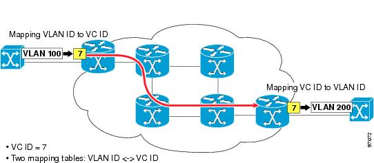
The VC ID that defines the EoMPLS tunnel is 200 as shown in Figure 2-3. Note that the VC ID has to be the same on both ends of the EoMPLS tunnel. On each N-PE, there is mapping done between the VLANs to the EoMPLS tunnel (Figure 2-4). For the overall connection, this mapping is: VLAN ID <-> VC ID <-> VLAN ID.
Figure 2-4 EoMPLS Tunnel
This VLAN-VC ID mapping lets the service provider reuse VLAN IDs in Access Domains (see Figure 2-5). The VLAN IDs allocated and used at each access domain do not have to be the same.
Figure 2-5 VLAN-VC ID Mapping
ATM over MPLS (ATMoMPLS)
With Cisco ATM over MPLS (ATMoMPLS), Cisco supports ATM Adaptation Layer 5 (AAL5) transport and Cell Relay over MPLS.
AAL5
AAL5 allows you to transport AAL5 PDUs from various customers over an MPLS backbone. ATM AAL5 extends the usability of the MPLS backbone by enabling it to offer Layer 2 services in addition to already existing Layer 3 services. You can enable the MPLS backbone network to accept AAL5 PDUs by configuring the provider edge (PE) routers at both ends of the MPLS backbone.
To transport AAL5 PDUs over MPLS, a virtual circuit is set up from the ingress PE router to the egress PE router. This virtual circuit transports the AAL5 PDUs from one PE router to the other. Each AAL5 PDU is transported as a single packet.
Cell Relay over MPLS
Cell Relay over MPLS allows you to transport ATM cells from various customers over an MPLS backbone. ATM Cell Relay extends the usability of the MPLS backbone by enabling it to offer Layer 2 services in addition to already existing Layer 3 services. You can enable the MPLS backbone network to accept ATM cells by configuring the provider edge (PE) routers at both ends of the MPLS backbone.
To transport ATM cells over MPLS, a virtual circuit is set up from the ingress PE router to the egress PE router. This virtual circuit transports the ATM cells from one PE router to the other. Each MPLS packet can contain one or more ATM cells. The encapsulation type is AAL0.
Topology for ATMoMPLS
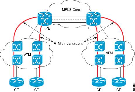
Only the single PE scenario is supported as shown in Figure 2-6.
Figure 2-6 Configuring AAL5 and Cell Relay over MPLS
Frame Relay over MPLS (FRoMPLS)
With Cisco AToM for Frame Relay, customer Frame Relay traffic can be encapsulated in MPLS packets and forwarded to destinations required by the customer. Cisco AToM allows service providers to quickly add new sites with less effort than typical Frame Relay provisioning.
Frame Relay over MPLS enables a service provider to transport Frame Relay frames across an MPLS backbone. This extends the reachability of Frame Relay and allows service providers to aggregate frame transport across a common packet backbone. The service provider can integrate an existing Frame Relay environment with the packet backbone to improve operational efficiency and to implement the high-speed packet interfaces to scale the Frame Relay implementations.
Transporting Frame Relay frames across MPLS networks provides a number of benefits, including:
•
•
•
Topology for FRoMPLS
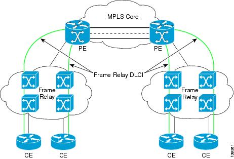
Only the single PE scenario is supported as shown in Figure 2-7.
Figure 2-7 Frame Relay over MPLS
Layer 2 Tunnel Protocol Version 3 (L2TPv3)
IP-based Layer 2 Tunnel Protocol Version 3 (L2TPv3) provides Layer 2 point-to-point connectivity over a pure IP (non-MPLS) infrastructure. L2TPv3 concepts are covered in the following sections:
Overview of L2TPv3
L2TPv3 allows a service provider to replace a legacy switch-based core with an IP router-based core without any impact to a customer's existing Layer 2 connectivity.
L2TPv3 uses a directed Control Channel session between edge routers for creating and maintaining connections. Forwarding occurs through the use of IP packet forwarding between two edge devices. An IP header and the L2TPv3 header are used to forward packets between routers. The external header is an IP header that routes tunneled packets over the IP backbone to the egress Provider Edge (PE) device. The L2TPv3 header determines the egress interface, and binds the Layer 2 egress interface to the tunnel.
L2TPv3 defines the L2TP protocol for tunnelling Layer 2 payloads over an IP core network using Layer 2 virtual private networks (VPNs). Benefits of this feature include the following:
•
•
•
•
•
•
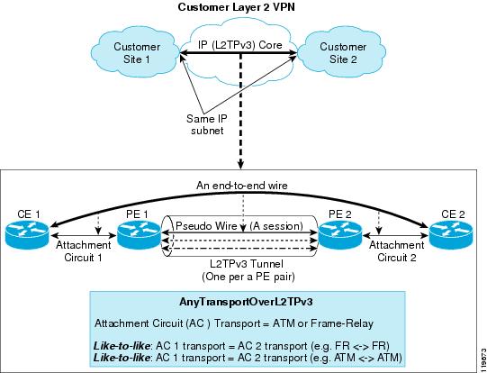
Figure 2-8 shows an example of how the L2TPv3 feature is used for setting up VPNs using Layer 2 tunnelling over an IP network. All traffic between two customer network sites is encapsulated in IP packets carrying L2TP data messages and sent across an IP network. The backbone routers of the IP network treat the traffic as any other IP traffic and need not know anything about the customer networks.
Figure 2-8 L2TPv3 Operation
L2TPv3 Session Parameters
L2TPv3 sessions can be setup in either dynamic mode or static mode.
Static L2TPv3 Sessions
Typically, the L2TP control plane is responsible for negotiating session parameters, such as the session ID or the cookie, in order to set up the session. However, some IP networks require sessions to be configured so that no signaling is required for session establishment. You can, therefore, set up static L2TPv3 sessions for a PE router by configuring fixed values for the fields in the L2TP data header. A static L2TPv3 session allows the PE to tunnel Layer 2 traffic as soon as the attachment circuit to which the session is bound comes up.
Dynamic L2TPv3 Sessions
A dynamic L2TP session is established through the exchange of control messages containing attribute-value pairs (AVPs). Each AVP contains information about the nature of the Layer 2 link being forwarded, including the payload type, virtual circuit (VC) ID, and so on.
Multiple L2TP sessions (one for each forwarded Layer 2 circuit) can exist between a pair of PEs, and can be maintained by a single control channel. Session IDs and cookies are dynamically generated and exchanged as part of a dynamic session setup. Information such as sequencing configuration is also exchanged.
Sequencing
Although the correct sequence of received Layer 2 frames is guaranteed by some Layer 2 technologies (by the nature of the link, such as a serial line) or the protocol itself, forwarded Layer 2 frames can be lost, duplicated, or reordered when they traverse a network as IP packets. If the Layer 2 protocol does not provide an explicit sequencing mechanism, ISC lets you configure L2TPv3 to sequence its data packets.
Session Cookie
The L2TPv3 header contains a control channel cookie field that has a variable length of 0, 4, or 8 bytes according to the cookie length supported by a given platform for packet decapsulation. The control channel cookie length can be manually configured or auto-picked by ISC for static sessions, or dynamically determined for dynamic sessions.
The variable cookie length does not present a problem when the same platform is at both ends of an L2TPv3 control channel. However, when different platforms interoperate across an L2TPv3 control channel, both platforms must encapsulate packets with a 4-byte cookie length.
Frame Relay Transport
In L2TPv3 frame relay, traffic is encapsulated in IP/L2TPv3 packets and forwarded across the IP network. When encapsulating Frame Relay over IP, the Frame Relay header is passed in the payload of the packet. Thus the bits for Backward Explicit Congestion Notification (BECN), Forward Explicit Congestion Notification (FECN), Discard Eligibility (DE) and Command/Response (C/R) ar carried across the IP network.
•
•
ISC supports the Multilink Frame Relay (MFR) interface. It is a bundle interface that combines several frame relay interfaces into one super interface.
From a provisioning point of view, you only configure the MFR interface but do not create it. You precreate the bundle (MFR) and the bundle-links (the Frame Relay interfaces that make up the MFR interface).
ATM Transport
L2TPv3 supports two modes of ATM transport between two PEs: Virtual Path (VP) and Virtual Circuit (VC). In VP mode, cells coming into a predefined PVP on the ATM interface to be transported over an L2TPv3 pseudowire to a predefined PVP on the egress ATM interface. This task binds a PVP to an L2TPv3 pseudowire for Xconnect service. In VC mode, L2TPv3 can be used to carry any type of AAL traffic over the pseudowire. It will not distinguish OAM cells from user data cells. In this mode, PM and Security OAM cells are also transported over the pseudowire.
The encapsulations of an ATM cell can be either AAL5 or cell relay (AAL0). In cell relay mode, the ATM interface receives cells and transports them across the IP core. Cell relay with cell packing is used to send multiple cells in one IP frame, which improves the efficiency of cell transport. The signaling is transparently passed through the IP cloud, rather than being terminated at the PE.
VPLS Service Provisioning
VPLS is a multipoint Layer 2 VPN that connects two or more customer devices using EoMPLS bridging techniques. VPLS EoMPLS is an MPLS-based provider core, that is, the PE routers have to cooperate to forward customer Ethernet traffic for a given VPLS instance in the core.
A VPLS essentially emulates an Ethernet switch from a user's perspective. All connections are peers within the VPLS and have direct communications. The architecture is actually that of a distributed switch.
Multiple attachment circuits have to be joined together by the provider core. The provider core has to simulate a virtual bridge that connects these multiple attachment circuits together. To achieve this, all PE routers participating in a VPLS instance form emulated VCs among them.
A Virtual Forwarding Instance (VFI) is created on the PE router for each VPLS instance. PE routers make packet-forwarding decisions by looking up the VFI of a particular VPLS instance. The VFI acts like a virtual bridge for a given VPLS instance. More than one attachment circuit belonging to a given VPLS can be connected to this VFI. The PE router establishes emulated VCs to all the other PE routers in that VPLS instance and attaches these emulated VCs to the VFI. Packet forwarding decisions are based on the data structures maintained in the VFI. All the PE routers in the VPLS domain use the same VC-ID for establishing the emulated VCs. This VC-ID is also called the VPN-ID in the context of the VPLS VPN. For more information, see the following sections:
•
•
Multipoint EWS for an MPLS-Based Provider Core
With multipoint EWS, the PE router forwards all Ethernet packets received from an attachment circuit, including tagged, untagged, and Bridge Protocol Data Unit (BPDU) to either:
•
•
Multipoint ERS for an MPLS-Based Provider Core
With multipoint ERS, the PE router forwards all Ethernet packets with a particular VLAN tag received from an attachment circuit, excluding BPDU, to another attachment circuit or an emulated VC if the destination MAC address is found in the L2 forwarding table (VFI). If the destination MAC address is not found or if it is a broadcast/multicast packet, then it is sent on all other attachment circuits and emulated VCs belonging to the VPLS instance. The demultiplexing VLAN tag used to identify a VPLS domain is removed prior to forwarding the packet to the outgoing Ethernet interfaces or emulated VCs because it only has local significance.
Topology for MPLS-Based VPLS
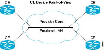
From a customer point of view there is no topology for VPLS. All the CE devices are connected to a logical bridge emulated by the provider core. Therefore, the CE devices see a single emulated LAN as shown in Figure 2-9.
Figure 2-9 MPLS-Based VPLS Topology
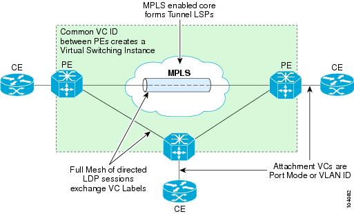
The PE routers must create a full-mesh of emulated virtual circuits (VCs) to simulate the emulated LAN seen by the CE devices. Forming a full-mesh of emulated VCs simplifies the task of emulating a LAN in the provider core. One property of a LAN is to maintain a single broadcast domain. That is, if a broadcast, multicast, or unknown unicast packet is received on one of the attachment circuits, it has to be sent to all other CE devices participating in that VPLS instance. The PE device handles this case by sending such a packet on all other attachment circuits and all the emulated circuits originating from that PE. With a full-mesh of emulated VCs, such a packet will reach all other PE devices in that VPLS instance. See Figure 2-10.
Figure 2-10 Full Mesh of Emulated VCs
VPLS for an Ethernet-Based (L2) Provider Core
With an Ethernet-based provider core, customer traffic forwarding is trivial in the core. VPLS for an Ethernet-based provider core is a multipoint Layer 2 VPN that connects two or more customer devices using 802.1Q-in-Q tag-stacking technology. A VPLS essentially emulates an Ethernet switch from a users perspective. All connections are peers within the VPLS and have direct communications. The architecture is actually that of a distributed switch.
For more information on VPLS for an Ethernet-based provided core, see the following sections:
•
•
•
Multipoint EWS for an Ethernet-Based Provider Core
Multipoint EWS is a service that emulates a point-to-point Ethernet segment. The EWS service encapsulates all frames that are received on a particular User to Network Interface (UNI) and transports these frames to a single egress UNI without reference to the contents contained within the frame. This service operation means that EWS can be used for untagged or VLAN tagged frames and that the service is transparent to all frames offered. Because the EWS service is unaware that VLAN tags might be present within the customer frames, the service employs a concept of "All to One" bundling.
Multipoint ERS for an Ethernet-Based Provider Core
Multipoint ERS models the connectivity offered by existing Frame Relay networks by using VLAN indices to identify virtual circuits between sites. ERS does, however, offer a far greater degree of QoS functionality depending upon the service provider's implementation and the customer's acceptance of VLAN indices that are administratively controlled by the service provider. Additionally, ERS service multiplexing capability offers lower cost of ownership for the enterprise as a single interface can support many virtual interfaces.
Topology for Ethernet-Based VPLS
Ethernet-based VPLS differs from the point-to-point L2VPN definitions of EWS and ERS by providing a multipoint connectivity model. The VPLS service does not map an interface or VLAN to a specific point-to-point pseudo-wire, but instead it models the operation of a virtual Ethernet switch. VPLS uses the customer's MAC address to forward frames to the correct egress UNI within the service provider's network for the EWS.
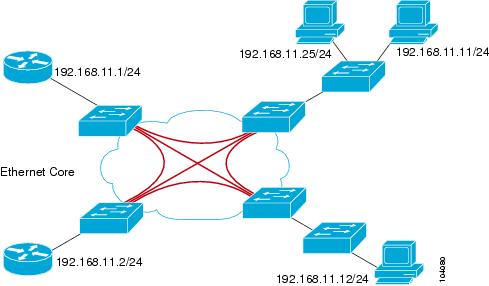
The EWS service emulates the service attributes of an Ethernet switch and learns source MAC to interface associations, flooding unknown broadcast and multicast frames. Figure 2-11 illustrates an EWS VPLS topology.
Figure 2-11 VPLS EWS Topology
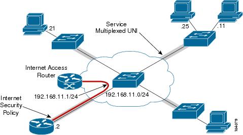
The Ethernet Relay Service (ERS) offers the any-to-any connectivity characteristics of EWS and the service multiplexing. This combination enables a single UNI to support a customer's intranet connection and one or more additional EVCs for connection to outside networks, ISPs, or content providers. Figure 2-12 illustrates an ERS VPLS multipoint topology.
Figure 2-12 VPLS ERS Multipoint Topology
1 This configuration is based on the Cisco 7600 Optical Services Router. Other routers, such as the Cisco 7200, have different configurations.