-
Cisco IP Solution Center L2VPN User Guide, 4.1
-
Index
-
About This Guide
-
Getting Started with L2VPN
-
ISC L2VPN and VPLS Concepts
-
Setting Up the ISC Service
-
Creating an L2VPN Policy
-
Managing an L2VPN Service Request
-
Creating an L2TPv3 Policy
-
Managing an L2TPv3 Service Request
-
Creating a VPLS Policy
-
Managing a VPLS Service Request
-
Using Autodiscovery for L2 Services
-
Generating L2 and VPLS Reports
-
Deploying, Monitoring and Auditing Service Requests
-
Setting Up VLAN Translation
-
 Feedback
Table Of Contents
Performing Device Settings to Support ISC
Configuring Switches in VTP Transparent Mode
Setting the Loopback Addresses on N-PE Devices
Creating Target Devices and Assign Roles (N-PE or U-PE)
Setting the L2TPv3 Local Switching Loopback
Defining a Service Provider and Its Regions
Defining Customers and Their Sites
Creating Named Physical Circuits
Creating NPCs Through an NPC GUI Editor
Creating NPC Links Through the Autodiscovery Process
Setting Up the ISC Service
You define the service-related elements, such as target devices, VPNs, and network links. Normally, you create these elements once. This chapter contains the basic steps to set up the Cisco IP Solution Center (ISC) service for an L2VPN, L2TPv3, or VPLS service. It contains the following sections:
•
Performing Device Settings to Support ISC
•
•
•
•
Note
Performing Device Settings to Support ISC
Two device settings must be configured to support the use of ISC in the network:
•
•
Note
Configuring Switches in VTP Transparent Mode
For security reasons, ISC requires VTPs to be configured in transparent mode on all the switches involved in ERS or EWS services before provisioning L2VPN service requests. To set the VTP mode, enter the following Cisco IOS commands:
Switch# configure terminalSwitch(config)# vtp mode transparentEnter the following Cisco IOS command to verify that the VTP mode has changed to transparent:
Switch# Show vtp statusSetting the Loopback Addresses on N-PE Devices
See the section "Setting the Loopback Address" section for information.
Creating Target Devices and Assign Roles (N-PE or U-PE)
Every network element that ISC manages must be defined as a device in the system. An element is any device from which ISC can collect information. In most cases, devices are Cisco IOS routers that function as N-PE, U-PE, and P.
For detailed steps to create devices, see Cisco IP Solution Center Infrastructure Reference, 4.1.
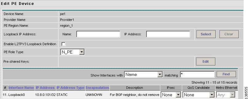
Setting the Loopback Address
The loopback address for the N-PE has to be properly configured for an AToMPLS connection. The IP address specified in the loopback interface must be reachable from the remote pairing PE. The LDP tunnels are established between the two loopback interfaces of the PE pair.
See Figure 3-1 for an example of a loopback address.
Figure 3-1 PE Loopback Address
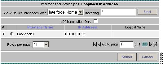
To prevent a wrong loopback address being entered into the system, the loopback IP address field on the GUI is read only. You choose the loopback address with the help of a separate pop-up window, which you access by clicking the Select button. This ensures that you will select only a valid loopback address defined on the device. See Figure 3-2.
Figure 3-2 Select Device Interface
This feature ensures that a valid loopback address is set.
To further narrow the search, you can select the LDPTermination Only check box and click the Select button. This will then limit the list to the LDP-terminating loopback interface(s).
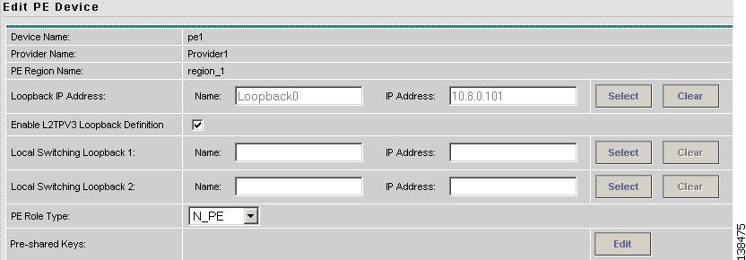
Setting the L2TPv3 Local Switching Loopback
Local switching requires that you select two loopback addresses. Each loopback must be unique. To set a second loopback address, select the Enable L2TPV3 Loopback Definition check box. See Figure 3-3.
Figure 3-3 PE Local Switching Loopback Addresses
This causes two additional GUI fields to appear, Local Switching Loopback 1 and Local Switching Loopback 2. Use the Select button to set the local switching loopbacks.
Defining a Service Provider and Its Regions
You must define the service provider administrative domain before provisioning L2VPN. The provider administrative domain is the administrative domain of an ISP with one BGP autonomous system (AS) number. The network owned by the provider administrative domain is called the backbone network. If an ISP has two AS numbers, you must define it as two provider administrative domains. Each provider administrative domain can own many region objects.
For detailed steps to define the provider administrative domain, see Cisco IP Solution Center Infrastructure Reference, 4.1.
Defining Customers and Their Sites
You must define customers and their sites before provisioning L2VPN. A customer is a requestor of a VPN service from an ISP. Each customer can own many customer sites. Each customer site belongs to one and only one Customer and can own many CPEs. For detailed steps to create customers, see Cisco IP Solution Center Infrastructure Reference, 4.1.
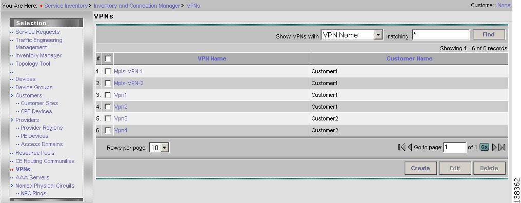
Defining VPNs
You must define VPNs before provisioning L2VPN or VPLS. In L2VPN, one VPN can be shared by different service types. In VPLS, one VPN is required for each VPLS instance.
To create a VPN, perform the following steps.
Step 1
Step 2
Figure 3-4 Defining a VPN
For detailed steps to create VPNs, see Cisco IP Solution Center Infrastructure Reference, 4.1.
Note
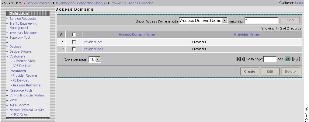
Creating Access Domains
For L2VPN and VPLS, you create an Access Domain if you provision an Ethernet-based service and want ISC to automatically assign a VLAN for the link from the VLAN pool.
Note
For each Layer 2 access domain, you need a corresponding Access Domain object in ISC. During creation, you select all the N-PE devices that are associated with this domain. Later, one VLAN pool can be created for an Access Domain. This is how N-PEs are automatically assigned a VLAN. See Figure 3-5.
Before you begin, be sure that you:
•
•
•
•
•
•
To create an Access Domain, perform the following steps.
Step 1
Step 2
Figure 3-5 Create an Access Domain
The Access Domains window contains the following:
•
•
•
–
–
–
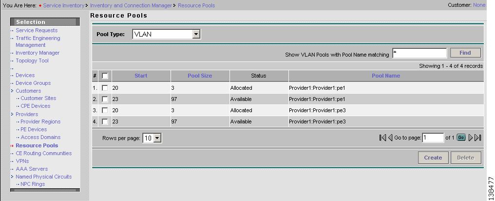
Creating VLAN Pools
For L2VPN and VPLS, you create a VLAN pool so that ISC can assign a VLAN to the links. VLAN ID pools are defined with a starting value and a size of the VLAN pool. A VLAN pool can be attached to an access domain. During the deployment of an Ethernet service, VLAN IDs can be auto-allocated from the access domain's pre-existing VLAN pools. When you deploy a new service, ISC changes the status of the VLAN pool from Available to Allocated. Auto-allocation gives the service provider tighter control of VLAN ID allocation.
You can also allocate VLAN IDs manually.
Note
Note
Create one VLAN pool per access domain. Within that VLAN pool, you can define multiple ranges.
Before you begin, be sure that you:
•
•
•
•
Perform these steps if you want to have ISC automatically assign a VLAN to the links.
Step 1
Step 2
Step 3
Step 4
Figure 3-6 VLAN Resource Pools
Step 5
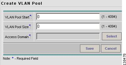
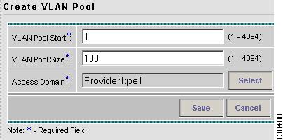
Figure 3-7 Create VLAN Pool
Step 6
Step 7
Step 8
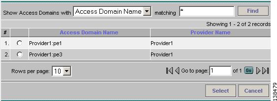
The Access Domain for New VLAN Pool dialog box appears as shown in Figure 3-8.
If the correct access domain is showing, continue with Step 9.
Figure 3-8 Access Domain for New VLAN Pool
a.
b.
Figure 3-9 Updated Create VLAN Pool
Step 9
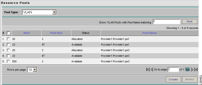
The updated VLAN Resource Pools window appears as shown in Figure 3-10.
Note
Note
Figure 3-10 Updated VLAN Resource Pools
Step 10
Creating a VC ID Pool
VC ID pools are defined with a starting value and a size of the VC ID pool. A given VC ID pool is not attached to any inventory object (a provider or customer). During deployment of an L2VPN or VPLS service, the VC ID can be auto-allocated from the same VC ID pool or you can set it manually.
Note
Create one VC ID pool per network.
In a VPLS instance, all N-PE routers use the same VC ID for establishing emulated Virtual Circuits (VCs). The VC-ID is also called the VPN ID in the context of the VPLS VPN. (Multiple attachment circuits must be joined by the provider core in a VPLS instance. The provider core must simulate a virtual bridge that connects the multiple attachment circuits. To simulate this virtual bridge, all N-PE routers participating in a VPLS instance form emulated VCs among them.)
Note
Before you begin, be sure that you have the following information for each VC ID pool you must create:
•
•
Perform these steps for all L2VPN and VPLS services.
Step 1
Step 2
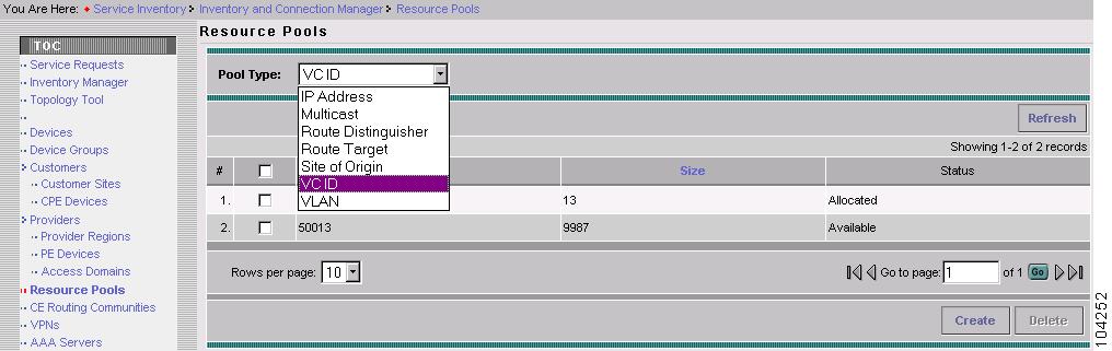
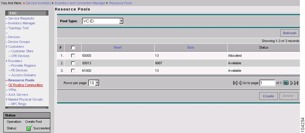
Select Resource Pools. The Resource Pools window appears.
Step 3
Figure 3-11 VC ID Resource Pools
Step 4
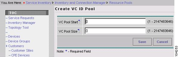
Figure 3-12 Create VC ID Pool
Step 5
Step 6
Step 7
Figure 3-13 Updated VC ID Resource Pools
Creating Named Physical Circuits
Before creating an L2VPN, L2TPv3, or VPLS service request, you must predefine the physical links between CEs and PEs. The Named Physical Circuit (NPC) represents a link going through a group of physical ports. Thus, more than one logical link can be provisioned on the same NPC; therefore, the NPC is defined once but used during several L2VPN or VPLS service request creations.
There are two ways to create the NPC links:
•
•
An NPC definition must observe the following creation rules:
•
•
If you are inserting NPC information for a link between a CE and UNI, you enter the information as:
•
•
•
•
If you are inserting NPC information for a CE not present case, you enter the information as:
•
•
•
•
If you have a single N-PE and no CE (no U-PE and no CE), you do not have to create an NPC since there is no physical link that needs to be presented.
If an NPC involves two or more links (three or more devices), for example, it connects ence11, enpe1, and enpe12, you can construct this NPC as follows:
•
•
•
Creating NPCs Through an NPC GUI Editor
Perform the following steps to create NPCs through the NPC GUI editor.
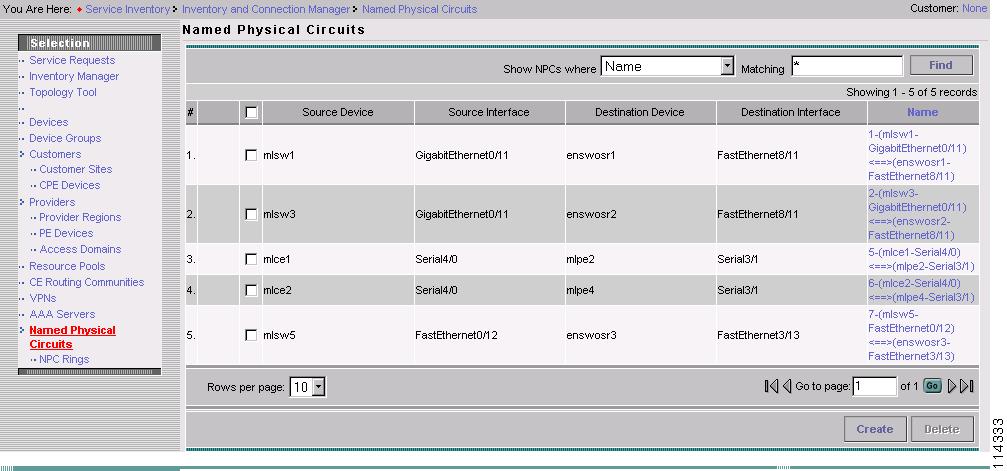
Step 1
Step 2
Step 3
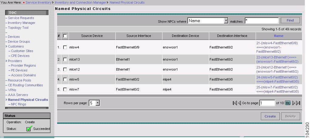
Figure 3-14 Named Physical Circuit
To create a new NPC, you choose a CE as the beginning of the link and a N-PE as the end. If more than two devices are in a link, you can add or insert more devices (or a ring) to the NPC. Note that the new device or ring added is always placed after the device selected, while a new device or ring inserted is placed before the device selected.
Each line on the Point-to-Point Editor represents a physical link. Each physical link has five attributes:
•
•
•
•
•
Note
Source Device is the beginning of the link and Destination Device is the end of the link.
In the following example, there is a link with one end connecting a device called mlce1 on interface Ethernet0/0 and another link connecting to mlpe4 on interface FastEthernet0/0. Use the following steps to enter these devices.
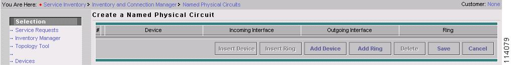
Step 4
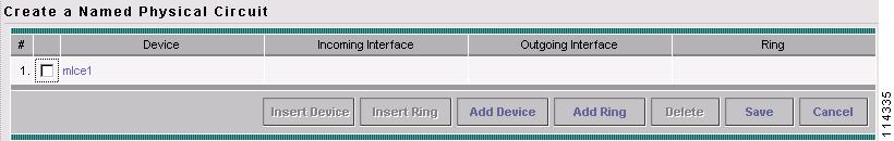
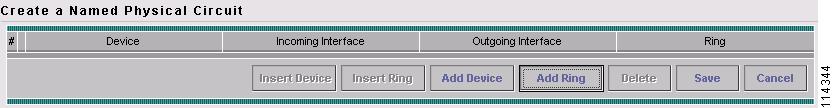
The Create a Named Physical Circuit window appears. See Figure 3-15.
Figure 3-15 Create a Named Physical Circuit
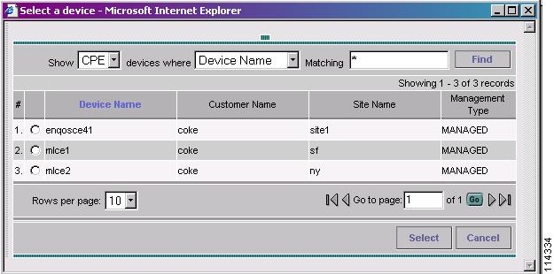
Step 5
Figure 3-16 Choose a CPE
Step 6
Step 7
Figure 3-17 Device Selected for NPC
Step 8
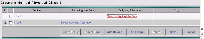
For this example, click Add Device to add the N-PE.
Step 9
Step 10
Figure 3-18 Second Device Selected for NPC
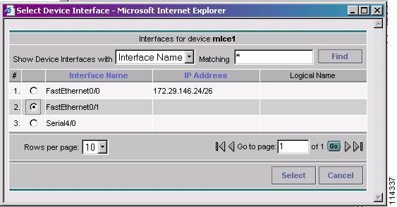
Step 11
A list of interfaces, similar to the one in Figure 3-19, that were entered into the system appears.
Figure 3-19 Select Outgoing Interface
Step 12
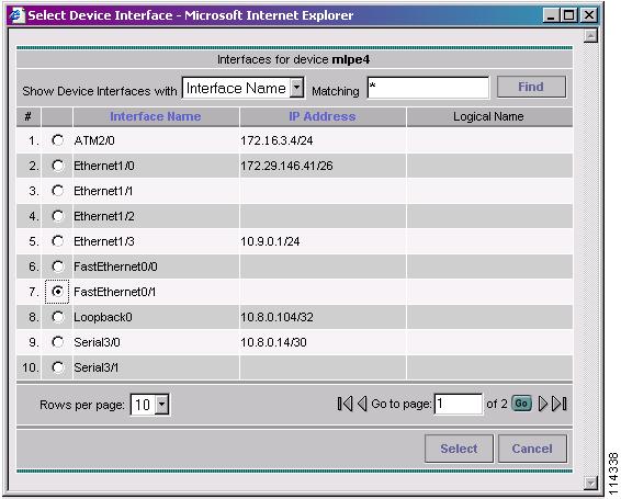
Step 13
A list of interfaces, similar to the one in Figure 3-20, that were entered into the system appears.
Figure 3-20 Select Incoming Interface
.
Step 14
If you did not create a ring that you want to insert into the NPC, go to Step 25.
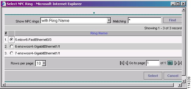
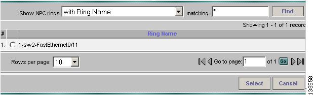
Step 15
Note
Figure 3-21 Select NPC Ring
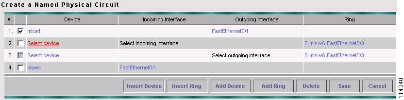
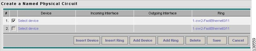
Step 16
Figure 3-22 Create a Named Physical Circuit
Step 17
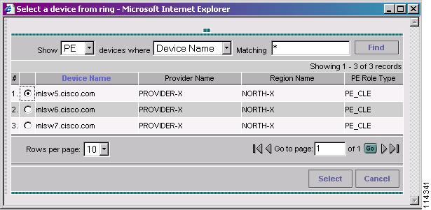
Step 18
Figure 3-23 Select a Device from the Ring
Step 19
Step 20
Step 21
Step 22
Step 23
Step 24
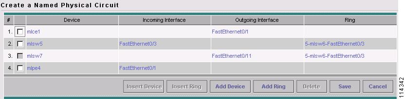
The NPC that includes the ring is now complete as shown in Figure 3-24.
Figure 3-24 Ring Complete
Step 25
Figure 3-25 Created NPC
Creating a Ring-Only NPC
You can also create an NPC that contains only a ring without specifying CE.
Step 1
Step 2
Step 3
Figure 3-26 Create an NPC that is a Ring
Step 4
Figure 3-27 Select a Ring
Step 5
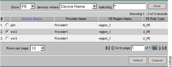
Figure 3-28 Select Device
Step 6
Figure 3-29 Select the Beginning of the Ring
Step 7
Step 8
Step 9
Note
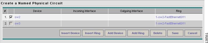
Step 10
Figure 3-30 Ring-Only NPC
Step 11
Creating NPC Links Through the Autodiscovery Process
With autodiscovery, the existing connectivity of network devices can be automatically retrieved and stored in the ISC database. NPCs are further abstracted from the discovered connectivity.
For detailed steps to create NPCs using autodiscovery, see Cisco IP Solution Center Infrastructure Reference, 4.1.