-
Cisco IP Solution Center L2VPN User Guide, 4.1
-
Index
-
About This Guide
-
Getting Started with L2VPN
-
ISC L2VPN and VPLS Concepts
-
Setting Up the ISC Service
-
Creating an L2VPN Policy
-
Managing an L2VPN Service Request
-
Creating an L2TPv3 Policy
-
Managing an L2TPv3 Service Request
-
Creating a VPLS Policy
-
Managing a VPLS Service Request
-
Using Autodiscovery for L2 Services
-
Generating L2 and VPLS Reports
-
Deploying, Monitoring and Auditing Service Requests
-
Setting Up VLAN Translation
-
 Feedback
Table Of Contents
Defining an Ethernet ERS Policy with a CE
Defining an Ethernet ERS Policy without a CE
Defining an Ethernet EWS Policy with a CE
Defining an Ethernet EWS Policy without a CE
Defining a Frame Relay Policy with a CE
Defining a Frame Relay Policy without a CE
Defining an ATM Policy with a CE
Defining an ATM Policy without a CE
Creating an L2VPN Policy
This chapter covers the basic steps to create an L2VPN policy. It contains the following sections:
•
Defining an Ethernet ERS Policy with a CE
•
•
•
•
•
•
•
Defining an L2VPN Policy
You must define an L2VPN policy before you can provision a Cisco IP Solution Center (ISC) service. An L2VPN policy defines the common characteristics shared by the end-to-end wire attributes and Attachment Circuit (AC) attributes.
Note
A policy can be shared by one or more service requests that have similar service requirements. The Editable check box gives the network operator the option of making a field editable. If the value is set to editable, the service request creator can change to other valid values for the particular policy item. If the value is not set to editable, the service request creator cannot change the policy item.
The four major categories of an L2VPN policy correspond to the four major services that L2VPN provides:
•
•
•
•
A policy is a template of most of the parameters needed to define an L2VPN service request. After you define it, an L2VPN policy can be used by all the L2VPN service requests that share a common set of characteristics.
You create a new L2VPN policy whenever you create a new type of service or a service with different parameters. L2VPN policy creation is normally performed by experienced network engineers.
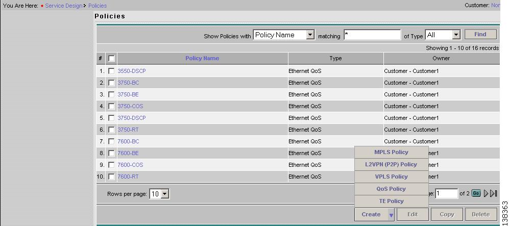
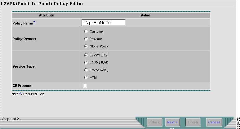
To define an L2VPN policy in ISC, use the following steps. See Figure 4-1.
Step 1
Step 2
Figure 4-1 Creating an L2VPN Policy
Step 3
Figure 4-2 Choosing a Policy Type
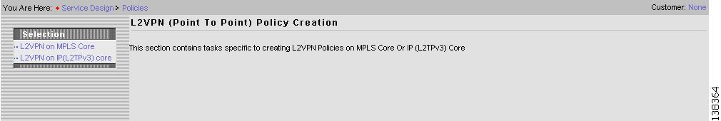
Step 4
Figure 4-3 Creating an L2VPN Policy
Step 5
Step 6
There are three types of L2VPN policy ownership:
•
•
•
This ownership has relevance when the ISC Role-Based Access Control (RBAC) comes into play. For example, an L2VPN policy that is customer-owned can only be seen by operators who are allowed to work on this customer-owned policy.
Similarly, operators who are allowed to work on a provider's network can view, use, and deploy a particular provider-owned policy.
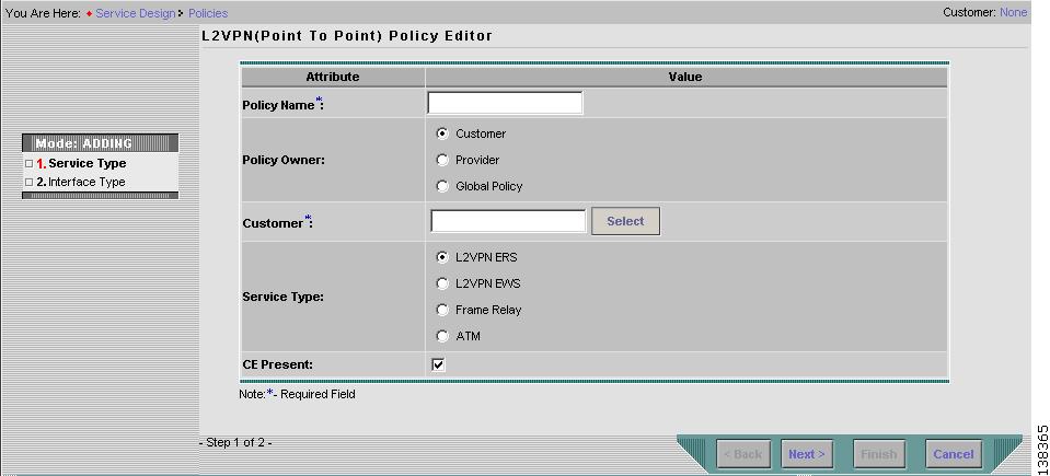
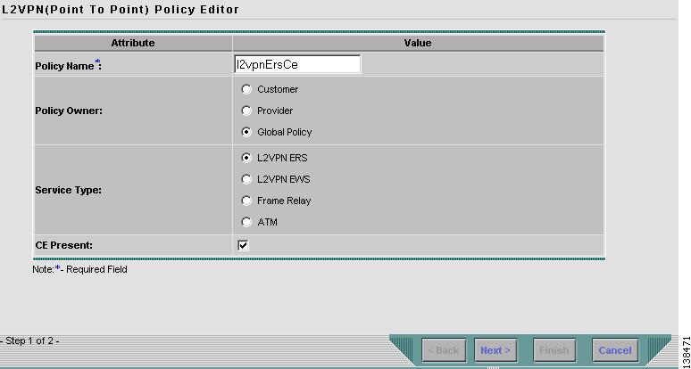
Step 7
Step 8
There are four service types for L2VPN policies:
•
•
•
•
Subsequent sections of this chapter cover setting up the policies for each of these services.
Step 9
If you do not select the CE Present check box, ISC asks the service operator, during service activation, only for the U-PE or the N-PE router and customer-facing interface.
Step 10
The next sections contain examples of setting policies for the service types, with and without a CE present.
Defining an Ethernet ERS Policy with a CE
This section describes defining an Ethernet ERS policy with CE present. Figure 4-4 is an example of the first page of this policy.
Figure 4-4 Ethernet ERS Policy with a CE
Step 1
The Editable check box gives you the option of making a field editable. If you select the Editable check box, the service operator who is using this L2VPN policy can modify the editable parameter during L2VPN service request creation.
Figure 4-5 Ethernet ERS with CE Policy Attributes
Step 2
Step 3
You can choose to select a particular interface on a U-PE, or N-PE interface based on the service provider's POP design. The interfaces are:
•
•
•
•
•
•
•
The value defined here functions as a filter to restrict the interface types an operator can see during L2VPN service request creation.
Step 4
This is especially useful to specify here if you know that the link will always go through a particular interface's slot/port location on all or most of the network devices in the service.
Step 5
•
•
If DEFAULT is the CE encapsulation type, ISC shows another field for the UNI port type.
Note
Step 6
Step 7
Step 8
Step 9
Step 10
Step 11
Step 12
Step 13
Step 14
Step 15
Step 16
Step 17
•
•
Note
Step 18
Step 19
a.
b.
c.
•
•
•
d.
Figure 4-6 UNI Port Security
Step 20
Figure 4-7 Enable Storm Control
Step 21
Step 22
•
•
•
Note
Step 23
Step 24
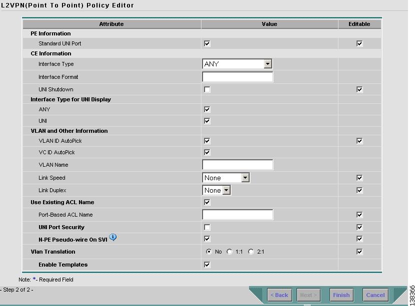
Defining an Ethernet ERS Policy without a CE
This section describes defining an Ethernet ERS policy with out a CE present. Figure 4-6 is an example of the first page of this policy.
Figure 4-8 Ethernet ERS Policy without a CE
Step 1
The Editable check box gives you the option of making a field editable. If you select the Editable check box, the service operator who is using this L2VPN policy can modify the editable parameter during L2VPN service request creation.
Figure 4-9 Ethernet ERS without CE Policy Attributes
Step 2
You can choose to select a particular interface as a CE, N-PE, or U-PE interface based on the service provider's POP design. The interfaces are:
•
•
•
•
•
•
•
The value defined here functions as a filter to restrict the interface types an operator can see during L2VPN service request creation.
Step 3
Step 4
This is especially useful to specify here if you know that the link will always go through a particular interface's slot/port location on all or most of the network devices in the service.
Step 5
•
•
If DEFAULT is the CE encapsulation type, ISC shows another field for the UNI port type.
Note
Step 6
Step 7
Step 8
Step 9
Step 10
Step 11
Step 12
Step 13
Step 14
Step 15
Step 16
Step 17
•
•
Note
Step 18
Step 19
a.
b.
c.
•
•
•
d.
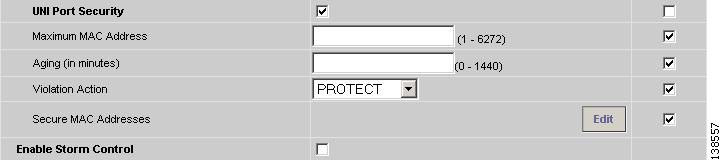
Figure 4-10 UNI Port Security
Step 20
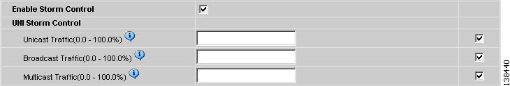
Figure 4-11 Enable Storm Control
Step 21
Step 22
•
•
•
Note
Step 23
Step 24
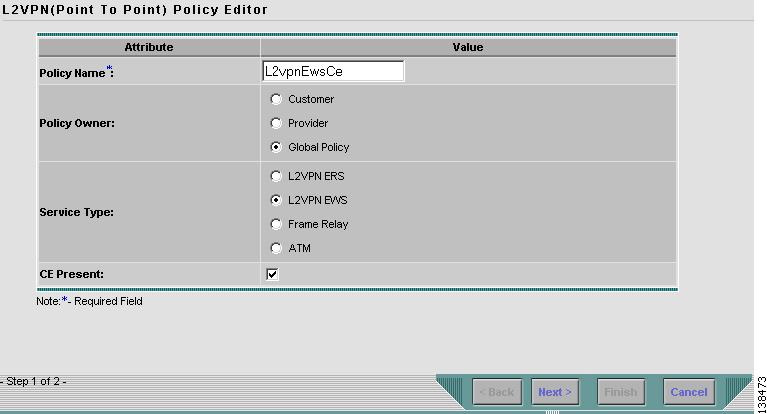
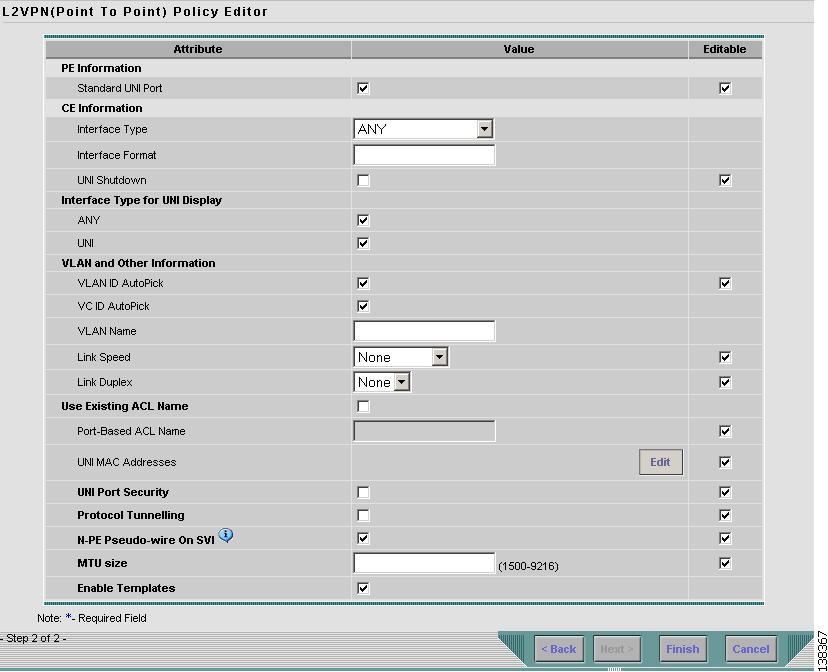
Defining an Ethernet EWS Policy with a CE
This section describes defining an Ethernet EWS policy with CE present. Figure 4-12 is an example of the first page of this policy.
Figure 4-12 Ethernet EWS Policy with a CE
Step 1
The Editable check box gives you the option of making a field editable. If you select the Editable check box, the service operator who is using this L2VPN policy can modify the editable parameter during L2VPN service request creation.
Figure 4-13 Ethernet EWS with CE Policy Attributes
Step 2
Step 3
You can choose to select a particular interface on a U-PE or N-PE interface based on the service provider's POP design. The interfaces are:
•
•
•
•
•
•
•
The value defined here functions as a filter to restrict the interface types an operator can see during L2VPN service request creation.
Step 4
This is especially useful to specify here if you know that the link will always go through a particular interface's slot/port location on all or most of the network devices in the service.
Step 5
•
•
If DEFAULT is the CE encapsulation type, ISC shows another field for the UNI port type.
Note
Step 6
Step 7
Step 8
Step 9
Step 10
Step 11
Step 12
Step 13
Step 14
Step 15
Step 16
Step 17
Step 18
Step 19
a.
b.
c.
•
•
•
d.
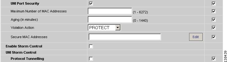
Figure 4-14 UNI Port Security
Step 20
Figure 4-15 Enable Storm Control
Step 21
Figure 4-16 Protocol Tunnelling
For each protocol that you select, enter the shutdown threshold and drop threshold for that protocol:
a.
b.
c.
d.
e.
f.
g.
h.
i.
j.
Step 22
Step 23
The maximum transmission unit (MTU) size is configurable and optional. The default size is 9216, and the range is 1500 to 9216. ISC does not perform an integrity check for this customized value. If a service request goes to the Failed Deploy state because this size is not accepted, you must adjust the size until the Service Request is deployed.
In ISC 4.1, different platforms support different ranges.
•
•
•
Step 24
Step 25
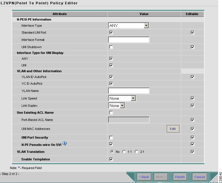
Defining an Ethernet EWS Policy without a CE
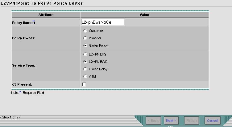
This section describes how to define an Ethernet EWS policy without a CE present. Figure 4-17 is an example of the first page of this policy.
Figure 4-17 Ethernet EWS Policy without a CE
Perform the following steps.
Step 1
The Editable check box gives you the option of making a field editable. If you select the Editable check box, the service operator who is using this L2VPN policy can modify the editable parameter during L2VPN service request creation.
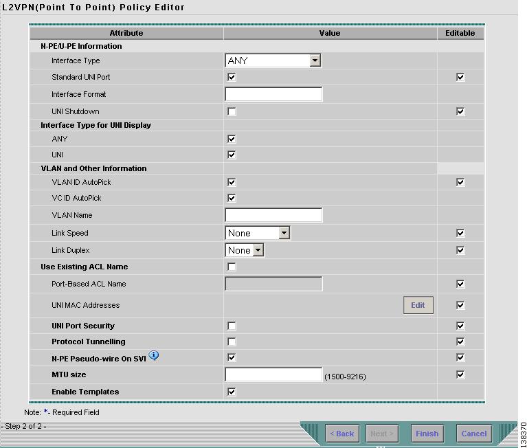
Figure 4-18 Ethernet EWS without CE Policy Attributes
Step 2
You can choose to select a particular interface as a CE, N-PE, or U-PE interface based on the service provider's POP design. The interfaces are:
•
•
•
•
•
•
•
The value defined here functions as a filter to restrict the interface types an operator can see during L2VPN service request creation.
Step 3
Step 4
This is especially useful to specify here if you know that the link will always go through a particular interface's slot/port location on all or most of the network devices in the service.
Step 5
•
•
If DEFAULT is the CE encapsulation type, ISC shows another field for the UNI port type.
Note
Step 6
Step 7
Step 8
Step 9
Step 10
Step 11
Step 12
Step 13
Step 14
Step 15
Step 16
Step 17
a.
b.
c.
•
•
•
d.
Figure 4-19 UNI Port Security
Step 18
Figure 4-20 Enable Storm Control
Step 19
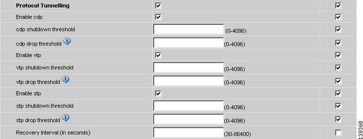
Figure 4-21 Protocol Tunnelling
For each protocol that you check, enter the shutdown threshold and drop threshold for that protocol:
a.
b.
c.
d.
e.
f.
g.
h.
i.
j.
Step 20
Step 21
The maximum transmission unit (MTU) size is configurable and optional. The default size is 9216, and the range is 1500 to 9216. ISC does not perform an integrity check for this customized value. If a service request goes to the Failed Deploy state because this size is not accepted, you must adjust the size until the Service Request is deployed.
In ISC 4.1, different platforms support different ranges.
•
•
•
Step 22
Step 23
Defining a Frame Relay Policy with a CE
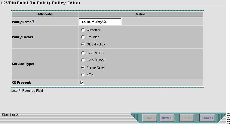
This section describes how to define a Frame Relay policy with CE present. Figure 4-22 is an example of the first page of this policy.
Figure 4-22 Frame Relay Policy with a CE
Perform the following steps:
Step 1
The Editable check box gives you the option of making a field editable. If you select the Editable check box, the service operator who is using this L2VPN policy can modify the editable parameter during L2VPN service request creation.
Figure 4-23 Frame Relay with CE Policy Attributes
Step 2
•
•
Step 3
•
•
•
•
•
Step 4
This is especially useful to specify here if you know that the link will always go through a particular interface's slot/port location on all or most of the network devices in the service.
Step 5
•
•
Note
Step 6
Step 7
Step 8
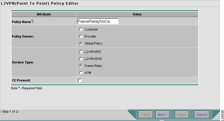
Defining a Frame Relay Policy without a CE
This section describes how to define a Frame Relay policy without a CE present. Figure 4-24 is an example of the first page of this policy.
Figure 4-24 Frame Relay Policy without a CE
Perform the following steps.
Step 1
The Editable check box gives you the option of making a field editable. If you select the Editable check box, the service operator who is using this L2VPN policy can modify the editable parameter during L2VPN service request creation.
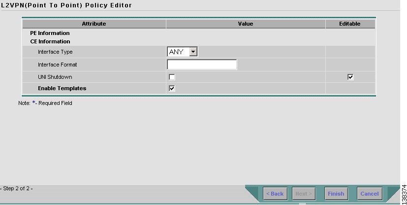
Figure 4-25 Frame Relay without CE Policy Attributes
Step 2
•
•
•
•
•
Step 3
This is especially useful to specify here if you know that the link will always go through a particular interface's slot/port location on all or most of the network devices in the service.
Step 4
•
•
Note
Step 5
Step 6
Step 7
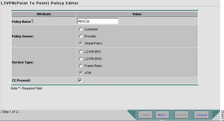
Defining an ATM Policy with a CE
This section describes how to define an AMT policy with CE present. Figure 4-26 is an example of the first page of this policy.
Figure 4-26 ATM Policy with a CE
Perform the following steps.
Step 1
The Editable check box gives you the option of making a field editable. If you select the Editable check box, the service operator who is using this L2VPN policy can modify the editable parameter during L2VPN service request creation.
Figure 4-27 ATM with CE Policy Attributes
Step 2
•
•
Step 3
•
•
•
Step 4
This is especially useful to specify here if you know that the link will always go through a particular interface's slot/port location on all or most of the network devices in the service.
Step 5
•
•
•
•
Note
Step 6
Step 7
Step 8
Defining an ATM Policy without a CE
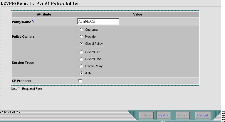
This section describes how to define an AMT policy without a CE present. Figure 4-28 is an example of the first page of this policy.
Figure 4-28 ATM Policy without a CE
Perform the following steps.
Step 1
The Editable check box gives you the option of making a field editable. If you select the Editable check box, the service operator who is using this L2VPN policy can modify the editable parameter during L2VPN service request creation.
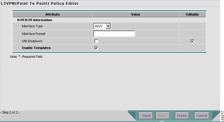
Figure 4-29 ATM without CE Policy Attributes
Step 2
•
•
•
Step 3
This is especially useful to specify here if you know that the link will always go through a particular interface's slot/port location on all or most of the network devices in the service.
Step 4
•
•
Note
Step 5
Step 6
Step 7