-
Cisco IP Solution Center L2VPN User Guide, 4.1
-
Index
-
About This Guide
-
Getting Started with L2VPN
-
ISC L2VPN and VPLS Concepts
-
Setting Up the ISC Service
-
Creating an L2VPN Policy
-
Managing an L2VPN Service Request
-
Creating an L2TPv3 Policy
-
Managing an L2TPv3 Service Request
-
Creating a VPLS Policy
-
Managing a VPLS Service Request
-
Using Autodiscovery for L2 Services
-
Generating L2 and VPLS Reports
-
Deploying, Monitoring and Auditing Service Requests
-
Setting Up VLAN Translation
-
 Feedback
Table Of Contents
Defining a Frame Relay Policy with a CE
Defining a Frame Relay Policy without a CE
Defining an ATM Policy with aCE
Defining an ATM Policy without a CE
Creating an L2TPv3 Policy
This chapter contains the basic steps to create an L2TPv3 policy. It contains the following sections:
•
Defining a Frame Relay Policy with a CE
•
•
•
Defining an L2TPv3 Policy
You must define an L2TPv3 policy before you can provision a Cisco IP Solution Center (ISC) L2TPv3-based L2VPN service. An L2TPv3 policy defines the common characteristics shared by the end-to-end wire attributes and Attachment Circuit (AC) attributes.
A policy can be shared by one or more service requests that have similar service requirements. The Editable check box gives the network operator the option of making a field editable. If the value is set to editable, the service request creator can change to other valid values for the particular policy item. If the value is not set to editable, the service request creator cannot change the policy item.
The two major categories of an L2TPv3 policy correspond to the two major services that L2TPv3 provides:
•
•
A policy is a template of most of the parameters needed to define an L2TPv3 service request. After you define it, an L2TPv3 policy can be used by all the L2TPv3 service requests that share a common set of characteristics.
You create a new L2TPv3 policy whenever you create a new type of service or a service with different parameters. L2TPv3 policy creation is normally performed by experienced network engineers.
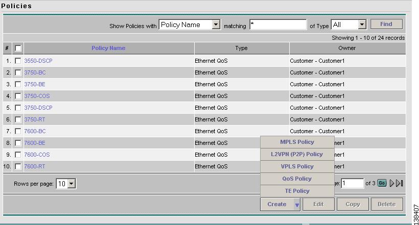
To define an L2TPv3 policy in ISC, perform the following steps.
Step 1
Figure 6-1 Creating an L2TPv3 Policy
Step 2
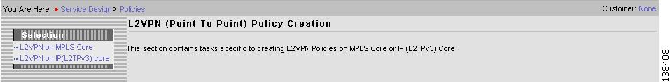
Step 3
Figure 6-2 L2VPN Policy Window
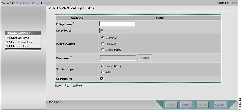
Step 4
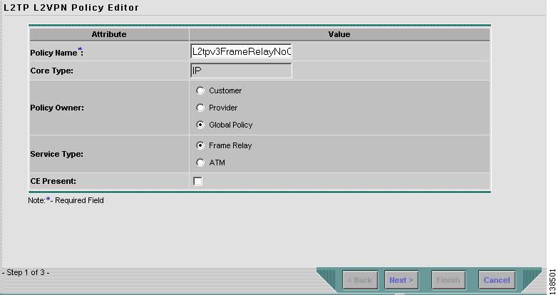
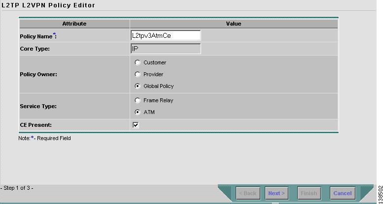
Figure 6-3 L2TP L2VPN Policy Editor
Step 5
Step 6
There are three types of L2TPv3 policy ownership:
•
•
•
This ownership has relevance when the ISC Role-Based Access Control (RBAC) comes into play. For example, an L2TPv3 policy that is customer-owned can only be seen by operators who are allowed to work on this customer-owned policy.
Similarly, operators who are allowed to work on a provider's network can view, use, and deploy a particular provider-owned policy.
Step 7
Step 8
There are two service types for L2TPv3 policies:
•
•
Step 9
If you do not select the CE Present check box, ISC asks the service operator, during service activation, only for the PE router and customer-facing interface.
Step 10
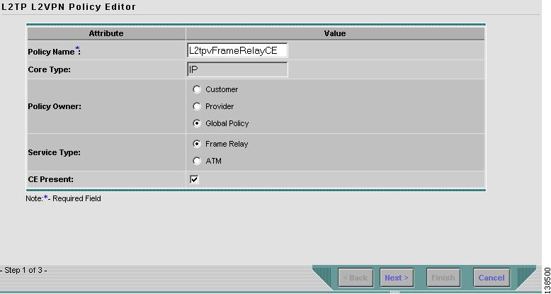
Defining a Frame Relay Policy with a CE
This section describes defining a Frame Relay policy with a CE present. Figure 6-4 is an example of the first page of this policy.
Figure 6-4 Frame Relay Policy with a CE
Step 1
The Editable check box gives you the option of making a field editable. If you select the Editable check box, the service operator who is using this L2TPv3 policy can modify the editable parameter during L2TPv3 service request creation.
Figure 6-5 Frame Relay Policy with a CE Attributes
Step 2
•
We recommend Dynamic.
•
–
–
–
Static L2TPv3 sessions for a PE router configure fixed values for the fields in the L2TP data header. A static L2TPv3 session allows the PE to tunnel Layer 2 traffic as soon as the end-to-end wire to which the session is bound comes up.
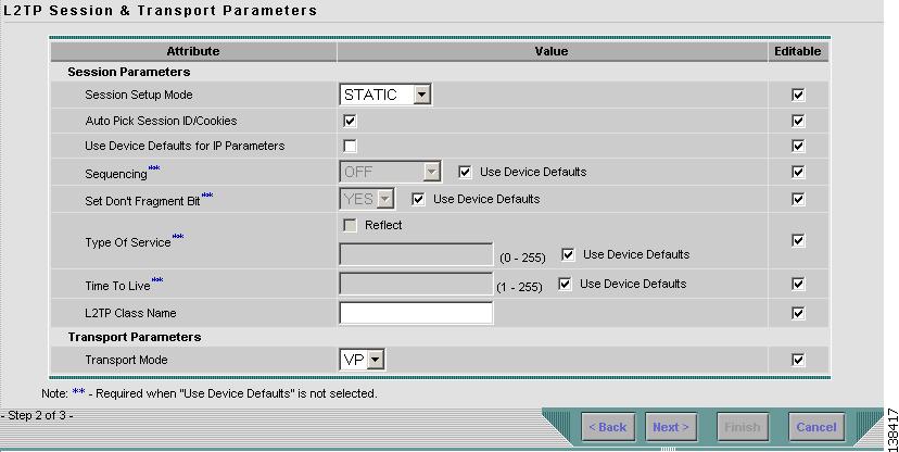
If you choose Static, the Auto Pick Session ID/Cookies check box will appear. See Figure 6-6. If you do not select the Auto Pick Session ID/Cookies check box, ISC will require you to enter the size of the local cookie in bytes and the Session ID when you create a service request for this policy.
Figure 6-6 Static Session Setup Mode
Step 3
Step 4
•
•
•
•
Step 5
Step 6
Step 7
Step 8
Step 9
Step 10
•
•
Step 11
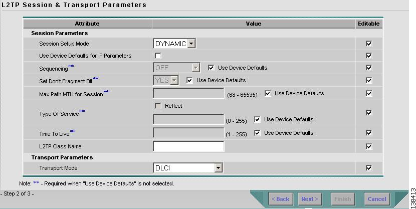
Figure 6-7 Frame Relay Interface with a CE Attributes
Step 12
•
•
Step 13
•
•
For DCLI transport mode, set BOTH PEs to DCE or BOTH to DTE. If the PE setting is DCE, then ISC provisions the corresponding CE (if there is one) to be DTE. If the PE setting is DTE, then ISC provisions the CE (if there is one) to be DCE.
For PORT_TRUNKING transport mode, set one PE to DTE and the other PE to DCE. If the PE setting is DTE, then ISC provisions the CE (if there is one) to be DCE.
Step 14
Step 15
•
•
•
•
Step 16
Step 17
•
•
Note
Step 18
Step 19
Defining a Frame Relay Policy without a CE
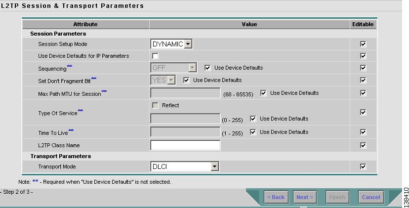
This section describes defining an L2TPv3 Frame Relay policy without a CE present. Figure 6-8 is an example of the first page of this policy.
Figure 6-8 Frame Relay Policy without a CE
Step 1
The Editable check box gives you the option of making a field editable. If you select the Editable check box, the service operator who is using this L2TPv3 policy can modify the editable parameter during L2TPv3 service request creation.
Figure 6-9 Frame Relay without CE Policy Attributes
Step 2
•
We recommend Dynamic.
•
–
–
–
Static L2TPv3 sessions for a PE router configure fixed values for the fields in the L2TP data header. A static L2TPv3 session allows the PE to tunnel Layer 2 traffic as soon as the end-to-end wire to which the session is bound comes up.
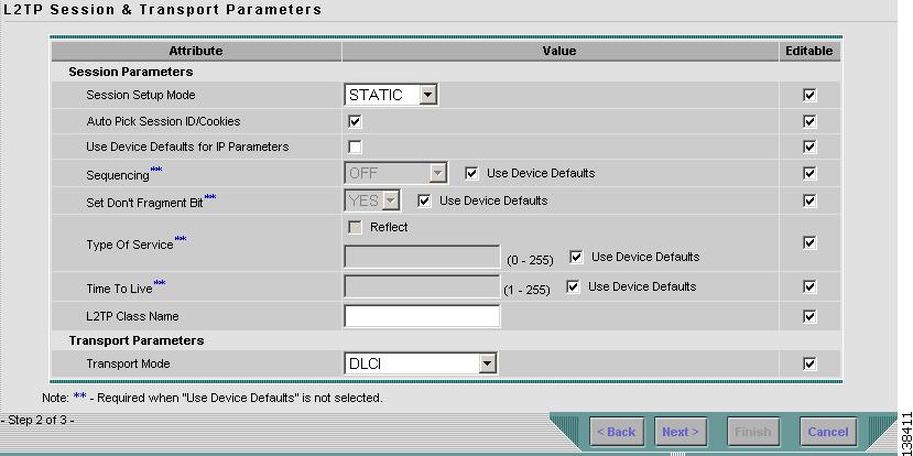
If you choose Static, the Auto Pick Session ID/Cookies check box will appear. See Figure 6-10. If you do not select the Auto Pick Session ID/Cookies check box, ISC will require you to enter the size of the local cookie in bytes and the Session ID when you create a service request for this policy.
Figure 6-10 Static Session Setup Mode
Step 3
Step 4
•
•
•
•
Step 5
Step 6
Step 7
Step 8
Step 9
You must set up a tunnel name on two routers with same name. You can only have one tunnel per PE p air, but there can be many sessions in tunnel.
Step 10
•
•
Step 11
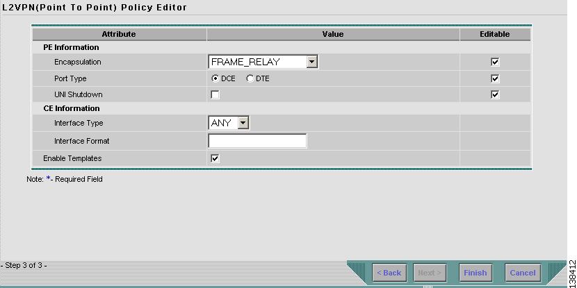
Figure 6-11 PE Frame Relay without a CE
Step 12
•
•
•
•
Step 13
Step 14
•
•
For DCLI transport mode, set BOTH PEs to DCE or BOTH to DTE. If the PE setting is DCE, then ISC provisions the corresponding CE (if there is one) to be DTE. If the PE setting is DTE, then ISC provisions the CE (if there is one) to be DCE.
For PORT_TRUNKING transport mode, set one PE to DTE and the other PE to DCE. If the PE setting is DTE, then ISC provisions the CE (if there is one) to be DCE.
Step 15
Step 16
Step 17
Defining an ATM Policy with aCE
This section describes how to define an L2TPv3 ATM policy with CE present. Figure 6-12 is an example of the first page of this policy.
Figure 6-12 ATM Policy with a CE
Perform the following steps.
Step 1
The Editable check box gives you the option of making a field editable. If you select the Editable check box, the service operator who is using this L2TPv3 policy can modify the editable parameter during L2TPv3 service request creation.
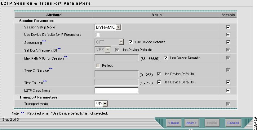
Figure 6-13 ATM Policy with CE Attributes
Step 2
•
We recommend Dynamic.
•
–
–
–
Static L2TPv3 sessions for a PE router configure fixed values for the fields in the L2TP data header. A static L2TPv3 session allows the PE to tunnel Layer 2 traffic as soon as the end-to-end wire to which the session is bound comes up.
If you choose Static, the Auto Pick Session ID/Cookies check box will appear. See Figure 6-14. If you do not select the Auto Pick Session ID/Cookies check box, ISC will require you to enter the size of the local cookie in bytes and the Session ID when you create a service request for this policy.
Figure 6-14 Static Session Setup Mode
Step 3
Step 4
•
•
•
•
Step 5
Step 6
Step 7
Step 8
Step 9
You must set up a tunnel name on two routers with same name. You can only have one tunnel per PE p air, but there can be many sessions in tunnel. For ATM, the vpi/vci pair for CE must match the vpi/vci pair for PE.
Step 10
•
•
Step 11
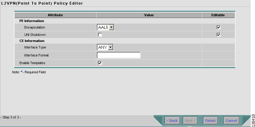
Figure 6-15 ATM with a CE Policy Attributes
Step 12
•
•
Step 13
Step 14
•
•
Step 15
This is especially useful to specify here if you know that the link will always go through a particular interface's slot/port location on all or most of the network devices in the service.
Step 16
•
•
•
•
Note
Step 17
Step 18
Defining an ATM Policy without a CE
This section describes defining an ATM policy without a CE present. Figure 6-16 is an example of the first page of this policy.
Figure 6-16 ATM Policy without a CE
Step 1
The Editable check box gives you the option of making a field editable. If you select the Editable check box, the service operator who is using this L2TPv3 policy can modify the editable parameter during L2TPv3 service request creation.
Figure 6-17 ATM without a CE Policy Attributes
Step 2
•
We recommend Dynamic.
•
–
–
–
Static L2TPv3 sessions for a PE router configure fixed values for the fields in the L2TP data header. A static L2TPv3 session allows the PE to tunnel Layer 2 traffic as soon as the end-to-end wire to which the session is bound comes up.
If you choose Static, the Auto Pick Session ID/Cookies check box will appear. See Figure 6-18. If you do not select the Auto Pick Session ID/Cookies check box, ISC will require you to enter the size of the local cookie in bytes and the Session ID when you create a service request for this policy.
Figure 6-18 Static Session Setup Mode
Step 3
Step 4
•
•
•
•
Step 5
Step 6
Step 7
•
•
Step 8
Step 9
You must set up a tunnel name on two routers with same name. You can only have one tunnel per PE p air, but there can be many sessions in tunnel. For ATM, the vpi/vci pair for CE must match the vpi/vci pair for PE.
Step 10
•
•
Step 11
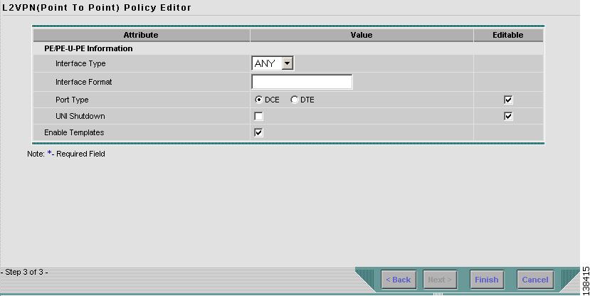
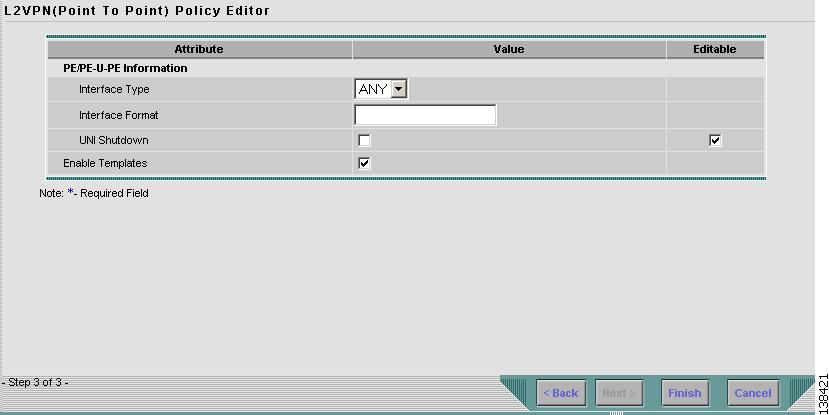
Figure 6-19 ATM PE Policy Information
Step 12
•
•
Step 13
This is especially useful to specify here if you know that the link will always go through a particular interface's slot/port location on all or most of the network devices in the service.
Step 14
Step 15
Step 16