-
Cisco 10000 Series Router Software Configuration Guide
-
About This Guide
-
Broadband Aggregation and Leased-Line Overview
-
Scalability and Performance
-
Configuring Remote Access to MPLS VPN
-
Configuring Multiprotocol Label Switching
-
Configuring the Layer 2 Tunnel Protocol Access Concentrator and Network Server
-
Configuring PPPoE over Ethernet and IEEE 802.1Q VLAN
-
Configuring IP Unnumbered on IEEE 802.1Q VLANs
-
Configuring ATM Permanent Virtual Circuit Autoprovisioning
-
Configuring the Multihop Feature
-
Configuring Address Pools
-
Configuring Local AAA Server, User Database--Domain to VRF
-
Configuring Traffic Filtering
-
Unicast Reverse Path Forwarding
-
Configuring Automatic Protection Switching
-
Configuring IP Multicast
-
Configuring RADIUS Features
-
Cisco 10000 Series Router PXF Stall Monitor
-
SSO - BFD
-
Configuring Link Noise Monitoring
-
Configuring L2 Virtual Private Networks
-
Configuring L2VPN Interworking
-
Configuring Multilink Point-to-Point Protocol Connections
-
Configuring Gigabit EtherChannel Features
-
Configuring IP Version 6
-
Configuring Template ACLs
-
Protecting the Router from DoS Attacks
-
IP Tunneling
-
RADIUS Attributes
-
Glossary
-
 Feedback
Table Of Contents
Configuring PPPoE over Ethernet and IEEE 802.1Q VLAN
Feature History for PPPoE over Ethernet
Restrictions for PPPoE over Ethernet
Configuration Tasks for PPPoE over Ethernet
Configuring a Virtual Template Interface
Creating an Ethernet Interface and Enabling PPPoE
Configuring PPPoE in a VPDN Group
Configuring PPPoE in a BBA Group
Configuration Example for PPPoE over Ethernet
Feature History for Static MAC Address for PPPoE
Feature History for PPPoE over IEEE 802.1Q VLANs
Restrictions for PPPoE over IEEE 802.1Q VLANs
Configuration Tasks for PPPoE over IEEE 802.1Q VLANs
Configuring a Virtual Template Interface
Creating an Ethernet 802.1Q Encapsulated Subinterface and Enabling PPPoE
Configuring PPPoE in a VPDN Group
Configuring PPPoE in a BBA Group
Configuration Examples for PPPoE over IEEE 802.1Q VLANs
Verifying PPPoE over Ethernet and IEEE 802.1Q VLAN
Feature History for TCP MSS Adjust
Information about TCP MSS Adjust
Restrictions for TCP MSS Adjust
Configuration Task for TCP MSS Adjust
TCP MSS Adjustment Configuration: Examples
Feature History for VLAN Range
Configuration Task for VLAN Range
Configuring a Range of VLAN Subinterfaces
Configuration Examples for VLAN Range
Verifying the Configuration of a Range of Subinterfaces
Configuring PPPoE over Ethernet and IEEE 802.1Q VLAN
The Cisco 10000 series router allows the tunneling and termination of PPP sessions over Ethernet links. The PPPoE over Ethernet interface (PPPoEoE) feature enables the Cisco 10000 series router to tunnel and terminate Ethernet PPP sessions over Ethernet links. The PPPoE over IEEE 802.1Q VLANs feature enables the router to tunnel and terminate Ethernet PPP sessions across VLAN links. IEEE 802.1Q encapsulation is used to interconnect a VLAN-capable router with another VLAN-capable networking device. The packets on the 802.1Q link contain a standard Ethernet frame and the VLAN information associated with that frame.
This chapter describes the following features:
For more information, see the "Configuring Broadband Access: PPP and Routed Bridge Encapsulation" chapter in the Cisco IOS Wide-Area Networking Configuration Guide and the VLAN Range, Release 12.2(13)T feature guide.
PPPoE over Ethernet
The PPPoE over Ethernet feature provides the ability to connect a network of hosts over a simple bridging access device to a remote Access Concentrator. The Cisco 10000 series router supports PPPoE over Ethernet sessions to enable multiple hosts on a shared Ethernet interface to open PPP sessions to the PPPoE server.
The PPPoE over Ethernet feature is described in the following topics:
•
Feature History for PPPoE over Ethernet
•
•
•
Feature History for PPPoE over Ethernet
Restrictions for PPPoE over Ethernet
The PPPoE over Ethernet feature has the following restriction:
•
Note
Configuration Tasks for PPPoE over Ethernet
To configure the PPPoE over Ethernet feature, perform the following configuration tasks:
•
•
•
•
Configuring a Virtual Template Interface
Configure a virtual template before you configure PPPoE on an Ethernet interface. The virtual template interface is a logical entity that is applied dynamically as needed to an incoming PPP session request. To configure a virtual template interface, see the "Configuring a Virtual Template Interface" section on page 3-17.
Creating an Ethernet Interface and Enabling PPPoE
To create an Ethernet interface and enable PPPoE on it, enter the following commands beginning in global configuration mode:
Configuring PPPoE in a VPDN Group
To configure a virtual private dial network (VPDN) group for PPPoE and to link the group to the appropriate virtual template interface, enter the following commands beginning in global configuration mode:
Note
Configuring PPPoE in a BBA Group
Note
To configure a broadband aggregation (BBA) group for PPPoE and to link it to the appropriate virtual template interface, enter the following commands beginning in global configuration mode:
Note
Configuration Example for PPPoE over Ethernet
Example 6-1 shows a PPPoE over Ethernet configuration. In the example, the virtual template virtual-template 1 is linked to the VPDN group. The configuration also specifies the number of sessions allowed on the VPDN group.
Example 6-1 Using a VPDN Group to Configure PPPoE over Ethernet
!Creates a VPDN session group and links it to a virtual template.vpdn-group 1accept-dialinprotocol pppoevirtual-template 1pppoe limit per-mac 10pppoe limit max-sessions 32000interface Loopback0ip address 172.16.0.1 255.255.255.255!Enables PPPoE and allows PPPoE sessions to be created through this subinterface.interface GigabitEthernet1/0/0no ip addressnegotiation autopppoe enable!Configures the virtual template interface.interface Virtual-Template1ip unnumbered loop 0mtu 1492peer default ip address pool pool1ppp authentication chap!Specifies the IP local pool to use for address assignment.ip local pool pool1 192.168.0.1 192.168.0.100Example 6-2 creates a BBA group named vpn-1 and links it to virtual-template 1. The vpn-1 BBA group is associated with VLAN 20.
Example 6-2 Using a BBA Group to Configure PPPoE over Ethernet
bba-group pppoe vpn-1virtual-template 1sessions per-vc limit 5sessions per-mac limit 10!!interface GigabitEthernet1/0/0.1encapsulation dot1q 20protocol pppoe group vpn-1Static MAC Address for PPPoE
The Static MAC Address for PPPoE feature allows you to choose the MAC address to be used as the source MAC address for PPPoE over ATM sessions on ATM permanent virtual circuits (PVCs). You can configure this feature for either a broadband aggregation (BBA) group or a virtual private dialup network (VPDN) group. The feature is applied to all PPPoEoA sessions on ATM PVCs to which the BBA group or the VPDN group is applied.
Note
The configuration of the Static MAC Address for PPPoE feature for BBA groups and VPDN groups is mutually exclusive. If you configure a MAC address as a source MAC address for a BBA group, a VPDN group cannot use this MAC address as a source MAC address for the VPDN group. To apply the BBA group MAC address to a VPDN group, you must manually configure the Static MAC Address for PPPoE feature for the VPDN group as well.
Example 6-3 shows how you can throttle PPP sessions using the MAC address. This example allows a maximum of five sessions from each MAC address. If more than five sessions are attempted from this MAC address, any sessions using that particular MAC address are throttled for 30 seconds.
Example 6-3 Throttling PPP Sessions Using the MAC Address
bba-group pppoe PPPoEvirtual-template 1sessions per-vc limit 32000sessions per-mac limit 32000sessions per-mac throttle 5 1 30To get a list of the throttled MAC addresses, use the show pppoe throttled mac command in privileged EXEC mode:
Router# show pppoe throttled macMAC(s) throttledMAC Ingress Port00c1.00aa.006c ATM1/0/0.101007c.009e.0070 ATM1/0/0.1010097.009d.007a ATM1/0/0.101008c.0077.0082 ATM1/0/0.10100b5.00a8.009f ATM1/0/0.10100a4.0088.00b5 ATM1/0/0.101Feature History for Static MAC Address for PPPoE
PPPoE over IEEE 802.1Q VLANs
The PPPoE over IEEE 802.1Q VLANs feature enables the Cisco 10000 series router to support PPPoE over IEEE 802.1Q encapsulated VLAN interfaces. IEEE 802.1Q encapsulation is used to interconnect a VLAN-capable router with another VLAN-capable networking device. The packets on the 802.1Q link contain a standard Ethernet frame and the VLAN information associated with that frame.
Note
The PPPoE over IEEE 802.1Q VLANs feature is described in the following topics:
•
•
•
•
•
Feature History for PPPoE over IEEE 802.1Q VLANs
Restrictions for PPPoE over IEEE 802.1Q VLANs
The PPPoE over IEEE 802.1Q VLANs feature has the following restrictions:
•
•
Configuration Tasks for PPPoE over IEEE 802.1Q VLANs
To configure the PPPoE over IEEE 802.1Q VLANs feature, perform the following configuration tasks:
•
•
•
•
The following sections describe how to perform these configuration tasks. For more information, see the "Configuring Broadband Access: PPP and Routed Bridge Encapsulation" chapter in the Cisco IOS Wide-Area Networking Configuration Guide.
Configuring a Virtual Template Interface
Configure a virtual template interface before you configure PPPoE on an IEEE 802.1Q VLAN interface. The virtual template interface is a logical entity that is applied dynamically as needed to a serial interface. To configure a virtual template interface, see the "Configuring a Virtual Template Interface" section on page 3-17.
Creating an Ethernet 802.1Q Encapsulated Subinterface and Enabling PPPoE
To create an Ethernet 802.1Q encapsulated subinterface and enable PPPoE on it, enter the following commands beginning in global configuration mode:
Configuring PPPoE in a VPDN Group
To configure a VPDN group for PPPoE and link it to the appropriate virtual template interface, enter the following commands beginning in global configuration mode:
Note
Configuring PPPoE in a BBA Group
Note
To configure a broadband aggregation (BBA) group for PPPoE and to link it to the appropriate virtual template interface, enter the following commands beginning in global configuration mode:
Note
Configuration Examples for PPPoE over IEEE 802.1Q VLANs
Example 6-4 shows a PPPoE over IEEE 802.1Q encapsulated VLAN configuration. In the example, the virtual-template 1 virtual template is linked to the VPDN group. The configuration also specifies the maximum number of sessions allowed on the VPDN group and the number of sessions allowed for each VLAN.
Example 6-4 Using a VPDN Group to Configure PPPoE over IEEE 802.1Q VLANs
!Enables a virtual private dial-up network configuration on the router.vpdn enable!!Creates a VPDN session group and links it to a virtual template.vpdn-group 1accept-dialinprotocol pppoevirtual-template 1pppoe limit per-mac 10pppoe limit per-vlan 100pppoe limit max-sessions 32000interface Loopback0ip address 172.16.0.1 255.255.255.255interface GigabitEthernet1/0/0no ip addressnegotiation auto!Enables PPPoE and allows PPPoE sessions to be created through this subinterface.interface GigabitEthernet1/0/0.10encapsulation dot1Q 20pppoe enablepppoe max-sessions 10!Configures the virtual template interface.interface Virtual-Template1ip unnumbered loop 0mtu 1492peer default ip address pool pool1ppp authentication chap!Specifies the IP local pool to use for address assignment.ip local pool pool1 192.168.0.1 192.168.0.100Example 6-5 creates two BBA groups: VPN_1 and VPN_2. The VPN_1 BBA group is associated with virtual-template 1 and the VPN_2 BBA group is associated with virtual-template 2. The VPN_1 group is associated with VLAN 20 and the VPN_2 group is associated with VLAN 30.
Example 6-5 Using a BBA Group to Configure PPPoE over IEEE 802.1Q VLANs
bba-group pppoe VPN_1virtual-template 1sessions per-vc limit 5sessions per-mac limit 10sessions per-vlan limit 5!!bba-group pppoe VPN_2virtual-template 2sessions per-vc limit 5sessions per-mac limit 10sessions per-vlan limit 5!!interface GigabitEthernet1/0/0.1encapsulation dot1q 20protocol pppoe group VPN_1!interface GigabitEthernet 2/0/0.2encapsulation dot1q 30protocol pppoe group VPN_2Verifying PPPoE over Ethernet and IEEE 802.1Q VLAN
To verify PPPoE over Ethernet and IEEE 802.1Q VLAN, enter the following commands in privileged EXEC mode:
Clearing PPPoE Sessions
To clear PPPoE sessions, enter the following commands in privileged EXEC mode:
TCP MSS Adjust
The TCP MSS Adjustment feature enables the configuration of the maximum packet segment size (MSS).
When a host (usually a PC) initiates a TCP session with a server, it negotiates the IP segment size by using the MSS option field in the TCP SYN packet. The value of the MSS field is determined by the maximum transmission unit (MTU) configuration on the host. The default MSS value for a PC is 1500 bytes.
The PPP over Ethernet (PPPoE) standard supports a MTU of only 1492 bytes. The disparity between the host and PPPoE MTU size can cause the router in between the host and the server to drop 1500-byte packets and terminate TCP sessions over the PPPoE network. Even if the path MTU (which detects the correct MTU across the path) is enabled on the host, sessions may be dropped because system administrators sometimes disable the ICMP error messages that must be relayed from the host in order for path MTU to work.
In most cases, the optimum value for the max-segment-size argument is 1452 bytes. This value plus the 20-byte IP header, the 20-byte TCP header, and the 8-byte PPPoE header add up to a 1500-byte packet that matches the MTU size for the Ethernet link.
Feature History for TCP MSS Adjust
12.2(31)SB3
This feature was introduced on the Cisco 10000 series router.
PRE2 or PRE3
Information about TCP MSS Adjust
•
•
•
Restrictions for TCP MSS Adjust
•
Configuration Task for TCP MSS Adjust
Perform this task to configure the maximum segment size (MSS) for transient packets that traverse the Cisco 10000 Series router, specifically TCP segments in the SYN bit and to configure the MTU size of IP packets.
SUMMARY STEPS
1.
2.
3.
4.
DETAILED STEPS
TCP MSS Adjustment Configuration: Examples
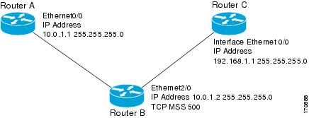
Figure 1 Example Topology for TCP MSS Adjustment
The following example shows how to configure and verify the adjustment value. Configure the interface adjustment value on router B:
Router_B(config)# ip pxf adjust-mss 500Telnet from router A to router C, with B having the MSS adjustment configured.
Router_A# telnet 192.168.1.1Trying 192.168.1.1... OpenObserve the debug output from router C:
Router_C# debug ip tcp transactionsSep 5 18:42:46.247: TCP0: state was LISTEN -> SYNRCVD [23 -> 10.0.1.1(38437)]Sep 5 18:42:46.247: TCP: tcb 32290C0 connection to 10.0.1.1:38437, peer MSS 500, MSS is 500Sep 5 18:42:46.247: TCP: sending SYN, seq 580539401, ack 6015751Sep 5 18:42:46.247: TCP0: Connection to 10.0.1.1:38437, advertising MSS 500Sep 5 18:42:46.251: TCP0: state was SYNRCVD -> ESTAB [23 -> 10.0.1.1(38437)]The MSS gets adjusted to 500 on Router_B as configured.
The following example shows the configuration of a PPPoE client with the MSS value set to 1452:
vpdn enableno vpdn logging!vpdn-group 1request-dialinprotocol pppoeip pxf adjust-mss 1452!interface Ethernet0ip address 192.168.100.1.255.255.255.0ip nat inside!interface ATM0no ip addressno atm ilmi-keepalivepvc 8/35pppoe client dial-pool-number 1!dsl equipment-type CPEdsl operating-mode GSHDSL symmetric annex Bdsl linerate AUTO!interface Dialer1ip address negotiatedip mtu 1492ip nat outsideencapsulation pppdialer pool 1dialer-group 1ppp authentication pap callinppp pap sent-username sohodyn password 7 141B1309000528!ip nat inside source list 101 Dialer1 overloadip route 0.0.0.0.0.0.0.0 Dialer1access-list permit ip 192.168.100.0.0.0.0.255 anyVLAN Range
The VLAN range feature simplifies the configuration of VLAN subinterfaces. By using this feature, you can configure a group of VLAN subinterfaces at one time instead of configuring each subinterface separately. The commands you enter for a group of VLAN subinterfaces apply to each subinterface within the group and are applied to all existing VLANs.
By using the VLAN range feature, you can also configure overlapping ranges of subinterfaces and an individual subinterface within a range of subinterfaces.
The VLAN Range feature is described in the following topics:
•
•
•
•
Feature History for VLAN Range
Restrictions for VLAN Range
The VLAN range feature has the following restrictions:
•
•
•
Configuration Task for VLAN Range
To configure the VLAN range feature, perform the following required configuration task:
•
Configuring a Range of VLAN Subinterfaces
To configure a range of VLAN subinterfaces, enter the following commands beginning in global configuration mode:
Configuration Examples for VLAN Range
Example 6-6 configures the Fast Ethernet subinterfaces with the range 5/1.1 to 5/1.4 and applies the following VLAN IDs to the subinterfaces:
•
•
•
•
Example 6-6 Configuring a Range of VLAN Subinterfaces
Router(config)# interface range fastethernet5/1.1 - fastethernet5/1.4Router(config-if-range)# encapsulation dot1q 301Router(config-if-range)# no shutdownVerifying the Configuration of a Range of Subinterfaces
To verify the configuration of a range of subinterfaces for VLAN encapsulation, enter the following commands in privilege EXEC mode: