-
Cisco 10000 Series Router Software Configuration Guide
-
About This Guide
-
Broadband Aggregation and Leased-Line Overview
-
Scalability and Performance
-
Configuring Remote Access to MPLS VPN
-
Configuring Multiprotocol Label Switching
-
Configuring the Layer 2 Tunnel Protocol Access Concentrator and Network Server
-
Configuring PPPoE over Ethernet and IEEE 802.1Q VLAN
-
Configuring IP Unnumbered on IEEE 802.1Q VLANs
-
Configuring ATM Permanent Virtual Circuit Autoprovisioning
-
Configuring the Multihop Feature
-
Configuring Address Pools
-
Configuring Local AAA Server, User Database--Domain to VRF
-
Configuring Traffic Filtering
-
Unicast Reverse Path Forwarding
-
Configuring Automatic Protection Switching
-
Configuring IP Multicast
-
Configuring RADIUS Features
-
Cisco 10000 Series Router PXF Stall Monitor
-
SSO - BFD
-
Configuring Link Noise Monitoring
-
Configuring L2 Virtual Private Networks
-
Configuring L2VPN Interworking
-
Configuring Multilink Point-to-Point Protocol Connections
-
Configuring Gigabit EtherChannel Features
-
Configuring IP Version 6
-
Configuring Template ACLs
-
Protecting the Router from DoS Attacks
-
IP Tunneling
-
RADIUS Attributes
-
Glossary
-
 Feedback
Table Of Contents
Required Configuration Tasks for Multihop
Enabling VPDN and Multihop Functionality
Terminating the Tunnel from the LAC
Mapping the Ingress Tunnel Name to an LNS
Optional Configuration Tasks for Multihop
Specifying VPDN Tunnel Authorization Searches by Ingress Tunnel Name
Preserving the Type of Service Field of Encapsulated IP Packets
Configuring an Accept-Dialin VPDN Group to Preserve IP TOS
Configuring a Request-Dialout VPDN Group to Preserve IP TOS
Configuration Examples for Multihop
Monitoring and Maintaining Multihop Configurations
Configuring Multihop
In a Virtual Private Dialup Network (VPDN) environment, sessions generated from a remote host are routed over an existing tunnel or a tunnel built to route a specific domain. Typically, sessions cannot traverse more than one L2TP tunnel before reaching the ISP or corporate network. However, by using the Multihop feature, you can configure the Cisco 10000 series router to terminate sessions arriving in L2TP tunnels from a LAC and then route the remote traffic through new L2TP tunnels to an LNS device in the ISP or corporate network.
The Multihop feature enables the Cisco 10000 series router to terminate sessions arriving in L2TP tunnels from a LAC and to forward the sessions through new L2TP tunnels to the router's peer L2TP Network Server (LNS). The packets arrive at the router with L2TP encapsulation and the router forwards the packets with a different L2TP encapsulation. The Cisco 10000 router maps the sessions to the new tunnels based on the session's domain or the tunnel in which the session arrived.
The Cisco 10000 router also supports the preservation of the IP type of service (TOS) field for tunneled IP packets. Each L2TP data packet and IP packet has a TOS field. When the router creates an L2TP data packet, the TOS field sets to zero (normal service), ignoring the TOS field of the encapsulated IP packet being tunneled. To preserve quality of service for tunneled packets, the Cisco 10000 router supports the configuration of accept-dialin and request-dialout VPDN groups using the l2tp ip tos reflect command. When the router creates an L2TP data packet at a virtual-access interface (VAI), instead of ignoring the IP packet TOS field, the router copies the field onto the L2TP data packet.
Note
Typically, the Cisco IOS software reflects the TOS field from the inner packet header to the outer packet header. However, the Cisco 10000 router propagates the TOS field from the ingress header to the egress header.
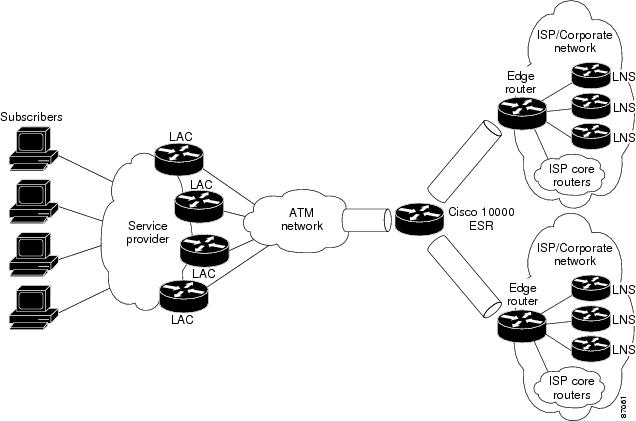
Figure 9-1 shows an example of a multihop topology. On the access network side, the Cisco 10000 router connects to access provider LACs. On the provider network side, the router connects to LNS devices in other ISP or corporate provider networks. Multiple L2TP tunnels are carried over either multiple interfaces or a single interface. Typically, the connection between the router and the LAC or the router and the LNS is an ATM connection. However, this is not a requirement. You can use any interface that can carry L2TP tunneled traffic.
Figure 9-1 Multihop Topology Example
This chapter describes the Multihop feature in the following topics:
•
•
•
•
Feature History for Multihop
Restrictions for Multihop
The Multihop feature has the following restrictions:
•
•
•
•
•
To preserve the IP TOS field of tunneled IP packets, the following restrictions apply:
•
•
•
Required Configuration Tasks for Multihop
To configure the Multihop feature on the Cisco 10000 router, perform the following configuration tasks:
•
•
•
Enabling VPDN and Multihop Functionality
To enable VPDN and multihop functionality, enter the following commands in global configuration mode:
Step 1
Router(config)# vpdn enable
Enables VPDN functionality.
Step 2
Router(config)# vpdn multihop
Enables VPDN multihop functionality.
Terminating the Tunnel from the LAC
To terminate the tunnel from the LAC, enter the following commands beginning in global configuration mode:
Mapping the Ingress Tunnel Name to an LNS
To map the ingress tunnel name to an LNS, enter the following commands beginning in global configuration mode:
Optional Configuration Tasks for Multihop
To configure the Multihop feature on the Cisco 10000 router, perform any of the following optional tasks:
•
•
Specifying VPDN Tunnel Authorization Searches by Ingress Tunnel Name
To specify that the provider's network access server is to perform VPDN tunnel authorization searches by using the ingress tunnel name, enter the following command in global configuration mode:
Router (config)# vpdn search-order multihop-hostname [domain]
Specifies a search by the configured ingress tunnel name.
Optionally, you can specify to search by domain name only.
Preserving the Type of Service Field of Encapsulated IP Packets
To preserve the type of service (TOS) field of encapsulated IP packets, perform the following configuration tasks:
•
•
Configuring an Accept-Dialin VPDN Group to Preserve IP TOS
To configure an accept-dialin VPDN group to preserve IP TOS, enter the following commands beginning in global configuration mode:
Example 9-1 configures vpdn-group 1 to accept tunneled PPP connections from the remote LAC named myhost and to preserve the TOS field of L2TP tunneled IP packets.
Example 9-1 Configuring an Accept-Dialin VPDN Group for IP TOS Preservation
vpdn-group 1accept-dialinprotocol l2tpvirtual-template 1terminate-from hostname myhostlocal name local-host1ip tos reflectConfiguring a Request-Dialout VPDN Group to Preserve IP TOS
To configure a request-dialout VPDN group to preserve IP TOS, enter the following commands beginning in global configuration mode:
Example 9-2 configures vpdn-group 1 for L2TP dialout tunnel preservation of the IP TOS.
Example 9-2 Configuring a Request-Dialout VPDN Group for IP TOS Preservation
vpdn-group 1request-dialoutprotocol l2tppool-member 1initiate-to ip 10.16.49.94ip tos reflectConfiguration Examples for Multihop
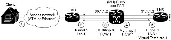
The example in this section is a multihop configuration in which the Cisco 10000 router is configured as the multihop system (MH). The example includes LAC and LNS configurations to complete the configuration. This configuration scenario supports a maximum of two hops between the LAC device and the destination LNS device.
Figure 9-2 shows the example multihop configuration, described in more detail in the list that follows.
Figure 9-2 Multihop Configuration Example
The remote client dials in to the LAC. The LAC negotiates link control protocol (LCP) and preauthenticates the user.
5.
6.
7.
8.
LAC Configuration
!vpdn enable!vpdn-group tunnel1request-dialinprotocol l2tpdomain cisco.cominitiate-to ip 30.1.1.2 priority 1local name LAC1l2tp tunnel password 7 060A0E23l2tp tunnel receive-window 100l2tp tunnel retransmit timeout min 2!Multihop Configuration
username user@cisco.com password 0 lab!vpdn enablevpdn multihopvpdn search-order multihop-hostname domain dnis!vpdn-group multihop0accept-dialinprotocol l2tpterminate-from hostname LAC1local name HGW1l2tp tunnel password 7 09404F0B!vpdn-group multihop1request-dialinprotocol l2tpmultihop hostname LAC1initiate-to ip 31.1.1.2 priority 1local name HGW1l2tp tunnel password 7 0507070D!LNS Configuration
vpdn enable!vpdn-group tunnel1accept-dialinprotocol l2tpvirtual-template 1terminate-from hostname HGW1local name LNS1l2tp tunnel password 7 04570A04l2tp tunnel receive-window 100l2tp tunnel retransmit timeout min 2!interface Virtual-Template1ip unnumbered GigabitEthernet2/0/0no keepalivepeer default ip address pool pool-1ppp mtu adaptiveppp authentication pap callin!ip local pool pool-1 4.2.0.0 4.2.255.255Monitoring and Maintaining Multihop Configurations
To monitor and maintain multihop configurations and VPDN groups, enter the following commands in privileged EXEC mode:
Caution
Example 9-3 shows the information that displays when you use the show vpdn command. All tunnel and session information displays for all active sessions and tunnels when you use the show vpdn command without any keywords or arguments.
Example 9-3 show vpdn Command
Router# show vpdnL2TP Tunnel and Session Information Total tunnels 2 sessions 22LocID RemID Remote Name State Remote Address Port Sessions VPDN Group12060 19602 tunnel5 est 45.1.5.5 1701 11 tunnel5LocID RemID TunID Intf Username State Last Chg3 3 12060 SSS Circuit u@n5 est 2d19h2 2 12060 SSS Circuit u@n5 est 2d19h4 4 12060 SSS Circuit u@n5 est 2d19h5 5 12060 SSS Circuit u@n5 est 2d19h6 6 12060 SSS Circuit u@n5 est 2d19h7 7 12060 SSS Circuit u@n5 est 2d19h8 8 12060 SSS Circuit u@n5 est 2d19h9 9 12060 SSS Circuit u@n5 est 2d19h10 10 12060 SSS Circuit u@n5 est 2d19h11 11 12060 SSS Circuit u@n5 est 2d19h12 12 12060 SSS Circuit u@n5 est 2d19hLocID RemID Remote Name State Remote Address Port Sessions VPDN Group10335 2883 tunnel6 est 45.1.6.5 1701 11 tunnel6LocID RemID TunID Intf Username State Last Chg14 14 10335 SSS Circuit u@n6 est 2d19h15 15 10335 SSS Circuit u@n6 est 2d19h16 16 10335 SSS Circuit u@n6 est 2d19h17 17 10335 SSS Circuit u@n6 est 2d19h18 18 10335 SSS Circuit u@n6 est 2d19h19 19 10335 SSS Circuit u@n6 est 2d19h20 20 10335 SSS Circuit u@n6 est 2d19h21 21 10335 SSS Circuit u@n6 est 2d19h22 22 10335 SSS Circuit u@n6 est 2d19h23 23 10335 SSS Circuit u@n6 est 2d19h13 13 10335 SSS Circuit u@n6 est 2d19h%No active L2F tunnels%No active PPTP tunnels%No active PPPoE tunnelsExample 9-4 uses the show interface virtual-access command to display information about virtual access interface 3. In this example, the following information indicates a normal working status:
Virtual-Access3 is up, line protocol is upExample 9-4 show interface virtual access Command
Router# show interface virtual-access 3Virtual-Access3 is up, line protocol is upHardware is Virtual Access interfaceMTU 1500 bytes, BW 128 Kbit, DLY 100000 usec, rely 255/255, load 1/255Encapsulation PPP, loopback not set, keepalive set (10 sec)DTR is pulsed for 5 seconds on resetLCP Open, multilink OpenOpen: IPCPLast input 00:02:30, output never, output hang neverLast clearing of "show interface" counters 1d19hQueueing strategy: fifoOutput queue 0/40, 0 drops; input queue 21/75, 0 drops5 minute input rate 0 bits/sec, 0 packets/sec5 minute output rate 0 bits/sec, 0 packets/sec55930 packets input, 3347967 bytes, 0 no bufferReceived 0 broadcasts, 0 runts, 0 giants, 0 throttles0 input errors, 0 CRC, 0 frame, 0 overrun, 0 ignored, 0 abort105261 packets output, 9607052 bytes, 0 underruns0 output errors, 0 collisions, 0 interface resets0 output buffer failures, 0 output buffers swapped out0 carrier transitions