-
Cisco 10000 Series Router Software Configuration Guide
-
About This Guide
-
Broadband Aggregation and Leased-Line Overview
-
Scalability and Performance
-
Configuring Remote Access to MPLS VPN
-
Configuring Multiprotocol Label Switching
-
Configuring the Layer 2 Tunnel Protocol Access Concentrator and Network Server
-
Configuring PPPoE over Ethernet and IEEE 802.1Q VLAN
-
Configuring IP Unnumbered on IEEE 802.1Q VLANs
-
Configuring ATM Permanent Virtual Circuit Autoprovisioning
-
Configuring the Multihop Feature
-
Configuring Address Pools
-
Configuring Local AAA Server, User Database--Domain to VRF
-
Configuring Traffic Filtering
-
Unicast Reverse Path Forwarding
-
Configuring Automatic Protection Switching
-
Configuring IP Multicast
-
Configuring RADIUS Features
-
Cisco 10000 Series Router PXF Stall Monitor
-
SSO - BFD
-
Configuring Link Noise Monitoring
-
Configuring L2 Virtual Private Networks
-
Configuring L2VPN Interworking
-
Configuring Multilink Point-to-Point Protocol Connections
-
Configuring Gigabit EtherChannel Features
-
Configuring IP Version 6
-
Configuring Template ACLs
-
Protecting the Router from DoS Attacks
-
IP Tunneling
-
RADIUS Attributes
-
Glossary
-
 Feedback
Table Of Contents
Configuring L2 Virtual Private Networks
Supported L2VPN Transport Types
Checkpointing AToM Information
Checkpointing Troubleshooting Tips
Prerequisites for NSF/SSO - L2VPN
Neighbor Routers in the MPLS HA Environment
Nonstop Forwarding for Routing Protocols
Restrictions for NSF/SSO - L2VPN
Configuration Examples of NSF/SSO—Layer 2 VPN
L2VPN Local Switching—HDLC/PPP
Prerequisites of L2VPN Local Switching—HDLC/PPP
Restrictions of L2VPN Local Switching—HDLC/PPP
PPP Like-to-Like Local Switching
HDLC Like-to-Like Local Switching
Configuration Tasks and Examples
Setting Up the Pseudowire—AToM Circuit
Configuring ATM AAL5 SDU Support over MPLS
Verifying ATM AAL5 SDU Support over MPLS
Configuring ATM-to-ATM PVC Local Switching
Configuring OAM Cell Emulation for ATM AAL5 SDU Support over MPLS
Configuring OAM Cell Emulation for ATM AAL5 SDU Support over MPLS on PVCs
Configuring OAM Cell Emulation for ATM AAL5 SDU Support over MPLS in VC Class Configuration Mode
Configuring Ethernet over MPLS
Ethernet over MPLS Restrictions
Configuring Ethernet over MPLS in VLAN Mode
Configuring Ethernet over MPLS in Port Mode
IEEE 802.1Q Tunneling for AToM—QinQ
Prerequisites for IEEE 802.1Q Tunneling (QinQ) for AToM
Restrictions for IEEE 802.1Q Tunneling (QinQ) for AToM
Restrictions for Configuring Remote Ethernet Port Shutdown
Configuring Remote Ethernet Port Shutdown
Configuring Ethernet over MPLS with VLAN ID Rewrite
Configuring Frame Relay over MPLS
Configuring Frame Relay over MPLS with DLCI-to-DLCI Connections
Configuring Frame Relay over MPLS with Port-to-Port Connections
Enabling Other PE Devices to Transport Frame Relay Packets
Configuring Frame Relay-to-Frame Relay Local Switching
Configuring Frame Relay for Local Switching
Configuring Frame Relay Same-Port Switching
Verifying Layer 2 Local Switching for Frame Relay
Configuring HDLC and PPP over MPLS
Restrictions for HDLC over MPLS
Restrictions for PPP over MPLS
Configuring HDLC over MPLS or PPP over MPLS
Estimating the Size of Packets Traveling Through the Core Network
Estimating Packet Size—Example
Changing the MTU Size on P and PE Routers
Setting Experimental Bits with AToM
Monitoring and Maintaining L2VPN
Configuration Example—Frame Relay over MPLS
Any Transport over MPLS—Tunnel Selection
Configuration Example—Any Transport over MPLS: Tunnel Selection
Configuring L2 Virtual Private Networks
To improve profitability, service providers (SPs) introduce new services to reduce operational expenditures. To reduce the number of managed networks, use network convergence, a multiphase transition of the network. This affects both the core and edge/aggregation side. The technology is predominantly Multiprotocol Label Switching (MPLS) based core networks. However, IP cores are the service of choice in a number of large SPs. Both the IP and the MPLS cores carry multiservice traffic. The edges of the network is constructed with network elements providing a single network element for convergence between Layer 2 and Layer 3 services.
The following Layer 2 virtual private network (L2VPN) solutions enable existing or emerging Layer 2 transport technology to interwork through converged MPLS or IP core networks.
•
Virtual Private Wire Services (VPWS)—A point-to-point service consisting of individual point-to-point connections cross-connected to native interfaces.
•
L2VPN features are of the VPWS type and are designed for the benefit of the carriers. L2VPN features allow for a transparent use of network resources, and a way of reducing the number of networks that need managing.
Cisco nonstop forwarding (NSF) with stateful switchover (SSO) is effective at increasing availability of network services. Cisco NSF with SSO provides continuous packet forwarding, even during a network processor hardware or software failure. In a redundant system, the secondary processor recovers control plane service during a critical failure in the primary processor. SSO synchronizes network state information between the primary and the secondary processor."
Any Transport over MPLS (AToM) uses NSF, SSO, and Graceful Restart to allow a route processor (RP) to recover from a disruption in control plane service without losing the MPLS forwarding state. In Cisco IOS Release 12.2(33) SB, the L2VPN features support NSF/SSO. See the "NSF and SSO—L2VPN" section.
Cisco 10000 series routers also support the following two L2VPN technology solutions:
•
–
–
•
Using the Label Distribution Protocol (LDP), an AToM circuit session is identified by a unique VC (virtual circuit) between two PE routers. When a Layer 2 frame is received by the imposition PE router, it is encapsulated in an MPLS packet with a VC label, IGP label, and possibly other labels. When the MPLS packet reaches the disposition PE router, the packet is converted back into its Layer 2 encapsulation.
AToM encapsulates Layer 2 frames at the ingress (or imposition) provider edge (PE) router, and sends them to a corresponding PE router at the other end of the connection. The corresponding router is the egress (or disposition) PE router, and it removes the encapsulation and sends out the Layer 2 frame.
The successful transmission of the Layer 2 frames between PE routers is due to the configuration of the PE routers. You set up the connection, called a pseudowire, between the routers. An AToM circuit is one type of pseudowire connection.
Benefits of Enabling Layer 2 Packets to Send in an MPLS Network
Some of the benefits of enabling Layer 2 packets to be sent in the MPLS network include:
•
•
•
A control word (also referred to as a shim header) can be added at the imposition router and, if so, this control word is removed at the disposition router.
Cisco 10000 series router supports up to 8000 attachment circuits (ACs). An AToM circuit use one AC and a LS circuit use two ACs. Therefore, Cisco 10000 series router supports 8000 AToM connections or 4000 LS connections or any combination of both AToM and LS connections that sums up to 8000 ACs. Also, Tunnel selection allows you to specify the path that AToM traffic uses. See the "Any Transport over MPLS—Tunnel Selection" section.
This chapter contains the following topics:
•
•
•
•
•
•
•
•
Feature History for L2VPN
Supported L2VPN Transport Types
In Cisco IOS Release 12.2(28)SB, the Cisco 10000 series router supports the following AToM transport types:
•
•
–
–
•
–
–
•
•
Note
Prerequisites for L2VPN: AToM
Before configuring L2VPN, ensure that the network is configured as follows:
•
•
•
•
Note
—The label distribution protocol to be Label Distribution Protocol (LDP).
—Label-switched paths (LSPs) between the PE routers using the mpls ip command.
Supported Line Cards
Table 20-1 lists line cards supported by the Cisco 10000 series router.
Restrictions for L2VPN
The L2VPN feature has the following restrictions:
•
•
•
–
–
–
–
–
–
Standards and RFCs
L2VPN conforms to the industry standards and RFCs listed in Table 20-2.
MIBs
Table 20-3 lists the MIBs that L2VPN supports.
To locate and download MIBs for selected platforms, Cisco IOS releases, and feature sets, use Cisco MIB Locator at:
http://tools.cisco.com/go/mibs
NSF and SSO—L2VPN
L2VPN NSF improves the availability of a service provider's network that uses AToM to provide Layer 2 VPN services to its customers. High availability (HA) provides the ability to detect failures and manage them with minimal disruption to the service being provided. L2VPN NSF is achieved by SSO and NSF mechanisms. A standby RP provides control-plane redundancy. The control plane state and data plane provisioning information for the attachment circuits (ACs) and AToM pseudowires (PWs) are checkpointed to the standby RP to provide NSF for AToM L2VPNs.
Checkpointing AToM Information
Checkpointing is a function that copies state information from the active RP to the backup RP, thereby ensuring that the backup RP has the latest information. If the active RP fails, the backup RP can take over.
For the L2VPN NSF feature, the checkpointing function copies the active RP's information bindings to the backup RP. The active RP sends updates to the backup RP when information is modified.
To display checkpointing data, issue the show acircuit checkpoint command on the active and backup RPs. The active and backup RPs have identical copies of the information.
Checkpointing Troubleshooting Tips
To help troubleshoot checkpointing errors, enter the following commands:
•
•
•
•
•
The NSF/SSO - L2VPN feature is described in the following topics:
•
•
•
Prerequisites for NSF/SSO - L2VPN
This section lists the following prerequisites for the feature:
•
•
Neighbor Routers in the MPLS HA Environment
Cisco 10000 routers must be used as the neighboring device.
Stateful Switchover
For information on this topic, see the Stateful Switchover section in the NSF/SSO: Any Transport over MPLS and Graceful Restart document at:
http://www.cisco.com/en/US/docs/ios/12_2s/feature/guide/fsatomha.html#wp1098167
Nonstop Forwarding for Routing Protocols
For information on this topic, see the Nonstop Forwarding for Routing Protocols section in the NSF/SSO: Any Transport over MPLS and Graceful Restart document at:
http://www.cisco.com/en/US/docs/ios/12_2s/feature/guide/fsatomha.html#wp1098561
Restrictions for NSF/SSO - L2VPN
For information on this topic, see the Restrictions for AToM NSF section in the NSF/SSO: Any Transport over MPLS and Graceful Restart document at:
http://www.cisco.com/en/US/docs/ios/12_2s/feature/guide/fsatomha.html#wp1068923
Configuring NSF/SSO - L2VPN
For information on this topic, see the How to Configure AToM NSF section in the NSF/SSO: Any Transport over MPLS and Graceful Restart document at:
http://www.cisco.com/en/US/docs/ios/12_2s/feature/guide/fsatomha.html#wp1112888
Configuration Examples of NSF/SSO—Layer 2 VPN
Example 20-1 illustrates how to configure AToM NSF on two PE routers:
Example 20-1 Ethernet to VLAN Interworking with AToM NSF
Note
L2VPN Local Switching—HDLC/PPP
The L2VPN Local Switching - HDLC/PPP feature enables service providers to support different encapsulations over HDLC local switched circuits that function as back-to-back circuits. The provisioned HDLC Local Switched circuits can also be backed by using PWRED.
Prerequisites of L2VPN Local Switching—HDLC/PPP
In Cisco IOS Release 12.2(33)SB, the L2VPN Local Switching - HDLC/PPP, you must ensure that interfaces must be HDLC encapsulated on the PE router. The CE routers can choose any HDLC-based encapsulation, including Frame Relay and PPP.
Restrictions of L2VPN Local Switching—HDLC/PPP
In Cisco IOS Release 12.2(33)SB, the L2VPN Local Switching - HDLC/PPP feature has the following restrictions:
•
•
•
•
PPP Like-to-Like Local Switching
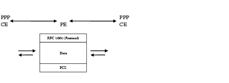
Some applications, such as transport of compressed voice between the two CEs, require a setup of an end-to-end PPP session between two CE routers that are connected to the same PE router. In such cases, HDLC pass-through mechanism is proposed and the interworking scenario is simplified to PPP transport for like-to-like services. PPP local switching functionality on the PE router provides simple HDLC connectivity between two end-users found on different CE routers as shown in Figure 20-1.
Figure 20-1 PPP Local Switching
The interfaces are HDLC encapsulated on the PE router. The CE routers may use PPP-based encapsulation.
Frames manipulated by the PE router preserve the PPP header as described in RFC-1661.
HDLC Like-to-Like Local Switching
Like PPP, HDLC sessions can be forwarded between two CE routers connected to the same PE router. The microcode implements a HDLC pass-through mechanism for the HDLC traffic. As the service provided is equivalent to a back-to-back serial connection between the two CE routers, the connection should be between same-speed interfaces with the matched Maximum Transmission Unit (MTU) configuration. There are no QoS requirements on the PE router since one interface cannot overrun another.
The interfaces are HDLC encapsulated on the PE router. CE routers may use any HDLC-based encapsulation, including Frame Relay.
Configuration Tasks and Examples
You can configure the L2VPN Local Switching - HDLC/PPP feature on a PE router using the following steps:
1.
2.
3.
4.
5.
6.
The following example shows you how to configure the L2VPN Local Switching - HDLC/PPP feature on the PE router:
config tinterface serial 3/0/20:0encapsulation hdlcinterface serial 4/0/11:9encapsulation hdlcconnect hdlcls serial3/0/20:0 serial4/0/11:9
Note
You can configure PPP on the CE router using the following steps:
1.
2.
3.
You can configure HDLC on the CE router using the following steps:
1.
2.
3.
Configuration Tasks for L2VPN
To configure L2VPN, you have to configure the following L2VPN features:
•
•
•
•
•
•
•
•
•
•
•
•
Setting Up the Pseudowire—AToM Circuit
The successful transmission of the Layer 2 frames between PE routers is due to the configuration of a connection called a pseudowire between the routers. You specify the following information on each PE router:
•
•
•
To set up a pseudowire connection or AToM circuit between two PE routers, enter the following commands beginning in global configuration mode:
Example 20-2 shows a sample configuration for the ATM AAL5 SDU over MPLS transport. The PVC on 0/100 is configured for AAL5 transport.
Example 20-2 ATM AAL5 SDU Support over MPLS
interface ATM4/0pvc 0/100 l2transportencapsulation aal5xconnect 13.13.13.13 100 encapsulation mplsConfiguring ATM AAL5 SDU Support over MPLS
ATM AAL5 SDU support over MPLS encapsulates ATM AAL5 service data units (SDUs) in MPLS packets and forwards them across the MPLS network. Each ATM AAL5 SDU is transported as one packet.
To configure ATM AAL5 SDU support over MPLS, enter the following commands beginning in global configuration mode:
Example 20-3 shows how to enable ATM AAL5 SDU support over MPLS on an ATM PVC.
Example 20-3 ATM AAL5 SDU Support over MPLS on an ATM PVC
interface atm1/0pvc 1/200 l2transportencapsulation aal5xconnect 13.13.13.13 100 encapsulation mplsVerifying ATM AAL5 SDU Support over MPLS
To verify that ATM AAL5 SDU support over MPLS is configured on a PVC, issue the show mpls l2transport vc command. Example 20-4 shows sample output for this command.
Example 20-4 show mpls l2transport vc Command Output
Router# show mpls l2transport vcLocal intf Local circuit Dest address VC ID Status--------- ------------- ------------ ----- ------ATM1/0 ATM AAL5 1/100 4.4.4.4 100 UPConfiguring ATM-to-ATM PVC Local Switching
The following ATM line cards are supported for Cisco 10000 series routers:
•
•
•
To configure ATM-to-ATM PVC local switching, enter the following commands, beginning in global configuration mode:
Example 20-5 shows how to enable ATM AAL5 SDU mode Layer 2 local switching.
Example 20-5 Enabling ATM AAL5 SDU Mode Layer 2 Local Switching
interface atm 1/0/0pvc 0/100 l2transportencapsulation aal5interface atm 2/0/0pvc 0/50 l2transportencapsulation aal5connect conn1 atm 1/0/0 0/100 atm 2/0/0 0/50Configuring OAM Cell Emulation for ATM AAL5 SDU Support over MPLS
If a PE router does not support the transport of Operation, Administration, and Maintenance (OAM) cells across an LSP, you can use OAM cell emulation to locally terminate or loop back the OAM cells. You configure OAM cell emulation on both PE routers, which emulates a VC by forming two unidirectional LSPs. You use the oam-ac emulation-enable and oam-pvc manage commands on both PE routers to enable OAM cell emulation.
After you enable OAM cell emulation on a router, you can configure and manage the ATM VC in the same manner as you would a terminated VC. A VC that is configured with OAM cell emulation can send loopback cells at configured intervals toward the local CE router.
The endpoint can be either of the following:
•
•
The OAM cells include the following:
•
•
These cells identify and report defects along a VC. When a physical link or interface failure occurs, intermediate nodes insert OAM AIS cells into all the downstream devices affected by the failure. When a router receives an AIS cell, it marks the ATM VC down and sends an RDI cell to let the remote end know about the failure.
Note
You can configure OAM cell emulation for ATM AAL5 SDU support over MPLS in the following ways:
•
•
Configuring OAM Cell Emulation for ATM AAL5 SDU Support over MPLS on PVCs
To configure OAM cell emulation for ATM AAL5 SDU support over MPLS on a PVC, enter the following commands beginning in global configuration mode:
Example 20-6 shows how to enable OAM cell emulation on an ATM PVC.
Example 20-6 OAM Cell Emulation on an ATM PVC
interface ATM 1/0/0pvc 1/200 l2transportencapsulation aal5xconnect 13.13.13.13 100 encapsulation mplsoam-ac emulation-enableoam-pvc manageExample 20-7 shows how to set the rate at which an AIS cell is sent to every 30 seconds.
Example 20-7 Setting the AIS Send Rate in OAM Cell Emulation on an ATM PVC
interface ATM 1/0/0pvc 1/200 l2transportencapsulation aal5xconnect 13.13.13.13 100 encapsulation mplsoam-ac emulation-enable 30oam-pvc manageVerifying OAM Cell Emulation on an ATM PVC
In Example 20-8, the show atm pvc command shows that OAM cell emulation is enabled on the ATM PVC.
Example 20-8 show atm pvc Command Output
Router# show atm pvc 5/500ATM4/1/0.200: VCD: 6, VPI: 5, VCI: 500UBR, PeakRate: 1AAL5-LLC/SNAP, etype:0x0, Flags: 0x34000C20, VCmode: 0x0OAM Cell Emulation: enabled, F5 End2end AIS Xmit frequency: 1 second(s)OAM frequency: 0 second(s), OAM retry frequency: 1 second(s)OAM up retry count: 3, OAM down retry count: 5OAM Loopback status: OAM DisabledOAM VC state: Not ManagedVerifiedILMI VC state: Not ManagedInPkts: 564, OutPkts: 560, InBytes: 19792, OutBytes: 19680InPRoc: 0, OutPRoc: 0InFast: 4, OutFast: 0, InAS: 560, OutAS: 560InPktDrops: 0, OutPktDrops: 0CrcErrors: 0, SarTimeOuts: 0, OverSizedSDUs: 0Out CLP=1 Pkts: 0OAM cells received: 26F5 InEndloop: 0, F5 InSegloop: 0, F5 InAIS: 0, F5 InRDI: 26OAM cells sent: 77F5 OutEndloop: 0, F5 OutSegloop: 0, F5 OutAIS: 77, F5 OutRDI: 0OAM cell drops: 0Status: UPConfiguring OAM Cell Emulation for ATM AAL5 SDU Support over MPLS in VC Class Configuration Mode
The following steps explain how to configure OAM cell emulation as part of a VC class. You can then apply the VC class to an interface, a subinterface, or a VC. When you configure OAM cell emulation in VC class configuration mode and then apply the VC class to an interface, the settings in the VC class apply to all the VCs on the interface, unless you specify a different OAM cell emulation value at a lower level, such as the subinterface or VC level.
For example, you can create a VC class that specifies OAM cell emulation and sets the rate of AIS cells to every 30 seconds. You can apply the VC class to an interface. Then, for one PVC, you can enable OAM cell emulation and set the rate of AIS cells to every 15 seconds. All the PVCs on the interface use the cell rate of 30 seconds, except for the one PVC that was set to 15 seconds.
To enable OAM cell emulation as part of a VC class and apply it to an interface, enter the following commands beginning in global configuration mode:
Example 20-9 configures OAM cell emulation for ATM AAL5 SDU support over MPLS in VC class configuration mode. The VC class is then applied to an interface.
Example 20-9 OAM Cell Emulation for ATM AAL5 SDU Support over MPLS in VC Class Configuration Mode—VC Class Applied to an Interface
vc-class atm oamclassencapsulation aal5oam-ac emulation-enable 30oam-pvc manageinterface atm1/0class-int oamclasspvc 1/200 l2transportxconnect 13.13.13.13 100 encapsulation mplsExample 20-10 shows how to configure OAM cell emulation for ATM AAL5 over MPLS in VC class configuration mode. The VC class is then applied to a PVC.
Example 20-10 OAM Cell Emulation for ATM AAL5 SDU Support over MPLS in VC Class Configuration Mode—VC Class Applied to a PVC
vc-class atm oamclassencapsulation aal5oam-ac emulation-enable 30oam-pvc manageinterface atm1/0pvc 1/200 l2transportclass-vc oamclassxconnect 13.13.13.13 100 encapsulation mplsExample 20-11 shows how to configure OAM cell emulation for ATM AAL5 over MPLS in VC class configuration mode. The VC class is then applied to an interface. One PVC is configured with OAM cell emulation at an AIS rate of 10. That PVC uses the AIS rate of 10 instead of 30.
Example 20-11 OAM Cell Emulation for ATM AAL5 SDU Support over MPLS in VC Class Configuration Mode—VC Class Applied to an Interface
vc-class atm oamclassencapsulation aal5oam-ac emulation-enable 30oam-pvc manageinterface atm1/0class-int oamclasspvc 1/200 l2transportoam-ac emulation-enable 10xconnect 13.13.13.13 100 encapsulation mplsConfiguring Ethernet over MPLS
Ethernet over MPLS works by encapsulating Ethernet protocol data units (PDUs) in MPLS packets and forwarding them across the MPLS network. Each PDU is transported as a single packet. Several methods exists for configuring Ethernet over MPLS:
•
•
•
You can configure Ethernet over MPLS in the following ways:
•
•
•
Ethernet over MPLS Restrictions
The following restrictions pertain to the Ethernet over MPLS transport:
•
•
•
•
Configuring Ethernet over MPLS in VLAN Mode
A virtual LAN (VLAN) is a switched network that is logically segmented by functions, project teams, or applications regardless of the physical location of users. Ethernet over MPLS allows you to connect two VLAN networks that are in different locations. You configure the PE routers at each end of the MPLS backbone and add a point-to-point virtual circuit (VC). Only the two PE routers at the ingress and egress points of the MPLS backbone know about the VCs dedicated to transporting Layer 2 VLAN traffic. All other routers do not have table entries for those VCs.
For Ethernet over MPLS in VLAN mode, it is possible for VPN circuits to coexist with pseudowire circuits. Because the port is in promiscuous mode, the frames are filtered by the VLAN ID.
Note
To configure Ethernet over MPLS in VLAN mode, enter the following commands beginning in global configuration mode:
Configuring Ethernet over MPLS in Port Mode
Port mode allows a frame coming into an interface to be packed into an MPLS packet and transported over the MPLS backbone to an egress interface. The entire Ethernet frame without the preamble or FCS is transported as one packet. To configure port mode, use the xconnect command in main interface mode and specify the destination address and the VC ID. The syntax and semantics of the xconnect command are the same as for all other transport types. Each interface is associated with one unique pseudowire VC label.
When configuring Ethernet over MPLS in port mode, use the following guidelines:
•
•
To configure Ethernet over MPLS in port mode, enter the following commands beginning in global configuration mode:
Example 20-12 shows how to configure VC 123 in Ethernet port mode:
Example 20-12 Ethernet over MPLS in Port Mode
pseudowire-class ethernet-portencapsulation mplsinterface gigabitethernet1/0xconnect 10.0.0.1 123 pw-class ethernet-port
Note
Verifying Ethernet over MPLS in VLAN Mode and Port Mode
To determine if a VC is set up in VLAN mode or port mode, issue the show mpls l2transport vc command.
Example 20-13 shows two VCs set up for Ethernet over MPLS:
•
•
Example 20-13 show mpls l2transport vc Command Output
Router# show mpls l2transport vcLocal intf Local circuit Dest address VC ID Status------------- -------------------- --------------- ---------- ----------Gi4/0.1 Eth VLAN 2 11.1.1.1 2 UPGi8/0/1 Ethernet 11.1.1.1 8 UPIf you issue the show mpls l2transport vc detail command, the output is similar, as shown in Example 20-14.
Example 20-14 show mpls l2transport vc detail Command Output
Router# show mpls l2transport vc detailLocal interface: Gi4/0.1 up, line protocol up, Eth VLAN 2 upDestination address: 11.1.1.1, VC ID: 2, VC status: up...Local interface: Gi8/0/1 up, line protocol up, Ethernet upDestination address: 11.1.1.1, VC ID: 8, VC status: upIEEE 802.1Q Tunneling for AToM—QinQ
The IEEE 802.1Q Tunneling (QinQ) for AToM feature is described in the following topics:
•
•
Prerequisites for IEEE 802.1Q Tunneling (QinQ) for AToM
In Cisco IOS software Release 12.2(33)SB, the QinQ (short for 802.1Q-in-802.1Q) tunneling and tag rewrite feature is supported on the following Cisco 10000 series engines and line cards:
•
•
•
•
•
Restrictions for IEEE 802.1Q Tunneling (QinQ) for AToM
In Cisco IOS Release 12.2(33)SB, the QinQ tunneling and tag rewrite feature has the following restrictions:
•
•
Ethernet VLAN Q-in-Q AToM
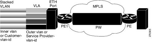
In Metro Ethernet deployment, in which CE routers and PE routers are connected through an Ethernet switched access network, packets that arrive at PE routers can contain up to two IEEE 802.1q VLAN tags (one inner VLAN tag which identifies the customer; and another outer VLAN tag which denotes the customer's service provider). This technique of allowing multiple VLAN tagging on the same Ethernet packet and creating a stack of VLAN IDs is known as QinQ (short for 802.1Q-in-802.1Q). Figure 20-2 shows how different edge devices can do L2 switching on the different levels of the VLAN stack.
Figure 20-2 Ethernet VLAN QinQ
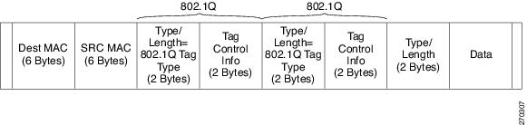
When the outer VLAN tag is the service-delimiting VLAN tag, QinQ packets are processed similar to the ones with one VLAN tag (case previously named Ethernet VLAN Q-in-Q modified, which is already supported in the 12.2(31) SB release). However, when a customer must use a combination of the outer and inner VLAN tags to delimit service for customers, the edge device should be able to choose a unique pseudowire based on a combination of the inner and outer VLAN IDs on the packet shown in Figure 20-3. The customer may want to be able to rewrite both the inner and the outer VLAN IDs on the traffic egress side.
Figure 20-3 Ethernet VLAN QinQ Header
The IEEE 802.1Q Tunneling (QinQ) for AToM can be further explained as follows:
•
•
QinQ Tunneling Based on Inner and Outer VLAN Tags
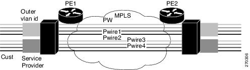
When handling incoming QinQ Ethernet traffic, the Cisco 10000 series edge router allows a customer to choose a unique pseudowire endpoint to switch the traffic based on the combination of inner and outer VLAN IDs. For example, Figure 20-4 shows how a unique pseudowire is selected depending upon the combination of inner (customer edge) and outer (service provider) VLAN IDs. Thus, traffic for different customers can be kept separate.
Figure 20-4 QinQ Connection
Rewriting Inner and Outer VLAN Tags on QinQ Frames
When managing incoming AToM Ethernet QinQ traffic, the Cisco 10000 edge router:
1.
2.
Support for these features is added in Cisco IOS Release 12.2(33). The QinQ AToM feature is a like-to-like interworking case over AToM. This feature requires changes to the microcode to allow it to overwrite two layers of VLAN tags on Ethernet QinQ traffic, transported across AToM pseudowires.
•
•
Only Unambiguous VLAN tagged Ethernet QinQ interfaces are supported in this release. The Ethernet VLAN Q-in-Q rewrite of both VLAN Tags capability is supported only on Ethernet sub-interfaces with a QinQ encapsulation and explicit pair of VLAN IDs defined.
Configuration Examples
Example 20-15 shows an unambiguous QinQ configured on GigE subinterface.
Example 20-15 Unambiguous QinQ
interface GigabitEthernet1/0/0.100encapsulation dot1q 100 second-dot1q 200xconnect 23.0.0.16 410 encapsulation mplsExample 20-16 shows an ambiguous QinQ configured on a GigE subinterface.
Example 20-16 Ambiguous QinQ
interface GigabitEthernet1/0/0.200encapsulation dot1q 200 second-dot1q 1000-2000,3000,3500-4000xconnect 23.0.0.16 420 encapsulation mplsinterface GigabitEthernet1/0/0.201encapsulation dot1q 201 second-dot1q anyxconnect 23.0.0.16 430 encapsulation mpls
Note
Verifying QinQ AToM
Example 20-17 shows the command output of the show mpls l2transport vc command, which is used to verify the VC set up in EoMPLS QinQ mode.
Example 20-17 show mpls l2transport vc Command Output
Local intf Local circuit Dest address VC ID Status------------- -------------------------- --------------- ---------- ----------Gi1/0/0.1 Eth VLAN:100/200 100.1.1.2 1 UPRemote Ethernet Port Shutdown
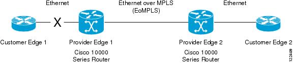
This Cisco IOS feature allows a service provider edge (PE) router on the local end of an Ethernet over MPLS (EoMPLS) pseudowire to detect a remote link failure and shutdown of the Ethernet port on the local customer edge (CE) router. Because the Ethernet port on the local CE router is shut down, the router does not lose data by continuously sending traffic to the failed remote link. This is beneficial if the link is configured as a static IP route.
Figure 20-5 illustrates a condition in an EoMPLS wide area network (WAN) with a down Layer 2 tunnel link between a CE1 router and the PE1 router. A CE2 router on the far side of the Layer 2 tunnel, continues to forward traffic to CE1 through the L2 tunnel.
Figure 20-5 Remote Link Outage in EoMPLS Wide Area Network
In earlier releases than Cisco IOS Release 12.2(33)SB, the PE2 router did not detect a failed remote link. Traffic forwarded from CE2 to CE1 is lost until routing or spanning tree protocols detected the down remote link. If the link was configured with static routing, remote link outage can be difficult to detect by the L3 routing protocol.
With Any Transport over MPLS (AToM): Remote Ethernet Port Shutdown, the PE2 router detects the remote link failure and causes a shutdown of the local CE2 Ethernet port. When the remote L2 tunnel link is restored, the local interface is automatically restored as well. The possibility of data loss is thus diminished.
With reference to Figure 20-5, a remote Ethernet shutdown sequence occurs as follows:
1.
2.
3.
4.
5.
6.
Restrictions for Configuring Remote Ethernet Port Shutdown
The following restrictions pertain to the Remote Ethernet Port Shutdown feature:
•
•
Configuring Remote Ethernet Port Shutdown
By default, the Any Transport over MPLS (AToM): Remote Ethernet Port Shutdown feature is automatically enabled when an image with this feature supported is loaded on the Cisco 10000 series router. However, to enable the Remote Ethernet Port Shutdown feature, enter the remote link failure notification command, as shown in Example 20-18.
To disable the feature, enter the no remote link failure notification command (Example 20-19).
Example 20-18 Enabling Remote Ethernet Port Shutdown under the Xconnect Configuration
pseudowire-class eomplsencapsulation mpls!interface GigabitEthernet1/0/0xconnect 1.1.1.1 1 pw-class eomplsremote link failure notification!Example 20-19 Disabling Remote Ethernet Port Shutdown under the Xconnect Configuration
pseudowire-class eomplsencapsulation mpls!interface GigabitEthernet1/0/0xconnect 1.1.1.1 1 pw-class eomplsno remote link failure notification!To see the operational status of all remote L2 tunnels by interface, enter show interface and show ip interface brief commands, as shown in Example 20-20.
Example 20-20 Operational Status for All Remote L2 Tunnels by Interface
router# show interface GigabitEthernet1/0/0GigabitEthernet1/0/0 is L2 Tunnel remote down, line protocol is upHardware is Half-height Gigabit Ethernet MAC Controller, address is 0009.b68f.9b18 (bia 0009.b68f.9b18)MTU 1500 bytes, BW 1000000 Kbit, DLY 10 usec,............router# sh ip interface briefInterface IP-Address OK? Method Status ProtocolFastEthernet0/0/0 24.3.8.1 YES NVRAM up upGigabitEthernet1/0/0 unassigned YES NVRAM L2 Tunnel remote down upGigabitEthernet2/0/0 30.1.1.1 YES manual up upEnter show controller and show controller interface commands to see the port transceiver state, as shown in Example 20-21.
Example 20-21 Port Transceiver State
router# show controller GigabitEthernet1/0/0Interface GigabitEthernet1/0/0(idb 0x4FB5CA7C)Hardware is Half-height Gigabit Ethernet MAC Controller, network connection mode is autonetwork link is L2 Tunnel remote downloopback type is none......Configuring Ethernet over MPLS with VLAN ID Rewrite
The VLAN ID Rewrite feature enables you to use VLAN interfaces with different VLAN IDs at both ends of the tunnel. The Cisco 10000 series router automatically performs VLAN ID Rewrite on the disposition PE router. There is no configuration required.
Configuring Frame Relay over MPLS
Frame Relay over MPLS encapsulates Frame Relay protocol data units (PDUs) in MPLS packets and forwards them across the MPLS network. For Frame Relay, you can set up data-link connection identifier (DLCI)-to-DLCI connections or port-to-port connections.
•
•
Note
You can configure Frame Relay over MPLS in the following ways:
•
•
•
Configuring Frame Relay over MPLS with DLCI-to-DLCI Connections
To configure Frame Relay over MPLS with DLCI-to-DLCI connections, enter the following commands beginning in global configuration mode:
Example 20-22 shows how to enable Frame Relay over MPLS with DLCI-to-DLCI connections.
Example 20-22 Frame Relay over MPSL with DLCI-to-DLCI Connections
frame-relay switchinginterface Serial3/1encapsulation frame-relay ietfframe-relay intf-type dceexitconnect fr1 Serial 5/0 1000 l2transportxconnect 10.0.0.1 123 encapsulation mplsConfiguring Frame Relay over MPLS with Port-to-Port Connections
When you set up a port-to-port connection between PE routers, you use HDLC mode to transport the Frame Relay encapsulated packets. Perform this task to set up Frame Relay port-to-port connections.
To configure Frame Relay over MPLS with port-to-port connections, enter the following commands beginning in global configuration mode:
Example 20-23 shows how to enable Frame Relay over MPLS with port-to-port connections.
Example 20-23 Frame Relay over MPLS With Port-to-Port Connections
interface serial5/0
encapsulation hdlc
xconnect 10.0.0.1 123 encapsulation mpls
Enabling Other PE Devices to Transport Frame Relay Packets
You can configure an interface as a data terminal equipment (DTE) device or a data circuit-terminating equipment (DCE) switch, or as a switch connected to a switch with network-to-network interface (NNI) connections. Use the following command in interface configuration mode:
frame-relay intf-type [dce | dte | nni]
The following table explains the keywords:
Local Management Interface and Frame Relay over MPLS
Local Management Interface (LMI) is a protocol that communicates status information about permanent virtual circuits (PVCs). When a PVC is added, deleted, or changed, the LMI notifies the endpoint of the status change. LMI also provides a polling mechanism that verifies that a link is up.
LMI Process
To determine the PVC status, LMI checks that a PVC is available from the reporting device to the Frame Relay end-user device. If a PVC is available, LMI reports that the status is "Active," which means that all interfaces, line protocols, and core segments are operational between the reporting device and the Frame Relay end-user device. If any of those components is not available, the LMI reports a status of "Inactive."
Note
Figure 20-6 is a sample topology that illustrates how LMI works.
Figure 20-6 Sample LMI Topology
In Figure 20-6, note the following:
•
•
•
•
The LMI protocol behavior depends on DLCI-to-DLCI connections versus port-to-port connections.
DLCI-to-DLCI Connections
If DLCI-to-DLCI connections are configured, LMI runs locally on the Frame Relay ports between the PE and CE devices.
•
•
–
–
–
For DTE/DCE configurations, the following LMI behavior exists:
The Frame Relay device accessing the network (DTE) does not report PVC status. Only the network device (DCE) or NNI can report status. Therefore, if a problem exists on the DTE side, the DCE is not aware of the problem.
Port-to-Port Connections
If port-to-port connections are configured, the PE routers do not participate in the LMI status-checking procedures. LMI operates between the CE routers only. The CE routers must be configured as DCE-DTE or NNI-NNI.
For information about LMI, including configuration instructions, see the "Configuring the LMI" section of the Configuring Frame Relay document.
Configuring Frame Relay-to-Frame Relay Local Switching
Frame Relay switching is a means of switching packets based upon the data link connection identifier (DLCI), which can be looked upon as the Frame Relay equivalent of a MAC address. You perform the switching by configuring your router or access server as a Frame Relay network. There are two parts to a Frame Relay network: the Frame Relay data terminal equipment (DTE) (the router or access server) and the Frame Relay data communications equipment (DCE) switch.
Local switching allows you to switch Layer 2 data between two interfaces of the same type for example, ATM-to-ATM, or Frame-Relay-to-Frame-Relay.
For background information about Frame-Relay-to-Frame-Relay Local Switching, see the Distributed Frame Relay Switching feature guide.
You can switch between virtual circuits on the same port, as detailed in the "Configuring Frame Relay Same-Port Switching" section.
The following channelized line cards are supported for the Cisco 10000 series routers:
•
•
•
•
The following packet over SONET line cards are supported for the Cisco 10000 series routers:
•
•
•
The Frame Relay-to-Frame Relay Local Switching feature is described in the following topics:
•
•
•
Configuring Frame Relay for Local Switching
To configure Frame Relay for local switching, enter the following commands, beginning in global configuration mode.
Example 20-24 configures Frame-Relay-to-Frame-Relay for local switching.
Example 20-24 Configuring Frame Relay-to-Frame Relay for Local Switching
frame-relay switchinginterface serial 1/0/0.1/1:0encapsulation frame-relayframe-relay interface-dlci 100 switchedexitconnect connection1 serial1/0/0.1/1:0 100 serial2/0/0.1/2:0 101Configuring Frame Relay Same-Port Switching
Use the following steps to configure local Frame Relay same-port switching on a single interface, beginning in global configuration mode.
Example 20-25 shows how to configure Frame Relay same-port switching.
Example 20-25 Configuring Frame Relay Same-Port Switching
frame-relay switchinginterface serial 1/0/0.1/1:0encapsulation frame-relayframe-relay intf-type nniframe-relay interface-dlci 100 switchedexitexitconnect connection1 serial1/0 100 serial1/0 200Verifying Layer 2 Local Switching for Frame Relay
To verify configuration of the Layer 2 Local Switching feature, use the show connection frame-relay-to-frame-relay command and the show frame-relay pvc command in privileged EXEC mode.
Example 20-26 shows the output of the show connection frame-relay-to-frame-relay command, which displays the local connection between a Frame Relay interface and a Frame Relay local switching interface.
Example 20-26 show connection frame-relay-to-frame-relay Command Output
Router# show connection frame-relay-to-frame-relayID Name Segment 1 Segment 2 State==================================================================1 fr2fr Se3/0/0.1/1:0 100 Se3/0/0.1/2:0 200 UPExample 20-27 shows the output of the show frame-relay pvc command, which shows a switched Frame Relay PVC.
Example 20-27 show frame-relay pvc Command Output
Router# show frame-relay pvc 16PVC Statistics for interface POS5/0 (Frame Relay NNI)DLCI = 16, DLCI USAGE = SWITCHED, PVC STATUS = UP, INTERFACE = POS5/0LOCAL PVC STATUS = UP, NNI PVC STATUS = ACTIVEinput pkts 0 output pkts 0 in bytes 0out bytes 0 dropped pkts 100 in FECN pkts 0in BECN pkts 0 out FECN pkts 0 out BECN pkts 0in DE pkts 0 out DE pkts 0out bcast pkts 0 out bcast bytes 0switched pkts 0Detailed packet drop counters:no out intf 0 out intf down 100 no out PVC 0in PVC down 0 out PVC down 0 pkt too big 0pvc create time 00:25:32, last time pvc status changed 00:06:31Configuring QoS Features
For information about configuring QoS features on the Cisco 10000 series router, see the Cisco 10000 Series Router Quality of Service Configuration Guide.
Table 20-4 and Table 20-5 outline the level of support for modular QoS CLI (MQC) commands as they relate to Frame Relay DLCI interfaces.
The values shown in the tables are as follows:
•
•
•
Configuring HDLC and PPP over MPLS
With HDLC over MPLS, the entire HDLC packet is transported. The ingress PE router removes only the HDLC flags and frame check sequence (FCS) bits. The contents of the packet are not used or changed.
With PPP over MPLS, the ingress PE router removes the flags, address, control field, and the FCS.
HDLC over MPLS is described in:
•
•
•
Restrictions for HDLC over MPLS
The following restrictions pertain to the HDLC over MPLS feature:
•
•
Restrictions for PPP over MPLS
The following restrictions pertain to the PPP over MPLS feature:
•
•
•
Configuring HDLC over MPLS or PPP over MPLS
To configure HDLC over MPLS or PPP over MPLS, enter the following commands beginning in global configuration mode:
Estimating the Size of Packets Traveling Through the Core Network
The following calculation helps you determine the size of the packets traveling through the core network. You set the maximum transmission unit (MTU) on the core-facing interfaces of the P and PE routers to accommodate packets of this size.
The MTU should be greater than or equal to the total bytes of the items in the following equation:
Core MTU >= (Edge MTU + Transport header + AToM header + (MPLS label stack size* MPLS
label size))
The following sections describe the variables used in the equation.
Edge MTU
The edge MTU is the MTU for the customer-facing interfaces.
Transport Header
The transport header depends on the transport type. Table 20-6 lists the specific sizes of the headers.
AToM Header
The AToM header is 4 bytes (control word). The Cisco 10000 series router adds the control word for all supported transport types by default.
MPLS Label Stack
The MPLS label stack size depends on the configuration of the core MPLS network.
•
•
•
•
•
•
•
Other circumstances can increase the MPLS label stack size. Therefore, analyze the complete data path between the AToM tunnel endpoints and determine the maximum MPLS label stack size for your network. Then multiply the label stack size by the size of the MPLS label.
Estimating Packet Size—Example
Example 20-28 shows how to estimate the size of packets. The example uses the following assumptions:
•
•
•
•
Example 20-28 Estimating the MTU for Packets
Core MTU >= (Edge MTU + Transport header + AToM header + (MPLS label stack size* MPLS
label size))
1500 + 18 + 0 + (2 * 4 ) = 1526You must configure the P and PE routers in the core to accept packets of 1526 bytes. See the following section for setting the MTU size on the P and PE routers.
Changing the MTU Size on P and PE Routers
After you determine the MTU size to set on your P and PE routers, you can issue the mtu command on the routers to set the MTU size. The following example specifies an MTU size of 1526 bytes.
Router(config-if)# mtu 1526Setting Experimental Bits with AToM
MPLS AToM uses the three experimental (EXP) bits in a label to determine the queue of packets.The EXP bits are set to 0 (zero) by default. Table 20-7 summarizes the commands you can use to override the default values.
Set the experimental bits in both the VC label and the LSP tunnel label. You set the experimental bits in the VC label, because the LSP tunnel label might be removed at the penultimate router.
To set the experimental bits, enter the following commands beginning in global configuration mode:
Displaying the Traffic Policy Assigned to an Interface
To display the traffic policy attached to an interface, use the show policy-map interface command.
Example 20-29 uses the set mpls experimental command with the match any command under a default class. This means that every packet tunneled onto a particular AToM VC carries the same MPLS experimental bit value.
Example 20-29 Setting EXP Bits Using the match any Command
class-map match-any default-classmatch anypolicy-map atm-default-policyclass default-classset mpls experimental 3!!interface atm4/0service-policy input atm-default-policyExample 20-30 uses the set mpls experimental command with the match cos command. This allows packets tunneled onto a particular AToM VC to carry different MPLS experimental bit values. The match cos command is only configurable on Ethernet VLAN subinterfaces.
Example 20-30 Setting EXP Bits Using the match cos Command
class-map match-any match_cos_lowmatch cos 0 1 2 3class-map match-any match_cos_highmatch cos 4 5 6 7policy-map ether-clp-policyclass match_cos_lowset mpls experimental 1class match_cos_highset mpls experimental 5!!interface Gi0/0.1service-policy input ether-clp-policyConfiguring QoS Features
For information about configuring QoS features on the Cisco 10000 series router, see the Cisco 10000 Series Router Quality of Service Configuration Guide.
Table 20-8 and Table 20-9 describe the policy map actions supported on various interfaces. The tables indicate the following:
•
•
•
Table 20-10 and Table 20-11 describe support for class map match criteria on various interfaces. Table 20-10 describes match criteria support for inbound traffic and Table 20-11 describes support for outbound traffic.
Monitoring and Maintaining L2VPN
To monitor and maintain the configuration of L2VPN features, use the following commands in privileged EXEC mode. Note that with the exception of the show mpls l2transport command, these commands can produce output that is meant to be used by Cisco Systems technical support personnel only.
Caution
Configuration Example—Frame Relay over MPLS
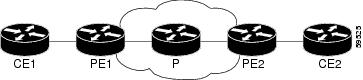
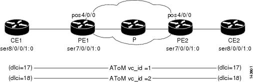
Example 20-31 shows the configuration of Frame Relay over MPLS on two provider edge routers, PE1 and PE2, and on two customer edge routers, CE1 and CE2. The topology for the example is shown in Figure 20-7.
Figure 20-7 Frame Relay over MPLS Example Topology
For the AToM VCs to come up, MPLS/LDP and a routing protocol need to be run in the core network (PE1---P----PE2). PE1 and PE2 show that they are enabled with the OSPF routing protocol and MPLS/LDP.
Example 20-31 Frame Relay over MPLS Configuration
CE1 Configuration for Frame Relay
================================interface Serial8/0/0.1/1:0no ip addressencapsulation frame-relayno fair-queueframe-relay lmi-type q933aframe-relay intf-type dceinterface Serial8/0/0.1/1:0.1 point-to-pointip address 192.1.1.1 255.255.255.0frame-relay interface-dlci 17!interface Serial8/0/0.1/1:0.2 point-to-pointip address 192.1.2.1 255.255.255.0frame-relay interface-dlci 18PE1 Configuration for LDP and AToM VC
==================================!Enabling LDPmpls ldp graceful-restart timers neighbor-liveness 300mpls ldp graceful-restart timers max-recovery 600mpls ldp graceful-restartmpls ldp router-id Loopback0 forcempls label protocol ldp!Define Loopback address for LDP protocolinterface Loopback0ip address 1.1.1.1 255.255.255.255!Enable MPLS/LDP on the core interfaceinterface POS4/0/0ip address 50.0.0.1 255.0.0.0mpls label protocol ldpmpls ipcrc 32clock source internal!!Enabling OSPF protocolrouter ospf 100log-adjacency-changesnetwork 1.0.0.0 0.255.255.255 area 100network 50.0.0.0 0.255.255.255 area 100!Define pseudowire-classpseudowire-class pw_atom1encapsulation mpls!FR configuration with two subinterfacesinterface Serial8/0/0.1/1:0no ip addressencapsulation frame-relayno fair-queueframe-relay lmi-type q933a!interface Serial8/0/0.1/1:0.1 point-to-point!interface Serial8/0/0.1/1:0.2 point-to-point!!Two AToM VC configuration with vc ids 1 & 2, 2.2.2.2 is LB addr of PE2connect atom1 Serial8/0/0.1/1:0 17 l2transportxconnect 2.2.2.2 1 pw-class pw_atom1!!connect atom2 Serial8/0/0.1/1:0 18 l2transportxconnect 2.2.2.2 2 pw-class pw_atom1PE2 Configuration
================================!Enabling LDPmpls ldp graceful-restart timers neighbor-liveness 300mpls ldp graceful-restart timers max-recovery 600mpls ldp graceful-restartmpls ldp router-id Loopback0 forcempls label protocol ldp!Define Loopback address for LDP protocolinterface Loopback0ip address 2.2.2.2 255.255.255.255!Enable MPLS/LDP on the core interfaceinterface POS4/0/0ip address 60.0.0.2 255.0.0.0mpls label protocol ldpmpls ipcrc 32clock source internal!!Enabling OSPF protocolrouter ospf 100log-adjacency-changesnetwork 2.0.0.0 0.255.255.255 area 100network 60.0.0.0 0.255.255.255 area 100!Define pseudowire-classpseudowire-class pw_atom1encapsulation mpls!FR configuration with two subinterfacesinterface Serial8/0/0.1/1:0no ip addressencapsulation frame-relayno fair-queueframe-relay lmi-type q933ainterface Serial8/0/0.1/1:0.1 point-to-pointinterface Serial8/0/0.1/1:0.2 point-to-point!Two AToM VC configuration with vc ids 1 & 2connect atom1 Serial8/0/0.1/1:0 17 l2transportxconnect 1.1.1.1 1 pw-class pw_atom1!!connect atom2 Serial8/0/0.1/1:0 18 l2transportxconnect 1.1.1.1 2 pw-class pw_atom1CE2 Configuration
================================interface Serial8/0/0.1/1:0no ip addressencapsulation frame-relayno fair-queueframe-relay lmi-type q933aframe-relay intf-type dce!interface Serial8/0/0.1/1:0.1 point-to-pointip address 192.1.1.2 255.255.255.0frame-relay interface-dlci 17!interface Serial8/0/0.1/1:0.2 point-to-pointip address 192.1.2.2 255.255.255.0frame-relay interface-dlci 18Verifying PE1 Configuration
The PE1 router shows two AToM VCs are up.
================================router# show mpls l2tran vcLocal intf Local circuit Dest address VC ID Status------------- -------------------------- --------------- ---------- ----------Se8/0/0.1/1:0 FR DLCI 17 2.2.2.2 1 UPSe8/0/0.1/1:0 FR DLCI 18 2.2.2.2 2 UProuter# show mpls l2tran vc 1 detLocal interface: Se8/0/0.1/1:0 up, line protocol up, FR DLCI 17 upDestination address: 2.2.2.2, VC ID: 1, VC status: upOutput interface: PO4/0/0, imposed label stack {93 19}Preferred path: not configuredDefault path: activeNext hop: point2pointCreate time: 00:00:49, last status change time: 00:00:06Signaling protocol: LDP, peer 2.2.2.2:0 upMPLS VC labels: local 19, remote 93Group ID: local 0, remote 0MTU: local 1500, remote 1500Remote interface description:Sequencing: receive disabled, send disabledVC statistics:packet totals: receive 0, send 0byte totals: receive 0, send 0packet drops: receive 0, seq error 0, send 0router# sh mpls l2tran vc 2 detLocal interface: Se8/0/0.1/1:0 up, line protocol up, FR DLCI 18 upDestination address: 2.2.2.2, VC ID: 2, VC status: upOutput interface: PO4/0/0, imposed label stack {98 19}Preferred path: not configuredDefault path: activeNext hop: point2pointCreate time: 00:00:53, last status change time: 00:00:10Signaling protocol: LDP, peer 2.2.2.2:0 upMPLS VC labels: local 22, remote 98Group ID: local 0, remote 0MTU: local 1500, remote 1500Remote interface description:Sequencing: receive disabled, send disabledVC statistics:packet totals: receive 0, send 0byte totals: receive 0, send 0packet drops: receive 0, seq error 0, send 0Any Transport over MPLS—Tunnel Selection
Tunnel Selection allows you to specify the path that Any Transport over MPLS (AToM) traffic uses. You can specify either a MPLS traffic engineering tunnel or a destination IP address. If the specified path is unreachable, you can specify that the virtual circuits (VCs) should use the default path, which is the path that MPLS Label Distribution Protocol (LDP) uses for signaling.
Note
See the Any Transport over MPLS: Tunnel Selection document for the following information:
•
•
•
•
•
•
Configuration Example—Any Transport over MPLS: Tunnel Selection
The following example sets up two preferred paths for PE1. One preferred path specifies an MPLS traffic engineering tunnel. The other preferred path specifies an IP address of a loopback address on PE2. There is a static route configured on PE1 that uses a TE tunnel to reach the IP address on PE2.
Router PE1
mpls label protocol ldpmpls traffic-eng tunnelsmpls ldp router-id Loopback0pseudowire-class pw1encapsulation mplspreferred-path interface Tunnel1 disable-fallback!pseudowire-class pw2encapsulation mplspreferred-path peer 10.18.18.18!interface Loopback0ip address 10.2.2.2 255.255.255.255no ip directed-broadcastno ip mroute-cache!interface Tunnel1ip unnumbered Loopback0no ip directed-broadcasttunnel destination 10.16.16.16tunnel mode mpls traffic-engtunnel mpls traffic-eng priority 7 7tunnel mpls traffic-eng bandwidth 1500tunnel mpls traffic-eng path-option 1 explicit name path-tu1!interface Tunnel2ip unnumbered Loopback0no ip directed-broadcasttunnel destination 10.16.16.16tunnel mode mpls traffic-engtunnel mpls traffic-eng priority 7 7tunnel mpls traffic-eng bandwidth 1500tunnel mpls traffic-eng path-option 1 dynamic!interface gigabitethernet0/0/0no ip addressno ip directed-broadcastno negotiation auto!interface gigabitethernet0/0/0.1encapsulation dot1Q 222no ip directed-broadcastxconnect 10.16.16.16 101 pw-class pw1!interface ATM1/0/0no ip addressno ip directed-broadcastno atm enable-ilmi-trapno atm ilmi-keepalivepvc 0/50 l2transportencapsulation aal5xconnect 10.16.16.16 150 pw-class pw2!interface gigabitEthernet2/0/1ip address 10.0.0.1 255.255.255.0no ip directed-broadcasttag-switching ipmpls traffic-eng tunnelsip rsvp bandwidth 15000 15000!router ospf 1log-adjacency-changesnetwork 10.0.0.0 0.0.0.255 area 0network 10.2.2.2 0.0.0.0 area 0mpls traffic-eng router-id Loopback0mpls traffic-eng area 0!ip route 10.18.18.18 255.255.255.255 Tunnel2!ip explicit-path name path-tu1 enablenext-address 10.0.0.1index 3 next-address 10.0.0.1Router PE2
mpls label protocol ldpmpls traffic-eng tunnelsmpls ldp router-id Loopback0interface Loopback0ip address 10.16.16.16 255.255.255.255no ip directed-broadcastno ip mroute-cache!interface Loopback2ip address 10.18.18.18 255.255.255.255no ip directed-broadcast!interface gigabitEthernet3/1ip address 10.0.0.2 255.255.255.0no ip directed-broadcastmpls traffic-eng tunnelsmpls ipno cdp enableip rsvp bandwidth 15000 15000!interface gigabitEthernet3/3no ip addressno ip directed-broadcastno cdp enable!interface gigabitEthernet3/3.1encapsulation dot1Q 222no ip directed-broadcastno cdp enablempls l2transport route 10.2.2.2 101!interface ATM5/0no ip addressno ip directed-broadcastno atm enable-ilmi-trapno atm ilmi-keepalivepvc 0/50 l2transportencapsulation aal5xconnect 10.2.2.2 150 encapsulation mpls!router ospf 1log-adjacency-changesnetwork 10.0.0.0 0.0.0.255 area 0network 10.16.16.16 0.0.0.0 area 0mpls traffic-eng router-id Loopback0mpls traffic-eng area 0