-
Cisco 10000 Series Router Software Configuration Guide
-
About This Guide
-
Broadband Aggregation and Leased-Line Overview
-
Scalability and Performance
-
Configuring Remote Access to MPLS VPN
-
Configuring Multiprotocol Label Switching
-
Configuring the Layer 2 Tunnel Protocol Access Concentrator and Network Server
-
Configuring PPPoE over Ethernet and IEEE 802.1Q VLAN
-
Configuring IP Unnumbered on IEEE 802.1Q VLANs
-
Configuring ATM Permanent Virtual Circuit Autoprovisioning
-
Configuring the Multihop Feature
-
Configuring Address Pools
-
Configuring Local AAA Server, User Database--Domain to VRF
-
Configuring Traffic Filtering
-
Unicast Reverse Path Forwarding
-
Configuring Automatic Protection Switching
-
Configuring IP Multicast
-
Configuring RADIUS Features
-
Cisco 10000 Series Router PXF Stall Monitor
-
SSO - BFD
-
Configuring Link Noise Monitoring
-
Configuring L2 Virtual Private Networks
-
Configuring L2VPN Interworking
-
Configuring Multilink Point-to-Point Protocol Connections
-
Configuring Gigabit EtherChannel Features
-
Configuring IP Version 6
-
Configuring Template ACLs
-
Protecting the Router from DoS Attacks
-
IP Tunneling
-
RADIUS Attributes
-
Glossary
-
 Feedback
Table Of Contents
Configuring the Layer 2 Tunnel Protocol Access Concentrator and Network Server
Feature History for IP Reassembly
Required Configuration Tasks for LAC
Enabling the LAC to Look for Tunnel Definitions
Optional Configuration Tasks for LAC
Enabling Sessions with Different Domains to Share the Same Tunnel
Enabling the LAC to Conduct Tunnel Service Authorization
Configuring Sessions Per Tunnel Limiting on the LAC
RADIUS Server Optional Configuration Tasks for LAC
Enabling Tunnel Sharing for RADIUS Services
Enabling the RADIUS Server to Conduct Tunnel Service Authorization
Configuring Sessions Per Tunnel Limiting in the RADIUS Service Profile
Monitoring and Maintaining LAC
Virtual Routing and Forwarding Instance
Required Configuration Tasks for LNS
Configuring the Virtual Template Interface
Configuring the LNS to Initiate and Receive L2TP Traffic
Optional Configuration Tasks for LNS
Configuring per VRF AAA Services
Configuring Sessions per Tunnel Limiting on the LNS
Configuring RADIUS Attribute Accept or Reject Lists
Configuring the LNS for RADIUS Tunnel Accounting
Configuring the LNS for RADIUS Tunnel Authentication
Configuration Examples for LNS
Managed LNS Configuration Example
Tunnel Accounting Configuration Examples
Tunnel Authentication Configuration Examples
Monitoring and Maintaining LNS
Configuring the Layer 2 Tunnel Protocol Access Concentrator and Network Server
The Cisco 10000 series router supports the Layer 2 Tunnel Protocol (L2TP) to allow users and telecommuters to connect to their corporate intranets or extranets. The Cisco 10000 series router supports the Layer 2 access concentrator (LAC) and Managed L2TP network server features. These features enable the Cisco 10000 series router to act as either a LAC or an LNS device.
Acting as the LAC, the Cisco 10000 router uses L2TP tunnels to forward packets to the LNS. As the LNS, the Cisco 10000 series router terminates and routes subscriber sessions into the appropriate virtual routing and forwarding (VRF) instance.
This chapter describes the following features:
IP Reassembly
The Cisco 10000 series router supports the IP Reassembly feature on the fastpath. This feature reassembles fragments of IP and L2TP encapsulated packets.
The IP Reassembly feature on the fastpath reassembles IP packets that have two IPv4 non-overlapping no-option fragments and drops two fragment overlapping fragments. The Route Processor (RP) handles packets with options, non-IPv4 packets, and packets with three or more fragments. If input security ACLs are configured, IP Reassembly processes the ACLs on the fragments and also on the reassembled packet.
Intermediate routers fragments an IP datagram if the outgoing maximum transmission unit (MTU) is lower than the packet size. The receiving host is responsible for reassembling the datagram from the fragments. When configured as a LAC, LNS, or tunnel switch, the Cisco 10000 series router is the receiving host for the tunneled packets. If one of the intermediate routers fragments L2TP encapsulated packets in transit through the tunnel, the IP Reassembly feature reassembles the packets.
Feature History for IP Reassembly
Layer 2 Access Concentrator
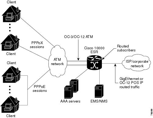
The Cisco 10000 series router supports the Layer 2 access concentrator (LAC) feature. When configured as the LAC, the Cisco 10000 series router functions as the service provider's network access server. Remote subscribers use a local or point-to-point connection to initiate a PPPoA or PPPoE session to the LAC. The LAC terminates the physical connection and forwards the PPP session to the provider's Layer 2 Tunnel Protocol network server (LNS).
The LAC connects to the LNS using a local area network or a wide area network such as public or private ATM. The LAC directs subscriber sessions into Layer 2 Tunnel Protocol (L2TP) tunnels based on the domain of each session. The LAC acts as one side of an L2TP tunnel endpoint and is a peer to the LNS on the other side of the tunnel. The LAC forwards packets to and from the LNS and a remote system.
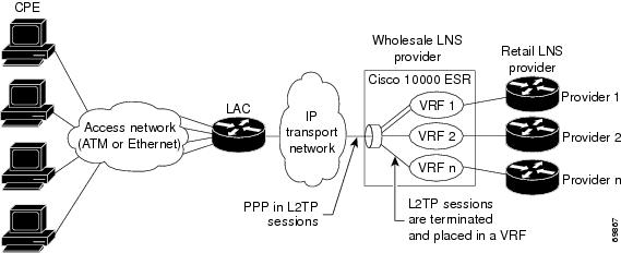
Acting as the LNS, you can configure the Cisco 10000 series router to terminate the PPP sessions and route the client IP packets onto the ISP or corporate network toward their final destination (Figure 5-1). You can also configure the LNS to place the sessions in VRFs before routing the packets, as shown in Figure 5-2.
The LAC feature is described in the following topics:
•
Required Configuration Tasks for LAC
•
•
•
•
Figure 5-1 Terminating and Forwarding Sessions from the LAC
Figure 5-2 Placing Sessions from the LAC in VRFs
Tunnel Sharing
The tunnel sharing feature enables sessions that are authorized with different domains to share the same tunnel. Tunnel sharing reduces the number of tunnels required from the LAC. When used with the L2TP multihop feature, tunnel sharing also reduces the number of tunnels to an LNS. While improving tunnel management, tunnel sharing helps to reduce the number of tunnel establishment messages that are sent after interface dropouts, reducing dropout recovery time.
Note
The domain domain-name command in request-dialin or virtual private dial network (VPDN) group configuration mode requests that the LAC tunnel PPP sessions from a specific domain-name. Applying multiple instances of this command in a VPDN group or subgroup enables the LAC to forward PPP sessions from any of the specified domains in the same tunnel.
Tunnel Service Authorization
The tunnel service authorization feature allows the service provider to limit the number of destinations a subscriber can choose and to charge a fee for each destination allowed. The LAC can conduct static or dynamic tunnel service authorization.
A static domain name on an ATM PVC port overrides the domain name that the client session supplies. Static tunnel service authorization does not support switched virtual circuits (SVCs).
If a static domain is not configured, the LAC conducts dynamic tunnel service authorization. During dynamic tunnel service authorization, the LAC performs the following steps:
1.
If the domain name is on the authorized list, the LAC proceeds to tunnel service authorization.
If the domain name is not on the authorized list, the LAC attempts PPP authentication and authorization for local termination. The vpdn authorize domain command configures the domain preauthorization feature.
2.
The following sections discuss tunnel selection as it relates to tunnel service authorization.
Tunnel Selection
When configured as the LAC, the Cisco 10000 series router selects a tunnel for an incoming PPP session using the following features:
•
•
•
Static Tunnel Selection
The static tunnel selection feature specifies a domain name for a PVC on an ATM interface. The LAC uses the specified domain name to select a tunnel for all PPP sessions originating from the PVC. This feature ignores the domains subscribers indicate in their usernames and forces the subscribers to a specific destination.
The vpn service domain-name command in ATM VC configuration mode configures the domain-name on the specified PVC. The vpn service domain-name command in ATM VC class configuration mode configures the domain-name on all virtual circuits in the VC class.
Per User Tunnel Selection
The per user tunnel selection feature specifies that the LAC use the entire structured PPP username to select a tunnel for forwarding an incoming session. Instead of sending the domain name, the LAC sends the entire structured PPP username to the authentication, authorization, and accounting (AAA) server. The AAA server provides the VPDN tunnel attributes for the user, indicating which tunnel the LAC can use to forward the session.
The authen-before-forward command in VPDN group configuration mode configures the per user tunnel selection feature.
Note
Dynamic Tunnel Selection
The dynamic tunnel selection feature enables the LAC to use the client-supplied domain in the PPP username to select a tunnel for forwarding an incoming session. You must configure a VPDN group on the LAC for each possible domain that a user might indicate.
Note
Sessions per Tunnel Limiting
The sessions per tunnel limiting feature specifies the maximum number of sessions initiated within an L2TP tunnel. The initiate-to ip command in VPDN group configuration mode configures the session per tunnel limiting feature. The command syntax is:
initiate-to ip ipaddress [limit limit-number] [priority priority-number]
Because the sessions per tunnel limiting feature enables you to specify the maximum number of VPDN sessions terminating at any L2TP network server (LNS), you can keep corporate router utilization at a more predictable level.
Session Load Balancing
The session load balancing feature enables the LAC to direct sessions across multiple LNS devices. The LAC retrieves L2TP tunnel (VPDN) information from local configuration or a RADIUS server. Both configuration methods support load balancing, but using RADIUS is more scalable than the local method. When you enable the session load balancing feature using RADIUS, the server sends L2TP tunnel information using multiple Tunnel-Server-Endpoint attributes in one tagged attribute group.
Multiple instances of the initiate-to ip command in VPDN group configuration mode configures the session load balancing feature locally. For information on the command syntax, see the "Sessions per Tunnel Limiting" section.
When you enable the session load balancing feature, the LAC uses a priority or round-robin load balancing algorithm to forward PPP sessions destined to the same domain among multiple tunnels.
Note
Session Load Failover
The session load failover feature works with the session load balancing feature to enable the LAC to direct sessions across multiple LNS devices. If the primary set of LNS devices fails, the session load failover feature enables the LAC to direct sessions to a set of failover LNS devices. The LAC uses the failover LNS devices only if all of the primary set of devices are unavailable. Failover occurs if the LAC:
•
•
•
•
The RADIUS Tunnel-Preference attribute is used to form load failover groups. When the values of the Tunnel-Preference attributes for different tagged attribute groups are the same, the Tunnel-Server-Endpoint for each of those attribute groups has the same failover priority.
Feature History for LAC
Restrictions for LAC
When configured as a LAC device, the Cisco 10000 series router has the following restrictions:
•
•
Required Configuration Tasks for LAC
To configure the Cisco 10000 series router to act as a LAC, perform the following required configuration task:
•
Enabling the LAC to Look for Tunnel Definitions
To enable the LAC to look for tunnel definitions, you must enable the VPDN feature on the LAC. To enable VPDN, enter the following commands:
Optional Configuration Tasks for LAC
To configure the Cisco 10000 series router as a LAC, perform any of the following optional tasks:
•
•
•
Enabling Sessions with Different Domains to Share the Same Tunnel
To enable sessions authorized with different domains to share the same tunnel, enter the following commands:
Verifying Tunnel Sharing Configuration on the LAC
To verify tunnel sharing configuration on the LAC, enter the following command in privileged EXEC mode:
Router# show running-config
Displays the running configuration and allows you to check that you successfully enabled the tunnel sharing feature.
Enabling the LAC to Conduct Tunnel Service Authorization
To enable the LAC to conduct static or dynamic tunnel service authorization, perform the following tasks:
•
•
•
Configuring a Static Domain Name on a Permanent Virtual Circuit
To configure a static domain name on a permanent virtual circuit (PVC), enter the following commands:
Example 5-1 shows the static domain names net1.com and net2.com assigned to PVCs on an ATM interface. All PPP sessions originating from PVC 30/33 are sent to the net1.com L2TP tunnel. All PPP sessions originating from PVC 30/34 are sent to the net2.com tunnel.
Example 5-1 Configuring a Static Domain Name on a Permanent Virtual Circuit
!interface ATM 0/0/0.33 multipointatm pppatm passivepvc 30/33encapsulation aa15ciscoppp Virtual-Template1vpn service net1.com!pvc 30/34encapsulation aa15ciscoppp Virtual-Template1vpn service net2.com!Configuring a Static Domain Name on a Virtual Circuit Class
To configure a static domain name on a VC class, enter the following commands beginning in global configuration mode:
In Example 5-2, the static domain name net.com is assigned to a VC class. The VC class is then assigned to the VCs on an ATM subinterface.
Example 5-2 Configuring a Static Domain Name on a VC Class
!vc-class ATM MyClassencapsulation aal5ciscoppp Virtual-Template1vpn service net.com!interface ATM 0/0/0.99 multipointatm pppatm passiveclass-int MyClassno ip directed-broadcastpvc 20/40pvc 30/33!Verifying the Static Domain Name
To verify that you successfully configured the static domain name, enter the show running-config command in privileged EXEC mode.
Enabling Domain Preauthorization
To enable the LAC to perform domain authorization before tunneling, enter the following commands:
Example 5-3 Enabling Domain Preauthorization
!aaa new-modelaaa authorization network default local group radius!vpdn authorize domain!radius-server host 10.16.9.9 auth-port 1645 acct-port 1646radius-server attribute nas-port format dradius-server key MyKeyradius-server vsa send authentication!Verifying Domain Preauthorization
To verify that you successfully enabled domain preauthorization, enter the following commands:
Configuring the LAC to Communicate with the RADIUS Server
To enable the LAC to communicate properly with the RADIUS server for tunnel service authorization, enter the following commands:
Example 5-4 Configuring Communication with the RADIUS Server
!aaa new-modelaaa authorization network default local group radius!radius-server host 10.16.9.9 auth-port 1645 acct-port 1646radius-server attribute 44 include-in-access-req vrf vrf1radius-server key MyKeyradius-server vsa send authenticationVerifying Communication with the RADIUS Server
To verify that you successfully configured the LAC to communicate properly with the RADIUS server for tunnel service authorization, enter the show running-config command in privileged EXEC mode.
Configuring Sessions Per Tunnel Limiting on the LAC
To limit the number of sessions per tunnel without using a RADIUS server, enter the following commands.
Note
Verifying Sessions Per Tunnel Limiting on the LAC
To verify sessions per tunnel limiting on the LAC, enter the following commands:
Example 5-5 Verifying Sessions Per Tunnel Limiting on the LAC
Router> enableRouter# show vpdn tunnelL2TP Tunnel Information (Total tunnels 50 sessions 2000)LocID RemID Remote Name State Remote Address Port Sessions41234 7811 LNS1 est 10.16.1.1 1701 4020022 2323 LNS1 est 10.16.1.1 1701 4041234 7811 LNS2 est 10.16.2.2 1701 4059765 3477 LNS2 est 10.16.3.3 1701 40!!RADIUS Server Optional Configuration Tasks for LAC
To configure the optional RADIUS server for the LAC, perform any of the following optional tasks:
•
•
•
Enabling Tunnel Sharing for RADIUS Services
To configure tunnel sharing in the RADIUS service profile, enter the following Cisco-AV pair attributes in the profile:
•
•
VPDN Group
The vpdn-group attribute specifies the group to which the service belongs. All services with matching group names are considered members of the same VPDN group. This attribute has the following syntax:
Cisco-AVpair="vpdn:vpdn-group=group-name"group-name is the group to which the service belongs.
Example 5-6 VPDN Group—RADIUS Freeware Format
Cisco-AVpair="vpdn:vpdn-group=group1"Tunnel Share
The tunnel-share attribute indicates that the tunnel sharing feature is enabled for the service.
Example 5-7 Tunnel Share—RADIUS Freeware Format
Cisco-AVpair="vpdn:tunnel-share=yes"Verifying the Tunnel Sharing Configuration in the RADIUS Service Profile
To verify the RADIUS service profile, see the user documentation for your RADIUS server.
Enabling the RADIUS Server to Conduct Tunnel Service Authorization
To enable the RADIUS server to conduct dynamic tunnel service authorization, perform the following tasks:
•
•
Configuring the RADIUS User Profile for Domain Preauthorization
To enable domain preauthorization, enter the following configuration parameters in the user profile on the RADIUS server:
Example 5-8 Configuring the RADIUS User Profile for Domain Preauthorization
user = nas-port:10.16.9.9:0/0/0/30.33{profile_id = 826profile_cycle = 1radius=Cisco {check_items = {2=cisco}reply_attributes= {9, 1="vpdn:vpd-domain-list=net1.com,net2.com"Verifying the RADIUS User Profile for Domain Preauthorization
To verify the RADIUS user profile, see your RADIUS server user documentation.
Configuring the RADIUS Service Profile for Tunnel Service Authorization
To enable tunnel service authorization, enter the following configuration parameters in the service profile on the RADIUS server:
Example 5-9 Configuring the RADIUS Service Profile for Tunnel Service Authorization
user = net1.com{profile_id = 45profile_cycle = 18member = meradius=Cisco {check_items= [2=cisco}reply_attributes= {9,1="vpdn:tunnel-id=LAC-1"9,1="vpdn:12tp-tunnel_password=MySecret"9,1="vpdn:tunnel-type=12tp"9,1="vpdn:ip-addresses=10.16.10.10"6=5}}}Verifying the RADIUS Service Profile for Tunnel Service Authorization
To verify the RADIUS service profile, see your RADIUS server user documentation.
Configuring Sessions Per Tunnel Limiting in the RADIUS Service Profile
To use a RADIUS server to limit the number of sessions per tunnel, enter the following Cisco-AVpair attributes in the RADIUS service profile:
•
•
Note
VPDN IP Addresses
The vpdn:ip-addresses attribute specifies the IP addresses of the LNS devices to receive the L2TP connections. It has the following syntax:
Cisco-AVpair = "vpdn:ip-addresses=address1[<delimiter>address2][<delimiter>address3]..."The address argument is the IP address of the LNS.
The <delimiter>, (comma) and <delimiter> (space) arguments select load sharing among IP addresses.
The <delimiter>/ (slash) argument groups IP addresses on the left side in higher priority than the right side.
Example 5-10 VPDN IP Addresses—RADIUS Freeware Format
In the following example, the LAC sends the:
•
•
•
•
If the LAC fails to establish a tunnel with any of the IP addresses in the first group, it attempts to connect to the IP addresses in the second group (10.16.4.4 and 10.16.5.5).
Cisco-AVpair="vpdn:ip-addresses=10.16.1.1,10.16.2.2,10.16.3.3/10.16.4.4,10.16.5.5"VPDN IP Address Limits
The vpdn:ip-address-limits attribute specifies the maximum number of sessions in each tunnel to the IP addresses listed with the attribute. It has the following syntax:
Cisco-AVpair = "vpdn:ip-address-limits=limit1[limit2][limit3]..."The limit argument is the maximum number of sessions per tunnel to the corresponding IP address.
Example 5-11 VPDN IP Address Limits—RADIUS Freeware Format
Cisco-AVpair="vpdn:ip-address-limits=10 20 30 40 50 ".1.1.1,10.2.2.2,10.3.3.3/10.4.4.4,10.5.5.5"
Note
Verifying Sessions Per Tunnel Limiting in the RADIUS Service Profile
To verify the RADIUS service profile, see the user documentation for your RADIUS server.
Configuration Example for LAC
The following example is a basic LAC configuration in which the LNS authenticates the PPP sessions.
Current configuration : 4882 bytes!version 12.2no service padservice timestamps debug uptimeservice timestamps log uptimeno service password-encryption!hostname c10k_mc_10005_1!no logging consoleaaa new-model!!aaa session-id commonenable password lab!username LAC1-1 nopasswordusername LNS1-1 nopasswordno spd enablefacility-alarm intake-temperature major 49facility-alarm intake-temperature minor 40facility-alarm core-temperature major 53facility-alarm core-temperature minor 45card 1/0 1gigethernet-1card 2/0 1oc12atm-1card 3/0 1oc12atm-1card 4/0 4oc3atm-1card 5/0 1gigethernet-1ip subnet-zerono ip gratuitous-arpsip host zeppelin-2 1.0.0.253ip host zeppelin-3 1.0.0.253!vpdn enable!vpdn-group 1accept-dialinprotocol pppoevirtual-template 1pppoe limit per-mac 32000pppoe limit per-vc 32000!vpdn-group LAC_1request-dialinprotocol l2tpdomain hello1initiate-to ip 103.1.1.2local name LAC1-1l2tp tunnel password 7 06121A2F424B05!!buffers small permanent 15000buffers middle permanent 12000buffers large permanent 1000!interface Loopback1no ip address!interface FastEthernet0/0/0ip address 23.3.6.3 255.255.0.0full-duplex!interface GigabitEthernet1/0/0no ip addressno ip mroute-cachenegotiation autohold-queue 4096 inhold-queue 4096 out!interface GigabitEthernet1/0/0.101encapsulation dot1Q 101ip address 103.1.1.1 255.255.255.0!interface ATM2/0/0no ip addressno ip mroute-cacheatm clock INTERNALatm sonet stm-4no atm auto-configurationno atm ilmi-keepaliveno atm address-registrationno atm ilmi-enable!interface ATM3/0/0atm pppatm passiveno ip addressno ip mroute-cacheatm clock INTERNALatm sonet stm-4no atm auto-configurationno atm ilmi-keepaliveno atm address-registrationno atm ilmi-enable!interface ATM3/0/0.41101 point-to-pointatm pppatm passivepvc 41/101encapsulation aal5snapprotocol pppoe!!interface ATM3/0/0.41102 point-to-pointpvc 41/102encapsulation aal5snapprotocol pppoe!!interface ATM3/0/0.41103 point-to-pointpvc 41/103encapsulation aal5snapprotocol pppoe!!interface ATM3/0/0.41104 point-to-pointpvc 41/104encapsulation aal5snapprotocol pppoe!!interface ATM3/0/0.41105 point-to-pointpvc 41/105encapsulation aal5snapprotocol pppoe!!interface ATM3/0/0.41106 point-to-pointpvc 41/106encapsulation aal5snapprotocol pppoe!!interface ATM3/0/0.41107 point-to-pointpvc 41/107encapsulation aal5snapprotocol pppoe!!interface ATM3/0/0.41108 point-to-pointpvc 41/108encapsulation aal5snapprotocol pppoe!!interface ATM3/0/0.41109 point-to-pointpvc 41/109encapsulation aal5snapprotocol pppoe!!interface ATM3/0/0.41110 point-to-pointpvc 41/110encapsulation aal5snapprotocol pppoe!!interface ATM3/0/0.41111 point-to-pointpvc 41/111encapsulation aal5snapprotocol pppoe!!interface ATM3/0/0.41112 point-to-pointpvc 41/112encapsulation aal5snapprotocol pppoe!!interface ATM3/0/0.41113 point-to-pointpvc 41/113encapsulation aal5snapprotocol pppoe!!interface ATM3/0/0.41114 point-to-pointpvc 41/114encapsulation aal5snapprotocol pppoe!!interface ATM3/0/0.41115 point-to-pointpvc 41/115encapsulation aal5snapprotocol pppoe!!interface ATM3/0/0.41116 point-to-pointpvc 41/116encapsulation aal5snapprotocol pppoe!!interface ATM3/0/0.41117 point-to-pointpvc 41/117encapsulation aal5snapprotocol pppoe!!interface ATM3/0/0.41118 point-to-pointpvc 41/118encapsulation aal5snapprotocol pppoe!!interface ATM3/0/0.41119 point-to-pointpvc 41/119encapsulation aal5snapprotocol pppoe!!interface ATM3/0/0.41120 point-to-pointpvc 41/120encapsulation aal5snapprotocol pppoe!!interface ATM3/0/0.41121 point-to-pointpvc 41/121encapsulation aal5snapprotocol pppoe!!interface ATM3/0/0.41122 point-to-pointpvc 41/122encapsulation aal5snapprotocol pppoe!!interface ATM3/0/0.41123 point-to-pointpvc 41/123encapsulation aal5snapprotocol pppoe!!interface ATM3/0/0.41124 point-to-pointpvc 41/124encapsulation aal5snapprotocol pppoe!!interface ATM4/0/0no ip addressno atm ilmi-keepalive!interface ATM4/0/1no ip addressno atm ilmi-keepalive!interface ATM4/0/2no ip addressno atm ilmi-keepalive!interface ATM4/0/3no ip addressno atm ilmi-keepalive!interface GigabitEthernet5/0/0no ip addressnegotiation auto!interface Virtual-Template1ip unnumbered Loopback1keepalive 30no peer default ip addressppp authentication pap!ip default-gateway 23.3.0.4ip classlessip route 1.0.0.253 255.255.255.255 23.3.0.4no ip http serverip pim bidir-enable!no cdp run!radius-server retransmit 3radius-server authorization permit missing Service-Type!line con 0exec-timeout 0 0line aux 0line vty 0 4!endMonitoring and Maintaining LAC
To monitor and maintain the LAC, enter the following commands in privileged EXEC mode:
L2TP Network Server
The Cisco 10000 series router can function as an L2TP network server (LNS). By using the managed LNS features introduced in Cisco IOS Release 12.2(4)BZ1, the Cisco 10000 series router terminates L2TP sessions from the LAC and places each session into the appropriate VRF instance based on the L2TP tunnel the session arrived in. The Cisco 10000 router then routes each session within the VRF to the destination network.
The LNS is a peer to the LAC and sits on one side of an L2TP tunnel. The LNS routes packets to and from the LAC and a destination network. Acting as the LNS, you can configure the Cisco 10000 series router to terminate the PPP sessions and route the client IP packets onto the ISP or corporate network toward their final destination (see Figure 1-1 on page 1-3). You can also configure the LNS to place the sessions in VRFs before routing the packets, as shown in Figure 5-3.
Figure 5-3 Managed LNS Topology
All of a service provider's subscribers do not share the same L2TP trunk interface. Typically, the Cisco 10000 router uses virtual local area networks (VLANs) to separate a service provider's subscriber traffic. The Cisco 10000 series router can also use permanent virtual circuits (PVCs) or a separate physical interface for each provider to separate traffic. A virtual template interface configures the user sessions in a tunnel and applies to all users in the same VRF.
The LNS feature is described in the following topics:
•
•
•
•
•
Virtual Template Interface
The virtual template interface is a logical entity that the Cisco 10000 series router applies dynamically as needed to a connection. It is a configuration for an interface, but it is not tied to the physical interface. It is used to create and configure a virtual interface known as a virtual access interface (VAI). The VAI is cloned from the virtual template interface, used on demand, and then freed when no longer needed.
For example, when a remote user initiates a PPP session to the Cisco 10000 series router, the predefined configuration template is used to configure a VAI. The VAI is created and configured dynamically using the virtual template interface. Using AAA, RADIUS attributes can further define the VAI configuration.
The VAI uses the attributes of the virtual template to create the session, which results in a VAI that is uniquely configured for a specific user. When the user is done, the VAI goes down and the resources are freed for other client uses.
Virtual Routing and Forwarding Instance
A virtual routing and forwarding (VRF) instance includes the routing information that defines a customer VPN site that is attached to a provider edge (PE) router, such as the Cisco 10000 series router. A VRF consists of an IP routing table, a derived forwarding table, a set of interfaces that use the forwarding table, and a set of rules and routing protocols that determine what goes into the forwarding table.
To configure a VRF instance, enter the rd command in VRF configuration submode to specify the correct route distinguisher (RD) used for the VPN. The RD extends the IP address so that you can identify the VPN to which it belongs.
Per VRF AAA
The per VRF AAA feature enables you to partition authentication, authorization, and accounting (AAA) services based on a VRF instance. To support the per VRF AAA feature, the RADIUS server must be VRF aware.
To be VRF aware, ISPs must define multiple instances of the same operational parameters and secure them to the VRF partitions. Securing AAA parameters to a VRF can be accomplished from one or more of the following sources:
•
•
•
For more information on the per VRF AAA feature, see the "Configuring per VRF AAA Services" section and the "RADIUS Attribute Screening" section on page 16-39.
Private Servers
Private servers are servers defined within a server group. These servers have private addresses within the default server group containing all the servers. Private servers remain hidden from other groups. If you do not specify private server parameters, global configurations are used. If you do not specify global configurations, default values are used.
You configure all server operational parameters per host, per server group, or globally. Per host configurations have precedence over per server group configurations. Per server group configurations have precedence over global configurations.
RADIUS Attribute Screening
The RADIUS Attribute Screening feature allows you to configure a list of "accept" or "reject" RADIUS attributes on the Cisco 10000 series router for authorization and accounting purposes. Based on the accept or reject list you configure for a particular purpose, the Cisco 10000 series router:
•
•
Before you configure a RADIUS accept or reject list, you must enable AAA using the aaa new-model command in global configuration mode. For more information, see the "Configuring RADIUS Attribute Accept or Reject Lists" section, the "RADIUS Attribute Screening" section on page 16-39, or see the Cisco IOS Command Summary, Volume 2 of 3, Release 12.2.
Packet Fragmentation
The setting of the Don't Fragment (DF) bit determines if a packet is eligible for fragmentation. If the DF bit is clear, a packet is fragmented only if it exceeds the maximum transfer unit (MTU) size. If the DF bit is set, a packet is not fragmented and instead is dropped. For packets entering an L2TP tunnel that exceed the MTU size, enter the following command in global configuration mode to configure the Cisco 10000 series router to ignore the setting of the DF bit and to fragment the packets:
Router(config)# [no] ip pxf ignore 12tp df-bitWhen you activate packet fragmentation, the router clears the DF bit of packets entering all L2TP tunnels and fragments the packets, but only if the packets exceed the session MTU. Clearing the DF bit allows packets to be fragmented. If a packet enters an L2TP tunnel, but it does not exceed the MTU, the router does not clear the DF bit. Instead, the DF bit is left untouched and the router does not fragment the packet.
Tunnel Accounting
The tunnel accounting feature enhances AAA accounting by adding the ability to include tunnel-related statistics in the RADIUS information. To collect tunnel usage information, RADIUS accounting includes tunnel accounting attributes and additional tunnel accounting values for the Acct-Status-Type RADIUS attribute.
Note
By using the tunnel accounting feature, you can track the services that users are accessing and the amount of network resources that they are consuming. In L2TP dial-up networks, tunneling of user sessions can be done automatically as a service of the Internet service provider (ISP). This service is used to provide remote intranet access to the employees of a corporation. ISPs collect usage information about the service, which they then can use for billing purposes and for managing the network. Tunnel accounting allows dial-up usage information to be collected and stored at a central location.
When you enable tunnel accounting on the Cisco 10000 series router, the router reports user activity to the RADIUS server in the form of accounting records. Each accounting record contains accounting attribute-value (AV) pairs. Accounting records are stored on the RADIUS server and can be analyzed for network management, client billing, and auditing. Corporations contracting with ISPs also receive a record of a user's resource consumption, which enables the corporation to audit its ISP billing statements.
Note
Tunnel Authentication
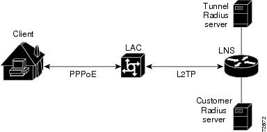
The tunnel authentication feature verifies users before they are allowed access to the network and the network services. On the LNS, L2TP tunnel authorization and authentication can occur by using the vpdn-group commands configured in the local configuration. If a large number of VPDN groups is configured, maintaining the local configuration across a number of LNS devices can be difficult. To alleviate this, the Cisco 10000 series router supports the capability to do tunnel authentication using a RADIUS server.
Figure 5-4 Tunnel Authorization and Authentication
As shown in Figure 5-4, typically, a tunnel RADIUS server is used for tunnel authorization and a separate user RADIUS server is used for RADIUS tunnel authentication. The following describes the sequence of events that occur for tunnel authorization and authentication:
1.
2.
3.
4.
5.
6.
Note
•
Named Method Lists
To configure authentication, authorization, and accounting (AAA), you first define a named list of methods and then apply that list to various interfaces. The named method list defines the types of authentication or accounting to be performed and the sequence in which they will be performed. You must apply the method list to a specific interface before any defined authentication methods are performed. The only exception is the default method list, which is automatically applied to all interfaces except those that have a named method list explicitly defined. A defined method list overrides the default method list.
An authentication method list lists the methods to be queried to authenticate users. An accounting method list lists the methods used to support accounting. Method lists enable you to designate one or more security protocols to be used for authentication or accounting, thus ensuring a backup system for authentication or accounting in case the initial method fails. Cisco IOS software uses the first listed method to authenticate users or to support accounting. If that method fails to respond, the Cisco IOS software selects the next authentication or accounting method listed in the method list. This process continues until successful communication with a listed authentication or accounting method occurs, or all methods defined in the method list are exhausted.
The Cisco IOS software attempts authentication with the next listed authentication method only when there is no response from the previous method. If authentication fails at any point in this cycle (for example, the RADIUS server responds by denying user access), the authentication process stops and no other authentication methods are attempted.
For more information, see the "Configuring Authentication" chapter in the Cisco IOS Security Configuration Guide, Release 12.2.
Framed-Route VRF Aware
The Framed-Route VRF aware feature allows you to apply static IP routes to a specific VRF table instead of the global routing table. This feature makes RADIUS Attribute 22 (Framed-Route) and a combination of Attribute 8 (Framed-IP-Address) and Attribute 9 (Framed-IP-Netmask) aware of VRF instances.
You can configure a per-user static route by using the Framed-Route attribute in any of the following ways:
•
•
Note
•
Note
Feature History for LNS
Restrictions for the LNS
To function as a LNS, the Cisco 10000 series router has the following restrictions:
•
•
The configured police bps rate when applied to an L2TP virtual access interface includes the following 40 bytes of per packet overhead:
–
–
–
–
Prerequisites for LNS
To function as an LNS, the Cisco 10000 series router has the following requirements:
•
–
–
Note
Required Configuration Tasks for LNS
To configure the Cisco 10000 series router as an LNS, perform the following required configuration tasks:
•
•
Note
Configuring the Virtual Template Interface
To configure a virtual template interface, enter the following commands:
Configuring the LNS to Initiate and Receive L2TP Traffic
To configure the Cisco 10000 router, acting as the LNS, to initiate and receive L2TP traffic, enter the following commands:
Example 5-12 Configuring the LNS
!Configures the VRF.ip vrf vpn-1rd 1100:1!!Configures the virtual template interface and associates the VRF to it.interface virtual-template 1ip vrf forwarding vpn-1ip unnumbered loopbackppp authentication chap!!Configures a VPDN group to ensure that all the sessions for a particular tunnel get the same virtual template and thus the same VRF.vpdn enablevpdn-group 1accept-dialinprotocol 12tpvirtual-template 1terminate-from hostname lac1-vpn1local name r4-112tp tunnel password 7 1511021F072512tp tunnel receive-window 10012tp tunnel retransmit retries 712tp tunnel retransmit timeout min 2Optional Configuration Tasks for LNS
To configure the Cisco 10000 series router as an LNS, perform as many of the following configuration tasks as desired. All of these configuration tasks are optional.
•
•
•
•
•
Configuring per VRF AAA Services
To configure per VRF AAA services, perform the following tasks:
•
•
Note
Enabling AAA
To enable AAA, enter the following commands.
Note
Step 1
Router> enable
Enters privileged EXEC mode.
Step 2
Router# config terminal
Enters global configuration mode.
Step 3
Router(config)# aaa new model
Enables AAA.
Configuring Private Server Parameters
To configure private server operational parameters, enter the following commands:
Configuring AAA for the VRF
To configure AAA for the VRF, enter the following commands:
Configuring RADIUS-Specific Commands for the VRF
To configure AAA global RADIUS-specific commands for the VRF definition, enter the following commands:
Step 1
Router> enable
Enters privileged EXEC mode.
Step 2
Router# config terminal
Enters global configuration mode.
Step 3
Router(config)# interface virtual-template number
Configures a virtual template interface and enters interface configuration mode.
Step 4
Router(config-if)# ip vrf forwarding vrf-name
Associates a VRF instance with a virtual template interface.
The vrf-name argument is the name assigned to a VRF.
Step 5
Router(config-if)# ppp authentication {protocol1 [protocol2...]} list-name
Enables Challenge Handshake Authentication Protocol (CHAP) or Password Authentication Protocol (PAP) or both and specifies the order in which CHAP and PAP authentication are selected on the interface.
The protocol1[protocol2...] argument specifies at least one of the following keywords:
•
•
•
The list-name argument (optional) specifies the name of a list of methods of authentication to use. This is the same name you specified in step 4 of the "Configuring AAA for the VRF" section. If no list name is specified, the system uses the default. Create the list by using the aaa authentication ppp command.
Step 6
Router(config-if)# ppp authorization list-name
Enables AAA authorization on the selected interface.
The list-name argument (optional) specifies the name of a list of authorization methods to use. If no list name is specified, the system uses the default. Create the list by using the aaa authorization command.
Step 7
Router(config-if)# ppp accounting list-name
Enables AAA accounting services on the selected interface.
Step 8
Router(config-if)# exit
Exits interface configuration mode.
Step 9
Router(config)# ip radius source-interface subinterface-name vrf vrf-name
Forces RADIUS to use the IP address of a specified interface for all outgoing RADIUS packets and enables the specification on a per VRF basis.
The subinterface-name argument specifies the name of the interface that RADIUS uses for all of its outgoing packets.
The vrf vrf-name keyword and argument specify the per VRF configuration.
Step 10
Router(config)# radius-server attribute 44 include-in-access-req vrf vrf-name
Sends RADIUS attribute 44 in access request packets before user authentication and enables the specification on a per VRF basis.
The vrf vrf-name keyword and argument specify the per VRF configuration.
Step 11
Router(config)# radius-server domain-stripping vrf vrf-name
(Optional) Enables VRF-aware domain-stripping.
The vrf vrf-name keyword and argument specify the per VRF configuration.
Verifying and Troubleshooting per VRF AAA
To verify and troubleshoot the per VRF AAA feature, enter the following commands in privileged EXEC mode.
Note
Caution
Configuring a VRF on the LNS
To configure a VRF, enter the following commands:
For more information about configuring a VRF, see the "Configuring Multiprotocol Label Switching chapter in the Cisco IOS Switching Services Configuration Guide, Release 12.2.
Configuring Sessions per Tunnel Limiting on the LNS
To limit the number of sessions per tunnel without using a RADIUS server, enter the following commands:
Verifying Sessions per Tunnel Limiting on the LNS
To verify sessions per tunnel limiting on the LNS, enter the following commands:
Configuring RADIUS Attribute Accept or Reject Lists
To configure a RADIUS attribute accept or reject list for authorization or accounting, enter the following commands:
Verifying RADIUS Attribute Accept or Reject Lists
To verify an accept or reject list, enter any of the following commands in privileged EXEC mode:
Caution
Configuring the LNS for RADIUS Tunnel Accounting
To configure the LNS for RADIUS tunnel accounting, perform the following required configuration tasks:
•
•
Configuring AAA Accounting Using Named Method Lists
To configure AAA accounting using named method lists, enter the following commands beginning in global configuration mode:
Note
Configuring RADIUS for Tunnel Accounting
Cisco IOS Release 12.2(15)BX enhances the AAA accounting feature by adding the ability to include tunnel-related statistics in the RADIUS information. To collect tunnel usage information, you must configure the following attributes on the RADIUS server:
•
•
Table 5-1 describes the values for the Acct-Status-Type attribute that support tunnel accounting on the RADIUS server.
Example 5-13 is an example of Tunnel-Start accounting record sent by the LNS to the RADIUS server.
Example 5-13 Tunnel-Start Accounting Record
User-Name = LNS1/LAC1NAS-IP-Address = 23.1.2.10Service-Type = FramedFramed-Protocol = PPPTunnel-Type_tag0 = L2TPTunnel-Medium-Type_tag0 = IPv4Tunnel-Client-Endpoint_tag0 = 10.2.2.1Tunnel-Server-Endpoint_tag0 = 10.2.2.2Acct-Status-Type = Tunnel-StartAcct-Delay-Time = 0Acct-Session-Id = 00000B3DAcct-Authentic = RADIUSTunnel-Client-Auth-ID_tag0 = LAC1Tunnel-Server-Auth-ID_tag0 = LNS1Acct-Tunnel-Connection = 63708/13441Example 5-14 is an example of a Tunnel-Stop accounting record sent by the LNS to the RADIUS server.
Example 5-14 Tunnel-Stop Accounting Record
User-Name = LNS1/LAC1NAS-IP-Address = 23.1.2.10Service-Type = FramedFramed-Protocol = PPPAscend-Multilink-ID = 2877Ascend-PreSession-Time = 0Tunnel-Type_tag0 = L2TPTunnel-Medium-Type_tag0 = IPv4Tunnel-Client-Endpoint_tag0 = 10.2.2.1Tunnel-Server-Endpoint_tag0 = 10.2.2.2Ascend-Pre-Input-Packets = 0Ascend-Pre-Input-Octets = 0Acct-Status-Type = Tunnel-StopAcct-Delay-Time = 0Acct-Input-Octets = 108276Acct-Output-Octets = 65986Acct-Session-Id = 00000B3DAcct-Authentic = RADIUSAcct-Session-Time = 57Acct-Input-Packets = 2578Acct-Output-Packets = 2823Acct-Terminate-Cause = NAS ErrorAcct-Multi-Session-Id = 00000B3DTunnel-Client-Auth-ID_tag0 = LAC1Tunnel-Server-Auth-ID_tag0 = LNS1Ascend-Connect-Progress = Call-UpAcct-Tunnel-Connection = 63708/13441Ascend-Disconnect-Cause = No-ReasonAcct-Tunnel-Packets-Lost = 0Ascend-Pre-Output-Octets = 0Ascend-Pre-Output-Packets = 0For more information about the RADIUS tunnel accounting attributes or the Acct-Status-Type values that support RADIUS tunnel accounting, see RFC 2867, RADIUS Accounting Modifications for Tunnel Protocol Support.
For information about RADIUS accounting attributes supported on the Cisco 10000 series router, see Appendix A, "RADIUS Attributes".
For information about RADIUS attributes, see the "RADIUS Attributes" appendix in the Cisco IOS Security Configuration Guide, Release 12.2.
For more information on configuring RADIUS, see your RADIUS user documentation.
Configuring Optional RADIUS Tunnel Accounting Features
To configure RADIUS tunnel accounting, you can also perform any of the following optional configuration tasks:
•
•
•
•
•
•
•
•
•
•
•
Note
Configuring the LNS for RADIUS Tunnel Authentication
To configure the LNS for RADIUS tunnel authentication, perform the following required configuration tasks:
•
•
•
Note
Configuring RADIUS Tunnel Authentication Method Lists on the LNS
To configure method lists on the LNS for RADIUS tunnel authentication, enter the following commands beginning in global configuration mode:
Configuring AAA Authentication Methods
To configure AAA authentication methods, do the following:
Step 1
Step 2
Step 3
Step 4
The Configuring Authentication" chapter in the Cisco IOS Security Configuration Guide, Release 12.2 describes how to configure the following authentication methods:
•
•
•
•
•
•
•
•
•
•
•
•
Configuring Vendor-Specific Attributes on RADIUS
Cisco IOS Release 12.2(15)BX adds Cisco-specific VPDN RADIUS attributes to support RADIUS tunnel authentication. To configure the RADIUS server for tunnel authentication, you must configure the following vendor-specific attributes (VSAs) on the RADIUS server:
•
Cisco:Cisco-Avpair = "vpdn:vpdn-vtemplate = <vtemplate number>"•
Cisco:Cisco-Avpair = "vpdn:dout-dialer = <LAC dialer number>"•
Service-Type = Outbound
Note
•
Example 5-15 is a RADIUS configuration that allows the LNS to terminate L2TP tunnels from a LAC. In this configuration, VirtualTemplate10 is used to clone a virtual access interface (VAI) on the LNS.
Example 5-15 Configuring RADIUS for LNS Termination of L2TP Tunnels from a LAC
myLACname Password = "cisco"Service-Type = Outbound,Tunnel-Type = :0:l@TP,Tunnel-Medium-Type = :o:IP,Tunnel-Client-Auth-ID = :0:"myLACname",Tunnel-Password = :0:"mytunnelpassword",Cisco:Cisco-Avpair = "vpdn:vpdn-vtemplate=10"Example 5-16 is an LNS configuration that supports RADIUS tunnel authentication. In this configuration, a RADIUS server group is defined using the aaa group server radius VPDN-Group command. The aaa authorization network mymethodlist group VPDN-Group command queries RADIUS for network authorization.
Example 5-16 Configuring the LNS to Support RADIUS Tunnel Authentication
aaa group server radius VPDN-Groupserver 64.102.48.91 auth-port 1645 acct-port 1646aaa authorization network mymethodlist group VPDN-Groupvpdn tunnel authorization network mymethodlistvpdn tunnel authorization virtual-template 10Configuration Examples for LNS
This section provides example configurations for the following features:
•
•
•
Managed LNS Configuration Example
Example 5-17 is an example of how to configure the Managed LNS features on the Cisco 10000 series router. In this example, the Cisco 10000 series router terminates the tunnel from the LAC and associates the VRFs with the interfaces and the virtual template interfaces. This configuration also configures RADIUS attribute screening and AAA accounting for the VRFs.
Example 5-17 Configuring Managed LNS on the Cisco 10000 Series Router
!Enables AAA.aaa new-model!!Configures private server parameters.aaa group server radius vpn1server-private 192.168.1.128 auth-port 1645 acct-port 1646 key ciscoserver-private 192.168.2.128 auth-port 1645 acct-port 1646 timeout 10 retransmit 3 key!Configures RADIUS attribute screening.cisco1authorization reject vpn1-autho-listaccounting reject vpn1-account-listip vrf forwarding vpn1!!Configures private server parameters.aaa group server radius vpn2server-private 192.168.1.128 auth-port 1645 acct-port 1646 key ciscoserver-private 192.168.2.128 auth-port 1645 acct-port 1646 timeout 10 retransmit 3 key cisco1ip vrf forwarding vpn2!!Configures AAA accounting for the VRFs.aaa authentication ppp vpn1 group vpn1aaa authentication ppp vpn2 group vpn2aaa authorization network vpn1 group vpn1aaa authorization network vpn2 group vpn2aaa accounting update periodic 1aaa accounting network vpn1 start-stop group vpn1aaa accounting network vpn2 start-stop group vpn2aaa accounting system default vrf vpn1 start-stop group vpn1aaa accounting system default vrf vpn2 start-stop group vpn2aaa session-id common!!Configures the VRFs.ip vrf vpn1rd 1100:1!ip vrf vpn2rd 1100:2vpdn enable!!Terminates the tunnel from the LAC.vpdn-group 1accept-dialinprotocol l2tpvirtual-template 1terminate-from hostname lac1-vpn1local name r4-1lcp renegotiation on-mismatchl2tp tunnel password 7 1511021F0725l2tp tunnel receive-window 100l2tp tunnel retransmit retries 7l2tp tunnel retransmit timeout min 2!!Terminates the tunnel from the LAC.vpdn-group 2accept-dialinprotocol l2tpvirtual-template 2terminate-from hostname lac1-vpn2local name r4-2lcp renegotiation on-mismatchl2tp tunnel password 7 121A0C041104l2tp tunnel receive-window 100l2tp tunnel retransmit retries 7l2tp tunnel retransmit timeout min 2!!!Associates the VRF with the interface.interface Loopback1ip vrf forwarding vpn1ip address 10.1.1.1 255.255.255.255!interface Loopback2ip vrf forwarding vpn2ip address 10.1.2.1 255.255.255.255!interface FastEthernet0/0/0no ip addressshutdown!!Configures the interface used to connect to the LAC.interface GigabitEthernet6/0/0ip address 10.1.1.45 255.255.255.0negotiation auto!interface GigabitEthernet7/0/0no ip addressnegotiation auto!!Associates the VRF with the interface.interface GigabitEthernet7/0/0.1encapsulation dot1Q 11ip vrf forwarding vpn1ip address 192.168.1.1 255.255.255.0!interface GigabitEthernet7/0/0.2encapsulation dot1Q 12ip vrf forwarding vpn2ip address 192.168.2.1 255.255.255.0!!Associates the VRF with the virtual template interface.interface Virtual-Template1ip vrf forwarding vpn1ip unnumbered Loopback1no peer default ip addressppp authentication chap vpn1ppp authorization vpn1ppp accounting vpn1!!Associates the VRF with the virtual template interface.interface Virtual-Template2ip vrf forwarding vpn2ip unnumbered Loopback2no peer default ip addressppp authentication chap vpn2ppp authorization vpn2ppp accounting vpn2!!Enters the VRFs in the routing table.ip classlessip route vrf vpn1 192.168.4.2 255.255.255.0 192.168.5.3ip route vrf vpn2 192.168.4.2 255.255.255.0 192.168.5.4no ip http serverip pim bidir-enable!!Configures RADIUS-specific command for the VRF to force RADIUS to use the IP address of a!specified interface for all outgoing RADIUS packets.ip radius source-interface GigabitEthernet7/0/0.1 vrf vpn1ip radius source-interface GigabitEthernet7/0/0.2 vrf vpn2no cdp run!!radius-server retransmit is on by default and cannot be removed.radius-server retransmit 3!Configures optional features such as domain-name stripping and RADIUS attribute filter.radius-server domain-stripping vrf vpn1radius-server domain-stripping vrf vpn2radius-server attribute 44 include-in-access-req vrf vpn1radius-server attribute 44 include-in-access-req vrf vpn2radius-server attribute list vpn1-autho-listattribute 26,200-220!radius-server attribute list vpn1-account-listattribute 60-70!Tunnel Accounting Configuration Examples
This section provides the following configuration examples:
•
•
LNS Tunnel Accounting Configuration Example
Example 5-18 shows how to configure the LNS to send tunnel accounting records to the RADIUS server.
Example 5-18 Configuring the LNS for Tunnel Accounting
aaa new-model!!aaa accounting network m1 start-stop group radiusaaa accounting network m2 stop-only group radiusaaa session-id commonenable secret 5 $1$ftf.$wE6Q5Yv6hmQiwL9pizPCg1!username ENT_LNS password 0 tunnelpassusername user1@cisco.com password 0 labusername user2@cisco.com password 0 labspe 1/0 1/7firmware location system:/ucode/mica_port_firmwarespe 2/0 2/9firmware location system:/ucode/mica_port_firmware!!resource-pool disableclock timezone est 2!ip subnet-zerono ip domain-lookupip host CALLGEN-SECURITY-V2 10.24.80.28 10.47.0.0ip host dirt 172.16.1.129!vpdn enablevpdn tunnel accounting network m1vpdn session accounting network m1!vpdn-group 1accept-dialinprotocol l2tpvirtual-template 1terminate-from hostname ISP_LAClocal name ENT_LNS!isdn switch-type primary-5ess!!fax interface-type modemmta receive maximum-recipients 0!interface Loopback0ip address 172.16.0.101 255.255.255.0!interface Loopback1ip address 192.168.0.101 255.255.255.0!interface Ethernet0ip address 10.1.26.71 255.255.255.0no ip mroute-cacheno cdp enable!interface Virtual-Template1ip unnumbered Loopback0peer default ip address pool vpdn-pool1ppp authentication chap!interface Virtual-Template2ip unnumbered Loopback1peer default ip address pool vpdn-pool2ppp authentication chap!interface FastEthernet0no ip addressno ip mroute-cacheshutdownduplex autospeed autono cdp enable!ip local pool vpdn-pool1 172.16.5.1 172.16.128.100ip local pool vpdn-pool2 10.0.0.1 10.0.0.100ip default-gateway 10.1.26.254ip classlessip route 0.0.0.0 0.0.0.0 10.1.26.254ip route 192.168.1.2 255.255.255.255 10.1.26.254no ip http serverip pim bidir-enable!!dialer-list 1 protocol ip permitno cdp run!!radius-server host 172.16.192.80 auth-port 1645 acct-port 1646 key rad123radius-server retransmit 3call rsvp-syncRADIUS Tunnel Accounting Records
Example 5-19 and Example 5-20 show RADIUS tunnel accounting record types.
Example 5-19 RADIUS Tunnel Accounting Record
User-Name = gomer1@hello101NAS-IP-Address = 23.1.2.10NAS-Port = 550Service-Type = FramedFramed-Protocol = PPPAscend-Multilink-ID = 2877Tunnel-Type_tag0 = L2TPTunnel-Medium-Type_tag0 = IPv4Tunnel-Client-Endpoint_tag0 = 10.2.2.1Tunnel-Server-Endpoint_tag0 = 10.2.2.2Acct-Status-Type = Tunnel-Link-StartAcct-Delay-Time = 0Acct-Session-Id = 00000B42Acct-Authentic = RADIUSAcct-Multi-Session-Id = 00000B3DTunnel-Client-Auth-ID_tag0 = LAC1Tunnel-Server-Auth-ID_tag0 = LNS1NAS-Port-Type = VirtualAcct-Tunnel-Connection = 1088401809Example 5-20 RADIUS Tunnel Accounting Record
Wed, 15 Jan 2003 16:34:27User-Name = gomer1@hello101NAS-IP-Address = 23.1.2.10NAS-Port = 550Service-Type = FramedFramed-Protocol = PPPAscend-Multilink-ID = 2877Ascend-PreSession-Time = 0Tunnel-Type_tag0 = L2TPTunnel-Medium-Type_tag0 = IPv4Tunnel-Client-Endpoint_tag0 = 10.2.2.1Tunnel-Server-Endpoint_tag0 = 10.2.2.2Ascend-Pre-Input-Packets = 0Ascend-Pre-Input-Octets = 0Acct-Status-Type = Tunnel-Link-StopAcct-Delay-Time = 0Acct-Input-Octets = 462Acct-Output-Octets = 293Acct-Session-Id = 00000B42Acct-Authentic = RADIUSAcct-Session-Time = 45Acct-Input-Packets = 11Acct-Output-Packets = 12Acct-Terminate-Cause = User RequestAcct-Multi-Session-Id = 00000B3DAcct-Link-Count = 250Tunnel-Client-Auth-ID_tag0 = LAC1Tunnel-Server-Auth-ID_tag0 = LNS1Ascend-Connect-Progress = LAN-Session-UpNAS-Port-Type = VirtualAcct-Tunnel-Connection = 1088401809Ascend-Disconnect-Cause = PPP-Rcv-Terminate-ReqAscend-Num-In-Multilink = 250Acct-Tunnel-Packets-Lost = 0Ascend-Pre-Output-Octets = 0Ascend-Pre-Output-Packets = 0
Note
Tunnel Authentication Configuration Examples
This section provides the following tunnel authentication configuration examples:
•
•
LNS Configuration to Support RADIUS Tunnel Authentication
The following example is an LNS configuration that supports RADIUS tunnel authentication. In this configuration, a RADIUS server group is defined by using the aaa group server radius VPDN-Group command. The aaa authorization network mymethodlist group VPDN-Group command queries RADIUS for network authorization.
aaa group server radius VPDN-Groupserver 64.102.48.91 auth-port 1645 acct-port 1646aaa authorization network mymethodlist group VPDN-Groupvpdn tunnel authorization network mymethodlistvpdn tunnel authorization virtual-template 10RADIUS Configuration to Support Tunnel Authentication
The following example is a RADIUS configuration that allows the LNS to terminate L2TP tunnels from a LAC. In this configuration, VirtualTemplate10 is used to clone a VAI on the LNS.
myLACname Password = "cisco"
Service-Type = Outbound,
Tunnel-Type = :0:l@TP,
Tunnel-Medium-Type = :o:IP,
Tunnel-Client-Auth-ID = :0:"myLACname",
Tunnel-Password = :0:"mytunnelpassword",
Cisco:Cisco-Avpair = "vpdn:vpdn-vtemplate=10"
Note
Monitoring and Maintaining LNS
To monitor and maintain the features configured on the LNS, enter the following commands in privileged EXEC mode:
Caution