-
Cisco 10000 Series Router Software Configuration Guide
-
About This Guide
-
Broadband Aggregation and Leased-Line Overview
-
Scalability and Performance
-
Configuring Remote Access to MPLS VPN
-
Configuring Multiprotocol Label Switching
-
Configuring the Layer 2 Tunnel Protocol Access Concentrator and Network Server
-
Configuring PPPoE over Ethernet and IEEE 802.1Q VLAN
-
Configuring IP Unnumbered on IEEE 802.1Q VLANs
-
Configuring ATM Permanent Virtual Circuit Autoprovisioning
-
Configuring the Multihop Feature
-
Configuring Address Pools
-
Configuring Local AAA Server, User Database--Domain to VRF
-
Configuring Traffic Filtering
-
Unicast Reverse Path Forwarding
-
Configuring Automatic Protection Switching
-
Configuring IP Multicast
-
Configuring RADIUS Features
-
Cisco 10000 Series Router PXF Stall Monitor
-
SSO - BFD
-
Configuring Link Noise Monitoring
-
Configuring L2 Virtual Private Networks
-
Configuring L2VPN Interworking
-
Configuring Multilink Point-to-Point Protocol Connections
-
Configuring Gigabit EtherChannel Features
-
Configuring IP Version 6
-
Configuring Template ACLs
-
Protecting the Router from DoS Attacks
-
IP Tunneling
-
RADIUS Attributes
-
Glossary
-
 Feedback
Table Of Contents
Configuring Multiprotocol Label Switching
BGP Multipath Load Sharing for eBGP and iBGP in an MPLS VPN
Feature History for BGP Multipath Load Sharing for eBGP and iBGP in an MPLS VPN
Restrictions for BGP Multipath Load Sharing for eBGP and iBGP in an MPLS VPN
Prerequisites for BGP Multipath Load Sharing for eBGP and iBGP in an MPLS VPN
Configuring IGP Convergence Acceleration
Configuring BGP Multipath Load Sharing for eBGP and iBGP in an MPLS VPN
Configuring Multipath Load Sharing for eBGP and iBGP
Verifying Multipath Load Sharing for eBGP and iBGP
Configuration Examples for BGP Multipath Load Sharing for eBGP and iBGP in an MPLS VPN
eBGP and iBGP Multipath Load Sharing Configuration Example
Verifying eBGP and iBGP Multipath Load Sharing
Monitoring and Maintaining BGP Multipath Load Sharing for eBGP and iBGP
Feature History for IPv6 VPN over MPLS
Prerequisites for Implementing IPv6 VPN over MPLS
Restrictions for Implementing IPv6 VPN over MPLS
Configuration Tasks for Implementing IPv6 VPN over MPLS
Configuration Example for Implementing IPv6 VPN over MPLS
Monitoring and Maintaining IPv6 VPN over MPLS
Application of VPDN Parameters to VPDN Groups
Feature History for Session Limit Per VRF
Restrictions for Session Limit Per VRF
Prerequisites for Session Limit Per VRF
Configuring Session Limit Per VRF
Verifying a Session Limit Per VRF Configuration
Configuration Examples for Session Limit Per VRF
Monitoring and Maintaining Session Limit Per VRF
Reverse Path Forwarding Check Support
Feature History for Half-Duplex VRF
Restrictions for Half-Duplex VRF
Prerequisites for Half-Duplex VRF
Configuration Tasks for Half-Duplex VRF
Configuring Upstream and Downstream VRFs on the L2TP Access Concentrator and PE Router
Configuration Examples for Half-Duplex VRF
Hub and Spoke Sample Configuration with Half-Duplex VRFs
Monitoring and Maintaining Half-Duplex VRF
Configuring Multiprotocol Label Switching
Multiprotocol label switching (MPLS) combines the performance and capabilities of Layer 2 (data link layer) switching with the proven scalability of Layer 3 (network layer) routing. MPLS enables service providers to meet the challenges of explosive growth in network utilization while providing the opportunity to differentiate services without sacrificing the existing network infrastructure. The MPLS architecture is flexible and can be employed in any combination of Layer 2 technologies. MPLS support is offered for all Layer 3 protocols, and scaling is possible well beyond that typically offered in today's networks.
This chapter describes the following MPLS-related features:
•
BGP Multipath Load Sharing for eBGP and iBGP in an MPLS VPN
For more information about MPLS, see Chapter 3, "Configuring Remote Access to MPLS VPN" and see the Multiprotocol Label Switching on Cisco Routers, Release 12.1(3)T feature module.
BGP Multipath Load Sharing for eBGP and iBGP in an MPLS VPN
Load sharing is a concept that allows the Cisco 10000 series router to take advantage of multiple best paths to a given destination. The paths are derived either statically or with dynamic protocols such as RIP, BGP, OSPF, and IGRP. The best path algorithm decides which is the best path to install in the IP routing table and to use for forwarding traffic.
The BGP Multipath Load Sharing for eBGP and iBGP in an MPLS VPN feature allows you to configure multipath load sharing with both external Border Gateway Protocol (eBGP) and internal BGP (iBGP) paths in BGP networks that are configured to use Multiprotocol Label Switching (MPLS) Virtual Private Networks (VPNs). BGP Multipath Load Sharing provides improved load sharing deployment and service offering capabilities and is useful for multihomed autonomous systems and provider edge (PE) routers that import both eBGP and iBGP paths from multihomed and stub networks.
BGP installs up to the maximum number of paths allowed (configured using the maximum-paths command). BGP uses the best path algorithm to select one multipath as the best path, insert the best path into the routing information base (RIB), and advertise the best path to BGP peers. Other multipaths may be inserted into the RIB, but only one path is selected as the best path.
Note
Cisco Express Forwarding (CEF) uses the multipaths to perform load sharing, which can be performed on a per-packet or per-source/destination pair basis. By default, the BGP Multipath Load Sharing for Both eBGP and iBGP in an MPLS VPN feature performs unequal cost load sharing by selecting BGP paths that do not have an equal cost of the Interior Gateway Protocol (IGP). To enable the feature, configure the router with MPLS VPNs that contain virtual routing and forwarding instances (VRFs) that import both eBGP and iBGP paths. You can configure the number of multipaths separately for each VRF.
Note
The BGP Multipath Load Sharing for eBGP and iBGP in an MPLS VPN feature is described in the following topics:
•
•
•
•
•
•
Feature History for BGP Multipath Load Sharing for eBGP and iBGP in an MPLS VPN
Restrictions for BGP Multipath Load Sharing for eBGP and iBGP in an MPLS VPN
The BGP Multipath Load Sharing for Both eBGP and iBGP in an MPLS VPN feature has the following restrictions:
•
In recursive load sharing, the information required to forward a packet requires at least 2 lookups. The first lookup determines which provider edge (PE) router is used to reach the final destination. The second lookup determines how to reach the PE router (from first lookup).
When you configure MPLS VPN, CEF uses recursive load sharing. The first lookup provides the VPN label, the second lookup provides the IGP label. When PXF forwards a packet, it does only 1 lookup which provides both a VPN and an IGP label; 2 lookups in CEF are combined into 1. The restriction for recursive load sharing when PXF forwards a packet is as follows.
When there are multiple IGP paths between a Cisco 10000 Series PE router to a provider router (P), only per-tag load sharing is supported. That is, PXF is programmed with only one of the paths and this one path is chosen in a round-robin fashion. Because the path is chosen at prefix setup time, it is not possible to predict which path will be selected for which prefix. The path selected depends on the order in which the prefixes are configured in the routing table. The bandwidths of the IGP paths are not considered in the path selection.
•
•
Prerequisites for BGP Multipath Load Sharing for eBGP and iBGP in an MPLS VPN
The BGP Multipath Load Sharing for Both eBGP and iBGP in an MPLS VPN feature has the following requirements:
•
IGP Convergence Acceleration
From Cisco IOS Release 12.2(33)SB onward, Cisco 10000 series routers support IGP and VPN load balancing for MPLS VPN scenarios on PRE3 and PRE4 engines. This support allows faster failover of IGP routes during load balancing. Therefore, for equal cost paths (load-balanced case), convergence is within an acceptable range.
For unequal cost paths, convergence depends on the number of BGP prefixes; a failover can be more than 30 seconds. From Cisco IOS Release 12.2(33)SB3 onward, Cisco 10000 series routers also support unequal cost paths.
The IGP Convergence Acceleration feature leverages the load balance infrastructure of equal paths for unequal paths. An indirection object is inserted for table output chain building. When the interface goes down, the routing protocols purge their routes and the inplace modifier prevents marking of labels with incomplete adjacency. Therefore, the indirection object can use the new adjacency labels. This update in the IGP Convergence Acceleration feature makes the convergence independent of the number of BGP prefixes, thereby allowing a faster failover.
Configuring IGP Convergence Acceleration
To configure the IGP Convergence Acceleration feature for unequal cost paths, enter the following commands beginning in global configuration mode:
Configuring BGP Multipath Load Sharing for eBGP and iBGP in an MPLS VPN
To configure the BGP Multipath Load Sharing for Both eBGP and iBGP in an MPLS VPN feature, perform the following configuration tasks:
•
•
Configuring Multipath Load Sharing for eBGP and iBGP
To configure iBGP and eBGP routes for multipath load sharing, enter the following commands beginning in global configuration mode:
Example 4-1 shows how to configure a VRF named main for an IPv4 session and configures a router to select 4 eBGP or iBGP paths as multipaths in address family configuration mode.
Example 4-1 Configuring eBGP and iBGP Multipath Load Sharing
Router(config)# router bgp 50Router(config-router)3 address-family ipv4 vrf mainRouter(config-router-af)# maximum-paths eibgp 4Verifying Multipath Load Sharing for eBGP and iBGP
To verify that iBGP and eBGP routes are configured for load sharing, enter any of the following commands in privileged EXEC mode:
Configuration Examples for BGP Multipath Load Sharing for eBGP and iBGP in an MPLS VPN
This section provides the following configuration examples:
•
•
eBGP and iBGP Multipath Load Sharing Configuration Example
Example 4-2 configures a router to select six eBGP or iBGP paths as multipaths in address family configuration mode:
Example 4-2 Configuring eBGP and iBGP Multipath Load Sharing
Router(config)# router bgp 100Router(config-router)# address-family ipv4 vrf vrf-1Router(config-router-af)# maximum-paths eibgp 6Verifying eBGP and iBGP Multipath Load Sharing
Example 4-3 shows sample output displayed when you enter the show ip bgp vpnv4 command. The third line of output (Multipath:eiBGP) indicates that multipath load sharing is on.
Example 4-3 Verifying eBGP and iBGP Multipath Load Sharing
Router# show ip bgp vpnv4 all 10.22.22.0BGP routing table entry for 10:1:22.22.22.0/24, version 19Paths: (5 available, best #5)Multipath:eiBGPAdvertised to non peer-group peers:10.0.0.2 10.0.0.3 10.0.0.4 10.0.0.52210.0.0.0 (metric 20) from 10.0.0.4 (10.0.0.4)Origin IGP, metric 0, localpref 100, valid, internal, multipathExtended Community:0x0:0:0 RT:100:1 0x0:0:0Originator:10.0.0.2, Cluster list:10.0.0.42210.0.0.2 (metric 20) from 10.0.0.5 (10.0.0.5)Origin IGP, metric 0, localpref 100, valid, internal, multipathExtended Community:0x0:0:0 RT:100:1 0x0:0:0Originator:10.0.0.2, Cluster list:10.0.0.52210.0.0.2 (metric 20) from 10.0.0.2 (10.0.0.2)Origin IGP, metric 0, localpref 100, valid, internal, multipathExtended Community:RT:100:1 0x0:0:02210.0.0.2 (metric 20) from 10.0.0.3 (10.0.0.3)Origin IGP, metric 0, localpref 100, valid, internal, multipathExtended Community:0x0:0:0 RT:100:1 0x0:0:0Originator:10.0.0.2, Cluster list:10.0.0.32210.1.1.12 from 10.1.1.12 (10.22.22.12)Origin IGP, metric 0, localpref 100, valid, internal, multipath, bestExtended Community:RT:100:1Monitoring and Maintaining BGP Multipath Load Sharing for eBGP and iBGP
To display eBGP and iBGP multipath load sharing information, enter any of the following commands in privileged EXEC mode:
IPv6 VPN over MPLS
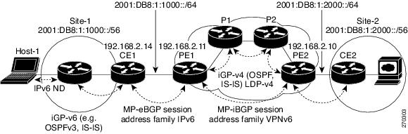
Multiprotocol BGP is the centerpiece of the MPLS IPv6 VPN architecture in IPv4 and IPv6. It is used to distribute IPv6 routes over the service provider backbone, with the same set of mechanisms to work with overlapping addresses, redistribution policies, and scalability issues. The 6VPE feature is the IOS implementation as described in RFC 4659.
IPv6 avoids overlapping address space by using either a global IPv6 Unicast prefix—RFC 3587—or Unique IPv6 Local Addressing—RFC 4193. For redistribution, a Network Layer Reachability Information (NLRI) 3-tuple, format—containing length, IPv6 prefix, and label—is defined to distribute routes using multiprotocol BGP. The extended community attribute—the route target—is used to control redistribution of routing information by tagging exported routes and filtering imported ones.
For scalability, route reflectors can be used to concentrate routing paths and avoid a full PE mesh. Similar to IPv4, BGP features in IPv6, such as route refresh, automatic route filtering, and outbound route filtering, help reduce the number of routes held in each PE.
Figure 4-1 illustrates the important aspects of the IPv6 VPN architecture.
Figure 4-1 Simple IPv6 VPN Architecture
The IPv6 VPN over MPLS (6VPE) feature is described in the following topics:
•
•
•
•
•
•
Feature History for IPv6 VPN over MPLS
Prerequisites for Implementing IPv6 VPN over MPLS
The following Cisco IOS services must be running on the network before you configure IPv6 VPN operation:
•
•
•
•
•
Restrictions for Implementing IPv6 VPN over MPLS
The 6VPE feature has the following restrictions:
•
•
•
Configuration Tasks for Implementing IPv6 VPN over MPLS
Tip
http://www.cisco.com/en/US/docs/ios/12_2t/ipv6/v6addres.htmlThe IPv6VPN over MPLS (6VPE) includes the configuration tasks in the following list. For more information about these tasks, see the Implementing IPv6 VPN over MPLS (6VPE) chapter in the Cisco IOS IPv6 Configuration Guide, Release 12.2SR at:
http://www.cisco.com/en/US/docs/ios/ipv6/configuration/guide/ip6-ov_mpls_6vpe.html
•
•
•
•
•
•
•
Note
The IPv6VPN over MPLS (6VPE) feature also supports the configuration of the following features on Cisco 10000 series routers:
•
BGP Features
The following features are supported on Cisco 10000 series routers by the IPv6 VPN over MPLS (6VPE) feature:
•
SoO is used to prevent routing loops in the case of a dual-homed CE. The 6VPE feature supports the SoO Attribute for control of IPv6 VPN routes in the same way as it is currently supported for IPv4 VPNs.
For information on configuring this feature, see the How to Configure EIGRP MPLS VPN PE-CE Site of Origin (SoO) Support section in the EIGRP MPLS VPN PE-CE Site of Origin (SoO) guide at:
•
If a global ASN is specified, BGP automatically replaces the ASN with a unique number to ensure the site is uniquely identified. The 6VPE feature supports the ASN Override BGP feature via the use of the as-override keyword in the same way as the feature is currently supported by IPv4 VPNs.
•
A BGP speaker normally ignores a received update that contains its own ASN in the AS_PATH attribute. This check must be omitted in the case of hub-and-spoke topology. The 6VPE feature supports the Allow-AS-in BGP feature via the use of the allowas-in keyword in the same way as the feature is currently supported by IPv4 VPNs.
•
The 6VPE feature supports the ability to filter MP-BGP IPv6 advertisements based on configured IPv6 prefixes.
For information on configuring this feature, see the Configuring BGP Filtering Using Prefix Lists section in the Configuring BGP chapter of the Cisco IOS IP Configuration Guide, Release 12.2 guide at:
http://www.cisco.com/en/US/docs/ios/12_2/ip/configuration/guide/1cfbgp.html#wp1001470
•
The 6VPE feature supports the ability to filter MP-BGP IPv6 advertisement based on configured AS paths.
For information on configuring this feature, see the Configuring BGP Path Filtering by Neighbor section in the Configuring BGP chapter of the Cisco IOS IP Configuration Guide, Release 12.2 guide at:
http://www.cisco.com/en/US/docs/ios/12_2/ip/configuration/guide/1cfbgp.html#wp1001644
•
The 6VPE feature supports an upper limit on the number of BGP routes that have been learned from a given CE. The 6VPE feature also supports the Max Prefix BGP feature via the use of the maximum-prefix keyword in the same way as the feature is currently supported by IPv4 VPNs.
For information on configuring this feature, see the Configuring BGP section in the Configuring BGP chapter of the Cisco IOS IP Configuration Guide, Release 12.2 guide at:
http://www.cisco.com/en/US/docs/ios/12_2/ip/configuration/guide/1cfbgp.html
•
Using BGP Route Refresh, an MP-BGP speaker (PE and/or CE) can request another BGP speaker to resend its MP-BGP updates.
For information on configuring this feature, see the Configuring BGP section in the Configuring BGP chapter of the Cisco IOS IP Configuration Guide, Release 12.2 Guide at:
http://www.cisco.com/en/US/docs/ios/12_2/ip/configuration/guide/1cfbgp.html
•
The 6VPE feature supports the Route Target Rewrite at AS Boundary feature in the same way as the feature is currently supported by IPv4 VPNs.
For information on configuring this feature, see the Inter-AS RT-Rewrite section in the Spanning Multiple Autonomous Systems chapter of the Cisco IP Solution Center MPLS VPN User Guide, 5.0 at:
•
The 6VPE feature supports eBGP Multipath, iBGP Multipath, eiBGP Multipath and the DMZ-link-bandwidth based load-balancing for IPv6 VPNs in the VPN-IPv6 address family. Load balancing is supported in the same way as they are currently supported by IPv4 VPNs in the VPN-IPv4 address family.
Note
For information on configuring this feature, see the How to Configure BGP Multipath Load Sharing for Both eBGP and iBGP in an MPLS-VPN section in the BGP Multipath Load Sharing for Both eBGP and iBGP in an MPLS-VPN guide at:
http://www.cisco.com/en/US/docs/ios/iproute/configuration/guide/irp_bgp_ebgp_ibgp.html#wp1054087
•
The 6VPE feature supports the same per-VRF BGP dampening mechanism as the one supported for IPv4 VPN, so that BGP Dampening can be separately controlled for each VRF.
For information on configuring this feature, see the Configuring Route Dampening section in the Configuring Internal BGP Features chapter of the Cisco IOS IP Routing Protocols Configuration Guide, Release 12.4 at:
http://www.cisco.com/en/US/docs/ios/12_4/ip_route/configuration/guide/1cfbgph.html#wp1002395
IPv6 Internet Access
Most VPN sites require access to the Internet. The following Internet access models are supported by IPv6 VPNs for enabling VPN access to the Internet:
•
In some VPNs, one or more of the sites can obtain Internet access using an Internet gateway, such as a firewall, attached to a non-VRF interface to an Internet service provider (ISP). The ISP may or may not be the same organization as the service provider (SP) that is providing the VPN service. Traffic to or from the Internet gateway can be routed according to the PE router's default forwarding table.
•
If a packet is received by a PE over a VRF interface and the packet's destination address does not match any route in the VRF, the packet can be matched against the PE's default forwarding table. If the packet matches the PE's default forwarding table, the packet can be forwarded natively through the backbone to the Internet instead of being forwarded by MPLS. In this model, the default forwarding table might have the full set of Internet routes, or it might have just a single default route leading to another router that does have the full set of Internet routes in its default forwarding table.
•
The static routes in VRFs can be resolved in the IPv6 Global Table in the same way they are currently supported for IPv4 VPN. Therefore, in the IPv6 VRF, the network administrator can add static routes as a default route, that points to an IPv6 Internet Gateway for outbound traffic from CE to Internet.
•
You can obtain Internet access via a VRF interface by having the VRF include the Internet routes. This model involves redistributing the Internet routes into the VRF.
VRF-Aware Router Applications
The following features are supported on Cisco 10000 series routers by the IPv6VPN over MPLS (6VPE) feature:
•
The VRF-aware Ping ping vrf [VRF name] [IPv6-address] command is supported.
•
The VRF-aware Traceroute traceroute vrf [VRF name] [IPv6-address] command is supported.
•
The VRF-aware Telnet telnet vrf [VRF name] [IPv6-address] command is supported.
VRF-Lite
VRF-lite, also known as Multi-VRF CE, is an extension of IP routing with multiple routing instances on a CE router. The VRF-lite feature performs the following functions:
•
•
•
•
VRF-lite is typically deployed along with Multiprotocol Label Switching (MPLS) VPN at the customer edge to support multiple customers on a single switch. The 6VPE feature supports the VRF-Lite feature in the same way as the feature is currently supported by IPv4 VPNs.
QoS Features
The following features are supported on Cisco 10000 series routers by the IPv6VPN over MPLS (6VPE) feature:
•
The 6VPE feature supports the same QoS mechanisms for IPv6 VPNs that is currently supported for IPv4 VPNs on the Ingress PE.
•
The 6VPE feature supports the same QoS mechanisms for IPv6 VPNs that is currently supported for IPv4 VPNs on the Egress PE.
•
The 6VPE feature supports FRF.12 fragmentation and interleaving for IPv6 traffic, in addition to IPv4 traffic, on PE to CE Frame Relay connections.
For configuration tasks, see the FRF.12 Fragmentation section in the Fragmenting and Interleaving Real-Time and Nonreal-Time Packets chapter of the Cisco 10000 Series Router Quality of Service Configuration Guide at:
http://www.cisco.com/en/US/docs/routers/10000/10008/configuration/guides/qos/10qlfi.html#wp1043021
Note
Tip
http://www.cisco.com/en/US/tech/tk436/tk428/technologies_configuration_example09186a00800a6c11.shtml
Configuration Example for Implementing IPv6 VPN over MPLS
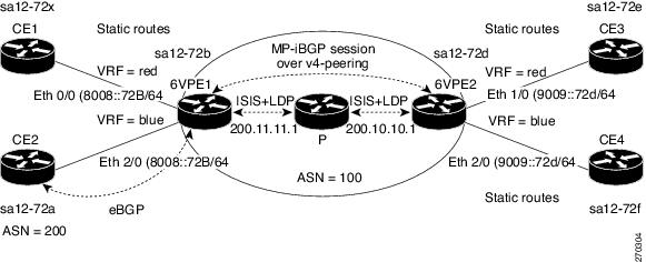
Figure 4-2 illustrates the Example 4-4, which follows the figure.
Figure 4-2 IPv6 VPN over MPLS
Example 4-4 Configuring IPv6 VPN over MPLS
version 12.2no service padservice timestamps debug uptimeservice timestamps log uptimeno service password-encryption!hostname sa14-72b!logging snmp-authfaillogging queue-limit 100!clock timezone GMT 0ip subnet-zeroip cef!ipv6 unicast-routingvrf definition bluerd 200:1address-family ipv6route-target export 200:1route-target import 200:1exit-address-family!vrf definition redrd 100:1address-family ipv6route-target export 100:1route-target import 100:1exit-address-family!ipv6 cefmpls ldp logging neighbor-changesmpls ldp router-id Loopback0!!interface Loopback0ip address 200.11.11.1 255.255.255.255ipv6 address BEEF:11::1/64ipv6 nd prefix default 0 0 off-link no-autoconfigno ipv6 mfib fast!interface Ethernet0/0vrf forwarding redip address 50.1.1.2 255.255.255.0no ip route-cacheno ip mroute-cacheipv6 address 4000::72B/64ipv6 address 8008::72B/64ipv6 nd prefix default infinite infiniteno ipv6 mfib fast!interface Ethernet1/0ip address 40.1.1.2 255.255.255.0ip router isisno ip mroute-cachempls ip!interface Ethernet2/0vrf forwarding blueip address 90.1.1.2 255.255.255.0ipv6 address 8008::72B/64no ipv6 mfib fast!router isisnet 49.0000.0000.0002.00redistribute connected metric 50passive-interface Loopback0!router bgp 100bgp log-neighbor-changesneighbor 200.10.10.1 remote-as 100neighbor 200.10.10.1 update-source Loopback0neighbor 8008::72a remote-as 200!address-family ipv4neighbor 200.10.10.1 activateno auto-summaryno synchronizationexit-address-family!address-family ipv4 multicastno auto-summaryexit-address-family!address-family vpnv6neighbor 200.10.10.1 activateneighbor 200.10.10.1 send-community extendedexit-address-family!address-family ipv6 vrf redno synchronizationredistribute connectedexit-address-family!address-family ipv6 vrf blueneighbor 8008::72a activateno synchronizationredistribute connectedexit-address-family!ip classlessno ip http server!endMonitoring and Maintaining IPv6 VPN over MPLS
For information on monitoring and maintaining IPv6 VPN over MPLS, see the Verifying and Troubleshooting IPv6 VPN section in the Implementing IPv6 VPN over MPLS (6VPE) chapter of the Cisco IOS IPv6 Configuration Guide, Release 12.4T guide at:
Session Limit Per VRF
The session limit Per VRF feature enables you to limit the number of sessions that can be established for VPDN groups associated with a specific VPDN template. Previously, you associated all VPDN groups configured on the router with a single template. By using the session limit Per VRF feature, you can create, define, and name multiple VPDN templates, including a default VPDN template. You can then associate a VPDN group with a specific VPDN template. By configuring a group session limit for a VPDN template, you can limit the maximum number of concurrent sessions allowed for all VPDN groups associated with the VPDN template.
If you configure a group session limit for the default VPDN template (the unnamed VPDN template), that session limit is the same for all VPDN groups not associated with a named VPDN template. If you configure a group session limit that is less than the number of current active sessions, no sessions are terminated and no new sessions can start. For example, if you configure a group session limit of 30 and 50 sessions are active, the router does not terminate any active sessions and it does not allow any new sessions to start.
If a VPDN group is associated with a VPDN template and the VPDN group has a session limit configured, the value of the VPDN group session limit takes precedence over the VPDN template session limit if the VPDN group value is less than the VPDN template value.
You can associate a VPDN group with only one VPDN template at a time. If you associate a VPDN group with a named VPDN template and then with a second VPDN template, the VPDN group is detached from the first VPDN template and associated with the second.
If you attempt to associate a VPDN group with a named VPDN template that you have not configured, the VPDN group uses the system defaults.
The session-limit global configuration command takes precedence over the group session-limit VPDN template configuration command. The session-limit command limits the number of VPDN sessions and the group session-limit command specifies the maximum concurrent sessions allowed across all VPDN groups associated with a particular VPDN template.
The session limit Per VRF feature is described in the following topics:
•
•
•
•
•
•
•
•
Application of VPDN Parameters to VPDN Groups
By default, the router applies VPDN parameters to a VPDN group in the following way:
•
•
•
When you detach a VPDN group from a VPDN template by using the no source vpdn-template command, the router applies VPDN parameters to that VPDN group in the following way:
•
•
VPDN Template Configuration
Not all commands that are available for configuring a VPDN group can be used to configure a VPDN template. For a list of the commands available for VPDN template configuration, see the vpdn-template command reference page in the Session Limit Per VRF, Release 12.2(4)B feature module.
Feature History for Session Limit Per VRF
Restrictions for Session Limit Per VRF
The session limit Per VRF feature has the following restrictions:
•
•
•
•
Prerequisites for Session Limit Per VRF
The session limit Per VRF feature has the following requirements:
•
Configuring Session Limit Per VRF
To configure the session limit Per VRF feature on the Cisco 10000 series router, enter the following commands beginning in global configuration mode:
Verifying a Session Limit Per VRF Configuration
To verify the configuration of the session limit Per VRF feature, enter the following commands in privileged EXEC mode:
Configuration Examples for Session Limit Per VRF
Example 4-5 creates three VPDN groups named group1, group2, and group3. VPDN group1 and group2 are attached to the default VPDN template, which has a session limit of 10. VPDN group1 and group2 can have no more than a combined total of 10 concurrent sessions. For example, if group1 has three sessions, group2 can only have seven sessions.
In Example 4-5, using the session-limit 5 command allows VPDN group1 to have no more than 5 sessions. Using the session-limit 20 command allows VPDN group2 to have no more than 20 sessions. However, as previously indicated, the default VPDN template has a session limit of 10. Therefore, the combined number of sessions for VPDN group1 and group2 cannot exceed 10 sessions. If group1 has 5 sessions, group2 can only have 5 sessions. If group1 does not have any active sessions, group2 can have a maximum of 10 sessions, even though group2 is configured with the session-limit 20 command.
In Example 4-5, VPDN group3 does not have a session limit configured. Using the no source vpdn-template command detaches group3 from the default VPDN template.
Example 4-5 Configuring Session Limit Per VRF
vpdn-templategroup session-limit 10exitvpdn-group group2accept-dialinprotocol anyexitsession-limit 20exitvpdn-group group1accept-dialinprotocol anyexitsession-limit 5vpdn-group group3accept-dialinprotocol anyexitno source vpdn-templateExample 4-6 creates a default VPDN template and three VPDN groups named groupA, groupB, and groupC. As indicated in the default VPDN template configuration, the maximum combined number of sessions allowed for all VPDN groups associated with the default template is 10 sessions. The local name of the default VPDN template is local-name. Example 4-6 also creates an additional VPDN template named templateA, which has a session limit of 50. The combined number of sessions for all VPDN groups associated with templateA cannot exceed 50 concurrent sessions, regardless of the session limits set for the individual VPDN groups. VPDN groupA and groupB are attached to VPDN templateA and each group has an individual session limit of 30 sessions. Because groupA and groupB are attached to VPDN templateA, they use the hostname host1 as their local name.
In Example 4-6, the source vpdn-template command is not used to associate VPDN groupC with a specific VPDN template. Therefore, by default, VPDN groupC is attached to the default VPDN template, which has a group session limit of 10. VPDN groupC inherits the local name local-name from the default VPDN template.
Example 4-6 Configuring Session Limit Per VRF
hostname host1vpdn-templategroup session-limit 10local name local-nameexitvpdn-template templateAgroup session-limit 50exitvpdn-group groupAaccept-dialinprotocol anyexitsource vpdn-template templateAsession-limit 30exitvpdn-group groupBaccept-dialinprotocol anyexitsource vpdn-template templateAsession-limit 30exitvpdn-group groupCaccept-dialinprotocol anyMonitoring and Maintaining Session Limit Per VRF
To monitor and maintain the session limit Per VRF feature, enter the following commands in privileged EXEC mode:
Half-Duplex VRF
The Half-Duplex VRF (HDVRF) feature provides scalable hub and spoke connectivity for subscribers of a multiprotocol label switching-based virtual private network (MPLS VPN) service. These subscribers connect to the provider edge (PE) router of the wholesale service provider, and they use the same or different services (for example, the same or different VRFs). The HDVRF feature prevents local connectivity between subscribers at the spoke PE router and ensures that a hub site provides subscriber connectivity. Any sites that connect to the same PE router must forward intersite traffic using the hub site. This ensures that the routing done at the spoke site is always access side interface to network side interface, or network side interface to access side interface, and never access side to access side.
In hub and spoke topologies in which multiple-spoke customer edge (CE) routers, also referred to as spokes, connect to the same PE router, the PE router locally switches the spokes without passing the traffic through the upstream Internet service provider (ISP). In releases earlier than Cisco IOS Release 12.2(16)BX2, when spokes connect to the same PE router, it was necessary to configure each spoke in a separate VRF to ensure that the traffic between the spokes always traverses the central link between the wholesale service provider and the ISP. However, this solution is manageable only if the number of spokes is relatively small. When a large number of spokes are connected to the same PE router, configuring a single VRF for each spoke can become quite complex and can greatly increase memory usage. This is true especially in large-scale wholesale service provider environments that support high-density remote access to Layer 3 VPNs.
The HDVRF feature addresses the limitations previously imposed on hub and spoke topologies by removing the requirement of one VRF per spoke and ensuring that subscriber traffic always traverses the central link between the wholesale service provider and the ISP, whether the subscriber traffic is being routed to a remote network by way of the upstream ISP or to another locally or remotely connected subscriber.
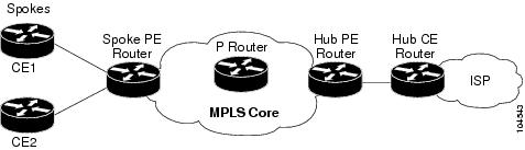
Figure 4-3 shows a sample hub and spoke topology for HDVRF.
Figure 4-3 Hub and Spoke Topology for Half-Duplex VRF
The Half-Duplex VRF feature is described in the following topics:
•
•
•
•
•
•
•
Upstream and Downstream VRFs
HDVRF uses two unidirectional VRFs, called upstream VRF and downstream VRF, to forward IP traffic between the spokes and the hub PE router.
The upstream VRF is used to forward the IP traffic from the spokes toward the MPLS VPN backbone. This VRF typically contains only a default route; but, depending on the configuration, it might also contain such information as summary routes and multiple default routes. The default route points to the interface on the hub PE router that connects to the upstream ISP. The Cisco 10000 series router dynamically learns about the default route from the routing updates that the hub PE router or home gateway sends. The upstream VRF also contains the virtual access interfaces that connect the spokes, but it contains no other local interfaces.
The downstream VRF is used to forward the traffic from the MPLS core back to the spokes. This VRF contains PPP peer routes for the spokes and per-user static routes imported from the authentication, authorization, and accounting (AAA) server. It also contains the routes imported from the hub PE router. These routes are the dynamically allocated virtual access interfaces of the subscribers associated with a particular service.
The Cisco 10000 series router redistributes routes from the downstream VRF into Multiprotocol Border Gateway Protocol (MP-BGP). The spoke PE router typically advertises a summary route across the MPLS core for the connected spokes. The upstream VRF configured on the hub PE router imports the advertised summary route.
Reverse Path Forwarding Check Support
Reverse Path Forwarding (RPF) check ensures that an IP packet entered the router using the correct inbound interface. The HDVRF feature supports unicast RPF check on the spoke-side interfaces. Because different VRFs are used for downstream and upstream forwarding, HDVRF extends the RPF mechanism to ensure that source address checks occur in the downstream VRF.
Feature History for Half-Duplex VRF
Restrictions for Half-Duplex VRF
The Half-Duplex VRF feature has the following restrictions:
•
•
•
Prerequisites for Half-Duplex VRF
The Half-Duplex VRF feature has the following requirements:
•
•
Configuration Tasks for Half-Duplex VRF
To configure the Half-Duplex VRF feature, perform the following configuration tasks:
•
Configuring Upstream and Downstream VRFs on the L2TP Access Concentrator and PE Router
To configure the upstream and downstream VRFs on the PE router, enter the following commands beginning in global configuration mode:
Example 4-7 shows how to configure a downstream VRF named D.
Example 4-7 Configuring the Downstream VRF
Router(config)# ip vrf DRouter(config-vrf)# description Downstream VRF - to subscribersRouter(config-vrf)# rd 1:8Router(config-vrf)# route-target export 1:100Example 4-8 shows how to configure an upstream VRF named U.
Example 4-8 Configuring the Upstream VRF
Router(config)# ip vrf URouter(config-vrf)# description Upstream VRF - to hub PERouter(config-vrf)# rd 1:0Router(config-vrf)# route-target import 1:0Associating VRFs
After you define and configure the VRFs on the PE routers, associate each VRF with:
•
•
The virtual template interface is used to create and configure a virtual access interface (VAI). For information about configuring a virtual template interface, see the "Configuring a Virtual Template Interface" section on page 3-17.
To associate a VRF, enter the following commands on the PE router beginning in interface configuration mode:
Example 4-9 associates the VRF named vpn1 with the Virtual-Template1 interface and specifies the downstream VRF named D.
Example 4-9 Associating a Downstream VRF with a Virtual Template Interface
Router(config)# interface Virtual-Template1Router(config-if)# ip vrf forwarding vpn1 downstream DRouter(config-if)# ip unnumbered Loopback1Router(config-if)# no peer default ip addressRouter(config-if)# ppp authentication chap vpn1Router(config-if)# ppp authorization vpn1Router(config-if)# ppp accounting vpn1Configuring RADIUS
To configure the downstream VRF for an AAA server, enter the following Cisco attribute value:
cisco-avpair = "ip:vrf-id=vrf-name1 downstream vrf-name2"where:
The vrf-name1 argument is the name of the VRF associated with the subinterface or virtual template interface.
The vrf-name2 argument is the name of the downstream VRF into which all of the subscriber routes from the AAA server are installed.
Note
Example 4-10 shows how to configure a downstream VRF named D on a AAA server:
Example 4-10 Configuring the Downstream VRF on RADIUS
cisco-avpair = "ip:vrf-id=U downstream D"Configuration Examples for Half-Duplex VRF
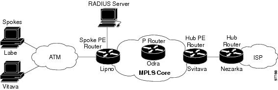
This section provides the following configuration examples. These examples use the hub and spoke topology shown in Figure 4-4.
•
Figure 4-4 Sample Topology for Half-Duplex Configuration
Hub and Spoke Sample Configuration with Half-Duplex VRFs
Example 4-11 shows how to connect two PPPoE clients to a single VRF pair on the spoke PE router named Lipno. Although both PPPoE clients are configured in the same VRF, all communication occurs using the hub PE router. Half-duplex VRFs are configured on the spoke PE. The client configuration is downloaded to the spoke PE from the RADIUS server.
Example 4-11 Configuring the Spoke PE Router
aaa new-model!aaa group server radius Rserver 22.0.20.26 auth-port 1812 acct-port 1813!aaa authentication ppp default group radiusaaa authorization network default group radius!ip vrf Ddescription Downstream VRF - to spokesrd 1:8route-target export 1:100!ip vrf Udescription Upstream VRF - to hubrd 1:0route-target import 1:0!vpdn enable!vpdn-group Uaccept-dialinprotocol pppoevirtual-template 1!interface Loopback0ip address 100.0.0.8 255.255.255.255!interface Loopback2ip unnumbered Loopback2ip vrf forwarding Uip address 2.0.0.8 255.255.255.255!interface ATM2/0pvc 3/100protocol pppoe!pvc 3/101protocol pppoe!interface Virtual-Template1no ip addressppp authentication chap!router bgp 1no synchronizationneighbor 100.0.0.34 remote-as 1neighbor 100.0.0.34 update-source Loopback0no auto-summary!address-family vpnv4neighbor 100.0.0.34 activateneighbor 100.0.0.34 send-community extendedno auto-summaryexit-address-family!address-family ipv4 vrf Uno auto-summaryno synchronizationexit-address-family!address-family ipv4 vrf Dredistribute staticno auto-summaryno synchronizationexit-address-family!ip local pool U-pool 2.8.1.1 2.8.1.100!radius-server host 22.0.20.26 auth-port 1812 acct-port 1813radius-server key ciscoRADIUS Sample Configuration
Example 4-12 shows how to configure the RADIUS server for HDVRF support. In this example, the spokes inherit the default configuration. Static routes per spoke are defined to demonstrate that HDVRF supports per-user static routes. The functionality of the HDVRF feature does not require that you define static routes per spoke. This configuration was tested on FreeRADIUS 0.8.1.
Example 4-12 Configuring RADIUS for Half-Duplex VRFs
DEFAULT Service-Type == Framed-UserFramed-Protocol = PPP,cisco-avpair = "ip:vrf-id=U downstream D",cisco-avpair = "ip:ip-unnumbered=Loopback 2",cisco-avpair = "ip:addr-pool=U-pool",Fall-Through = Yeslabe Auth-Type := Local, User-Password == "labe"cisco-avpair = "ip:route=2.0.0.5 255.255.255.255"vltava Auth-Type := Local, User-Password == "vltava"cisco-avpair = "ip:route=2.0.0.2 255.255.255.255"
Note
Monitoring and Maintaining Half-Duplex VRF
To monitor and maintain upstream and downstream VRFs, enter any of the following commands in privileged EXEC mode:
Example 4-13 shows how to display information about the interface named virtual-access 3.
Example 4-13 show running-config interface—virtual-access 3
Lipno# show running-config interface virtual-access 3Building configuration...Current configuration : 92 bytes!interface Virtual-Access3ip vrf forwarding U downstream Dip unnumbered Loopback2endExample 4-14 shows how to display information about the interface named virtual-access 4.
Example 4-14 show running-config interface—virtual-access 4
Lipno# show running-config interface virtual-access 4Building configuration...Current configuration : 92 bytes!interface Virtual-Access4ip vrf forwarding U downstream Dip unnumbered Loopback2endExample 4-15 shows how to display the routing table for the downstream VRF named D.
Example 4-15 show ip route vrf—Downstream
Lipno# show ip route vrf DRouting Table: DCodes: C - connected, S - static, R - RIP, M - mobile, B - BGPD - EIGRP, EX - EIGRP external, O - OSPF, IA - OSPF inter areaN1 - OSPF NSSA external type 1, N2 - OSPF NSSA external type 2E1 - OSPF external type 1, E2 - OSPF external type 2i - IS-IS, L1 - IS-IS level-1, L2 - IS-IS level-2, ia - IS-IS interarea* - candidate default, U - per-user static route, o - ODRP - periodic downloaded static routeGateway of last resort is not set2.0.0.0/8 is variably subnetted, 5 subnets, 2 masksU 2.0.0.2/32 [1/0] via 2.8.1.1S 2.0.0.0/8 is directly connected, Null0U 2.0.0.5/32 [1/0] via 2.8.1.2C 2.8.1.2/32 is directly connected, Virtual-Access4C 2.8.1.1/32 is directly connected, Virtual-Access3Example 4-16 shows how to display the routing table for the upstream VRF named U.
Example 4-16 show ip route vrf—Upstream
Lipno# show ip route vrf URouting Table: UCodes: C - connected, S - static, R - RIP, M - mobile, B - BGPD - EIGRP, EX - EIGRP external, O - OSPF, IA - OSPF inter areaN1 - OSPF NSSA external type 1, N2 - OSPF NSSA external type 2E1 - OSPF external type 1, E2 - OSPF external type 2i - IS-IS, L1 - IS-IS level-1, L2 - IS-IS level-2, ia - IS-IS interarea* - candidate default, U - per-user static route, o - ODRP - periodic downloaded static routeGateway of last resort is 100.0.0.20 to network 0.0.0.02.0.0.0/32 is subnetted, 1 subnetsC 2.0.0.8 is directly connected, Loopback2B* 0.0.0.0/0 [200/0] via 100.0.0.20, 1w5d