-
Cisco 10000 Series Router Software Configuration Guide
-
About This Guide
-
Broadband Aggregation and Leased-Line Overview
-
Scalability and Performance
-
Configuring Remote Access to MPLS VPN
-
Configuring Multiprotocol Label Switching
-
Configuring the Layer 2 Tunnel Protocol Access Concentrator and Network Server
-
Configuring PPPoE over Ethernet and IEEE 802.1Q VLAN
-
Configuring IP Unnumbered on IEEE 802.1Q VLANs
-
Configuring ATM Permanent Virtual Circuit Autoprovisioning
-
Configuring the Multihop Feature
-
Configuring Address Pools
-
Configuring Local AAA Server, User Database--Domain to VRF
-
Configuring Traffic Filtering
-
Unicast Reverse Path Forwarding
-
Configuring Automatic Protection Switching
-
Configuring IP Multicast
-
Configuring RADIUS Features
-
Cisco 10000 Series Router PXF Stall Monitor
-
SSO - BFD
-
Configuring Link Noise Monitoring
-
Configuring L2 Virtual Private Networks
-
Configuring L2VPN Interworking
-
Configuring Multilink Point-to-Point Protocol Connections
-
Configuring Gigabit EtherChannel Features
-
Configuring IP Version 6
-
Configuring Template ACLs
-
Protecting the Router from DoS Attacks
-
IP Tunneling
-
RADIUS Attributes
-
Glossary
-
 Feedback
Table Of Contents
Configuring Remote Access to MPLS VPN
DHCP Relay Agent Information Option—Option 82
DHCP Relay Support for MPLS VPN Suboptions
Feature History for RA to MPLS VPN
Restrictions for RA to MPLS VPN
Prerequisites for RA to MPLS VPN
Configuration Tasks for RA to MPLS VPN
Configuring the MPLS Core Network
Enabling Label Switching of IP Packets on Interfaces
Configuring Virtual Routing and Forwarding Instances
Configuring Multiprotocol BGP PE to PE Routing Sessions
Configuring Access Protocols and Connections
Configuring a Virtual Template Interface
Configuring PPP over ATM Virtual Connections and Applying Virtual Templates
Configuring PPPoE over ATM Virtual Connections and Applying Virtual Templates
Configuring PPPoE over Ethernet Virtual Connections and Applying Virtual Templates
Configuring RBE over ATM Virtual Connections
Configuring and Associating Virtual Private Networks
Configuring Virtual Private Networks
Associating VPNs with a Virtual Template Interface
Configuring RADIUS User Profiles for RADIUS-Based AAA
Configuration Examples for RA to MPLS VPN
PPPoA to MPLS VPN Configuration Example
PPPoE to MPLS VPN Configuration Example
RBE to MPLS VPN Configuration Example
Monitoring and Maintaining an MPLS Configuration
Verifying the Routing Protocol Is Running
Verifying Connections Between Neighbors
Monitoring and Maintaining the MPLS VPN
Verifying the PE to PE Routing Protocols
Verifying the PE to CE Routing Protocol
Monitoring and Maintaining PPPoX to MPLS VPN
Monitoring and Maintaining RBE to MPLS VPN
Configuring Remote Access to MPLS VPN
TheCisco 10000 series router supports the IP virtual private network (VPN) feature for Multiprotocol Label Switching (MPLS). MPLS-based VPNs allow service providers to deploy a scalable and cost-effective VPN service that provides a stable and secure path through the network. An enterprise or Internet service provider (ISP) can connect to geographically dispersed sites through the service provider's network. Using the MPLS backbone, a set of sites are interconnected to create an MPLS VPN.
The remote access (RA) to MPLS VPN feature on the Cisco 10000 series router allows the service provider to offer a scalable end-to-end VPN service to remote users. The RA to MPLS VPN feature integrates the MPLS-enabled backbone with broadband access capabilities. By integrating access VPNs with MPLS VPNs, a service provider can:
•
Enable remote users and offices to seamlessly access their corporate networks
•
•
•
•
The RA to MPLS VPN feature is described in the following topics:
•
•
•
•
•
•
•
•
•
MPLS VPN Architecture
The MPLS VPN architecture enables the service provider to build the MPLS VPN network one time and add VPNs for new customers as needed, including them in the already established network. The elements that comprise the MPLS VPN are:
•
•
•
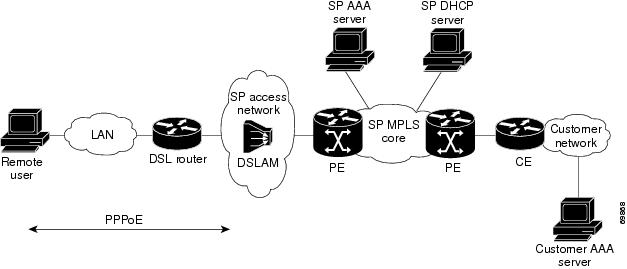
Figure 3-1 shows an example of the MPLS VPN architecture.
Figure 3-1 MPLS VPN Network—Example
Access Technologies
The Cisco 10000 series router supports routed bridge encapsulation (RBE) protocol. Point-to-point protocol (PPP) access-based permanent virtual circuits (PVCs) is supported by using the following PPP access encapsulation methods:
•
•
By using these PPP access technologies, the Cisco 10000 series router can terminate up to 32,000 sessions and support many features, including:
•
•
•
Note
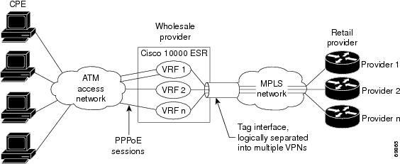
Figure 3-2 shows the topology of an integrated PPPoX (PPPoE or PPPoA) access to a multiprotocol label switching virtual private network (MPLS VPN) solution.
Figure 3-2 PPPoX Access to MPLS VPN Topology
In the figure, the service provider operates an MPLS VPN that interconnects all customer sites. The service provider's core network is an MPLS backbone with VPN service capability. The service provider provides all remote access operations to its customer. The network side interfaces are tagged interfaces, logically separated into multiple VPNs.
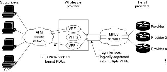
Figure 3-3 shows the topology of an RBE to MPLS VPN solution.
Figure 3-3 RBE to MPLS VPN Topology
In the figure, the wholesale provider uses VPNs to separate the subscribers of different retail providers. The subscribers are uniquely placed in VRFs on the access side. A tag interface separates traffic for the different retail providers on the network side. The MPLS VPN technology is used to assign tags in a VPN-aware manner.
PPP over ATM to MPLS VPN
The Cisco 10000 series router supports a PPP over ATM (PPPoA) connection to an MPLS VPN architecture. In this model, when a remote user attempts to establish a connection with a corporate network, a PPPoA session is initiated and is terminated on the service provider's virtual home gateway (VHG) or provider edge (PE) router. All remote hosts connected to a particular CE router must be part of the same VPN to which the CE router is connected.
The following events occur when the remote user attempts to access the corporate network or ISP:
1.
2.
3.
a.
b.
c.
Typically, the customer RADIUS server is located within the customer VPN. To ensure that transactions between the VHG/PE router and the customer RADIUS server occur over routes within the customer VPN, the VHG/PE router is assigned at least one IP address that is valid within the VPN.
4.
5.
•
•
•
6.
Use virtual template interfaces to map sessions to VRFs. The Cisco 10000 series router can then scale to 32,000 sessions. In Cisco IOS Release 12.2(16)BX1 and later releases, when you map sessions to VRFs by using the RADIUS server, use the syntax ip:vrf-id or ip:ip-unnumbered. These vendor specific attributes (VSAs) enhance the scalability of per-user configurations because a new full virtual access interface is not required. For more information, see the "Enhancing Scalability of Per-User Configurations" section on page 2-17.
Note
PPP over Ethernet to MPLS VPN
The Cisco 10000 series router supports a PPP over Ethernet (PPPoE) connection to an MPLS VPN architecture. In this model, when a remote user attempts to establish a connection with a corporate network, a PPPoE session is initiated and is terminated on the service provider's virtual home gateway (VHG) or provider edge (PE) router. All remote hosts connected to a particular CE router must be part of the VPN to which the CE router is connected.
The PPPoE to MPLS VPN architecture is a flexible architecture with the following characteristics:
•
•
•
Use virtual template interfaces to map sessions to VRFs. The Cisco 10000 series router can then scale to 32,000 sessions. In Cisco IOS Release 12.2(16)BX1 and later releases, when you map sessions to VRFs by using the RADIUS server, use the syntax ip:vrf-id or ip:ip-unnumbered. These vendor specific attributes (VSAs) enhance the scalability of per-user configurations because a new full virtual access interface is not required. For more information, see the "Enhancing Scalability of Per-User Configurations" section on page 2-17.
Note
The following events occur as the VHG or PE router processes the incoming PPPoE session:
1.
2.
3.
a.
b.
c.
Use virtual template interfaces to map sessions to VRFs. The Cisco 10000 series router can then scale to 32,000 sessions. In Cisco IOS Release 12.2(16)BX1 and later releases, when you map sessions to VRFs by using the RADIUS server, use the syntax ip:vrf-id or ip:ip-unnumbered. These vendor specific attributes (VSAs) enhance the scalability of per-user configurations because a new full virtual access interface is not required. For more information, see the "Enhancing Scalability of Per-User Configurations" section on page 2-17.
Note
Typically, the customer RADIUS server is located within the customer VPN. To ensure that transactions between the VHG/PE router and the customer RADIUS server occur over routes within the customer VPN, the VHG/PE router is assigned at least one IP address that is valid within the VPN.
4.
5.
•
•
•
6.
RBE over ATM to MPLS VPN
The Cisco 10000 series router supports an ATM RBE to MPLS VPN connection. RBE is used to route IP over bridged RFC 1483 Ethernet traffic from a stub-bridged LAN. The ATM connection appears like a routed connection; however, the packets received on the interface are bridged IP packets. RBE looks at the IP header of the packets arriving at an ATM interface and routes the packets instead of bridging them.
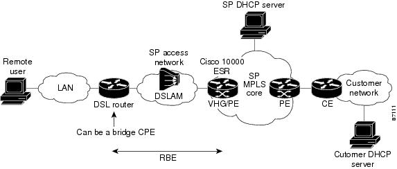
In Figure 3-4, RBE is configured between the DSL router and the Cisco 10000 series router, acting as the VHG/PE router.
Figure 3-4 DSL RBE to MPLS VPN Integration
The DSL router can be set up as a pure bridge or it can be set up for integrated routing and bridging (IRB) where multiple LAN interfaces are bridged through the bridge group virtual interface (BVI). Each of the DSL routers terminates on a separate point-to-point subinterface on the VHG/PE, which is statically configured with a specific VRF. Remote user authentication or authorization is available with Option 82 for DSL RBE remote access. RBE treats the VHG/PE subinterface as if it is connected to an Ethernet LAN, but avoids the disadvantages of pure bridging, such as broadcast storms, IP hijacking, and ARP spoofing issues. Address management options include static and VRF-aware DHCP servers.
Note
http://www.cisco.com/univercd/cc/td/doc/product/vpn/solution/rampls2/ovprov/ra_op_05.htm
MPLS VPN ID
The MPLS VPN ID is a 14-digit hexadecimal number that uniquely identifies a VPN and its associated VRF across all VHGs and PE routers in the network. In a router with multiple VPNs configured, you can use a VPN ID to identify a particular VPN. The VPN ID follows a standard specification (RFC 2685). The configuration of a VPN ID is optional.
You can configure a VRF instance for each VPN configured on the Cisco 10000 series router. By using the vpn id VRF configuration command, you can assign a VPN ID to a VPN. The router stores the VPN ID in the corresponding VRF structure for the VPN (see the "Configuring Virtual Routing and Forwarding Instances" section).
Note
DHCP servers use the VPN ID to identify a VPN and allocate resources as the following describes:
1.
2.
3.
4.
5.
The RADIUS server uses the VPN ID to assign dialin users to the proper VPN. Typically, a user login consists of the following packets:
•
•
Note
http://www.cisco.com/en/US/docs/ios/12_2/12_2b/12_2b4/feature/guide/12b_vpn.html
DHCP Relay Agent Information Option—Option 82
The Cisco 10000 series router supports the Dynamic Host Configuration Protocol (DHCP) relay agent information option (Option 82) feature when ATM routed bridge encapsulation (RBE) is used to configure DSL access. This feature communicates information to the DHCP server by using a suboption of the DHCP relay agent information option called agent remote ID. The information sent in the agent remote ID includes an IP address identifying the relay agent, information about the ATM interface, and information about the PVC over which the DHCP request came in. The DHCP server can use this information to make IP address assignments and security policy decisions.
Acting as the DHCP relay agent, the Cisco 10000 series router can also include VPN ID information in the agent remote ID suboption when forwarding client-originated DHCP packets to a DHCP server that has knowledge of existing VPNs. The VPN-aware DHCP server receives the DHCP packets and uses the VPN ID information to determine from which VPN to allocate an address. The DHCP server responds to the DHCP relay agent and includes information that identifies the originating client.
Note
DHCP Relay Support for MPLS VPN Suboptions
The DHCP relay agent information option (Option 82) enables a Dynamic Host Configuration Protocol (DHCP) relay agent to include information about itself when forwarding client-originated DHCP packets to a DHCP server. In some environments, the relay agent has access to one or more MPLS VPNs. A DHCP server that wants to offer service to DHCP clients on those different VPNs needs to know the VPN where each client resides. The relay agent typically knows about the VPN association of the DHCP client and includes this information in the relay agent information option.
The DHCP relay support for MPLS VPN suboptions feature allows the Cisco 10000 series router, acting as the DHCP relay agent, to forward VPN-related information to the DHCP server by using the following three suboptions of the DHCP relay agent information option:
•
•
•
The DHCP relay agent uses the VPN identifier suboption to tell the DHCP server the VPN for each DHCP request that it passes on to the DHCP server, and also uses the suboption to properly forward any DHCP reply that the DHCP server sends back to the relay agent. The VPN identifier suboption contains the VPN ID configured on the incoming interface to which the client is connected. If you configure the VRF name but not the VPN ID, the VRF name is used as the VPN identifier suboption. If the interface is in global routing space, the router does not add the VPN suboptions.
The subnet selection suboption allows the separation of the subnet where the client resides from the IP address that is used to communicate with the relay agent. In some situations, the relay agent needs to specify the subnet on which a DHCP client resides that is different from the IP address the DHCP server can use to communicate with the relay agent. The DHCP relay agent includes the subnet selection suboption in the relay agent information option, which the relay agent passes on to the DHCP server.
The server identifier override suboption contains the incoming interface IP address, which is the IP address on the relay agent that is accessible from the client. By using this information, the DHCP client sends all renew and release packets to the relay agent. The relay agent adds all the VPN suboptions and then forwards the renew and release packets to the original DHCP server.
After adding these suboptions to the DHCP relay agent information option, the gateway address changes to the relay agent's outgoing interface on the DHCP server side. The DHCP server uses this gateway address to send reply packets back to the relay agent. The relay agent then removes the relay agent information options and forwards the packets to the DHCP client on the correct VPN.
Note
http://www.cisco.com/en/US/docs/ios/12_2/12_2b/12_2b4/feature/guide/12b_dhc.html
Feature History for RA to MPLS VPN
Restrictions for RA to MPLS VPN
The RA to MPLS VPN feature has the following restrictions:
•
•
•
•
Prerequisites for RA to MPLS VPN
The RA to MPLS VPN feature has the following requirements:
•
–
–
–
–
Note
•
•
•
•
Configuration Tasks for RA to MPLS VPN
To configure the RA to MPLS VPN feature, perform the following configuration tasks:
•
•
•
•
Configuring the MPLS Core Network
To configure an MPLS core network, perform the following tasks:
•
•
•
Enabling Label Switching of IP Packets on Interfaces
Enable label switching of IP packets on each PE router interface on the MPLS side of the network. The Cisco 10000 series router MPLS network side interface is a tagged interface. The packets passing through the interface are tagged packets.
Note
To enable label switching of IP packets on interfaces, enter the following command in interface configuration mode:
Note
Configuring Virtual Routing and Forwarding Instances
Configure VRF instances on each PE router in the provider network. Create one VRF for each VPN connected using the ip vrf command in global configuration mode or router configuration mode.
To create the VRF, do the following:
•
•
To configure a VRF, enter the following commands on the PE router beginning in global configuration mode:
Associating VRFs
After you define and configure the VRFs on the PE routers, associate each VRF with:
•
•
The virtual template interface is used to create and configure a virtual access interface (VAI). For information about configuring a virtual template interface, see the "Configuring a Virtual Template Interface" section.
To associate a VRF, enter the following commands on the PE router beginning in interface configuration mode:
Note
Example 3-1 Associating a VRF with an Interface
interface GigabitEthernet7/0/0.1encapsulation dot1Q 11ip vrf forwarding vpn1ip address 192.168.1.1 255.255.255.0!Example 3-2 Associating a VRF with a Virtual Template Interface
interface Virtual-Template1ip vrf forwarding vpn1ip unnumbered Loopback1no peer default ip addressppp authentication chap vpn1ppp authorization vpn1ppp accounting vpn1Configuring Multiprotocol BGP PE to PE Routing Sessions
To configure multiprotocol BGP (MP-BGP) routing sessions between the PE routers, enter the following commands on the PE routers beginning in global configuration mode:
Example 3-3 Configuring MP-BGP
router bgp 100no synchronizationno bgp default ipv4-unicastbgp log-neighbor-changesneighbor 10.1.1.4 remote-as 100neighbor 10.1.1.4 update-source Loopback0neighbor 10.1.1.4 activateneighbor 10.3.1.4 remote-as 100neighbor 10.3.1.4 update-source Loopback0neighbor 10.3.1.4 activateno auto-summary!address-family ipv4 vrf vrf-1redistribute connectedno auto-summaryno synchronizationexit-address-family!address-family vpnv4neighbor 10.1.1.4 activateneighbor 10.1.1.4 send-community bothneighbor 10.3.1.4 activateneighbor 10.3.1.4 send-community bothexit-address-family!
Note
Configuring Access Protocols and Connections
The Cisco 10000 series router supports the following access protocols:
•
•
•
When a remote user initiates a PPPoA or PPPoE session to the Cisco 10000 series router, a predefined configuration template is used to configure a virtual interface known as a virtual access interface (VAI). The VAI is created and configured dynamically by using a virtual template interface. When the user terminates the session, the VAI goes down and the resources are freed for other client uses.
Note
The virtual template interface is a logical entity that the Cisco 10000 series router applies dynamically as needed to a connection. It is a configuration for an interface, but it is not tied to the physical interface. The VAI uses the attributes of the virtual template to create the session, which results in a VAI that is uniquely configured for a specific user.
After you configure a virtual template, configure the virtual connection that will use the template and then apply the template to the connection. The order in which you create virtual templates and configure the virtual connections that use the templates is not important. However, both the virtual templates and connections must exist before a remote user initiates a session to the Cisco 10000 series router.
The following sections describe how to create a virtual template and apply it to a VAI. For more information, see the "Configuring Virtual Template Interfaces" chapter in the Cisco IOS Dial Technologies Configuration Guide, Release 12.2.
Note
To configure access protocols and connections, perform the following configuration tasks. The first task listed is required and you can perform any of the remaining tasks as needed:
•
•
•
•
•
Configuring a Virtual Template Interface
To create and configure a virtual template interface, enter the following commands beginning in global configuration mode:
Example 3-4 Configuring a Virtual Template Interface
interface virtual-template 1ip unnumbered Loopback1no peer default ip addressppp authentication chap vpn1ppp ipcp ip address requiredppp authorization vpn1ppp accounting vpn1Monitoring and Maintaining a Virtual Access Interface
When a virtual template interface is applied dynamically to an incoming user session, a virtual access interface (VAI) is created. You cannot use the command line interface (CLI) to directly create or configure a VAI, but you can display and clear the VAI by using the following commands in privileged EXEC mode:
Example 3-5 Displaying the Active VAI Configuration
Router# show interfaces virtual-access 1.1 configuration!interface virtual-access1.1ip vrf forwarding vrf-1ip unnumbered Loopback1no ip proxy-arppeer default ip address pool vrf-1ppp authentication chapend
Note
Example 3-6 Clearing Live Sessions
Router# clear interface virtual-access 1.1Router#Configuring PPP over ATM Virtual Connections and Applying Virtual Templates
To configure a range of PVC connections and apply a virtual template interface to them, perform the following configuration task:
•
Note
Configuring Encapsulated PPP over ATM Permanent Virtual Circuits
Configure ATM permanent virtual circuits (PVCs) for encapsulated PPP over ATM on either point-to-point or multipoint subinterfaces. Using point-to-multipoint PVCs significantly increases the maximum number of PPPoA sessions that you can run on the Cisco 10000 series router.
To configure a PVC range with encapsulated PPPoA, enter the following commands beginning in global configuration mode:
Configuring PPPoE over ATM Virtual Connections and Applying Virtual Templates
To configure PPPoE over ATM, perform the following configuration tasks:
•
•
•
•
Note
Configuring a VPDN Group for PPPoE over ATM
To configure the physical interface that will carry the PPPoE session and link it to the appropriate virtual template interface, enter the following commands beginning in global configuration mode:
Configuring PPPoE on ATM Permanent Virtual Circuits
To configure PPPoE on a range of ATM PVCs, enter the following commands beginning in global configuration mode:
Configuring PPPoE on ATM PVCs Using a Different MAC Address
To change the way PPPoE selects a MAC address when PPPoE and RBE are configured on two separate PVCs on the same DSL line, enter the following commands beginning in global configuration mode:
Note
Configuring PPPoE over Ethernet Virtual Connections and Applying Virtual Templates
To configure PPPoE over Ethernet, perform the following configuration tasks:
•
•
Configuring PPPoE over Ethernet in a BBA Group
Note
To configure a broadband aggregation (BBA) group for PPPoE and to link it to the appropriate virtual template interface, enter the following commands beginning in global configuration mode:
Note
Configuring RBE over ATM Virtual Connections
To configure RBE over ATM virtual connections and apply virtual templates, perform the following configuration tasks:
•
•
Configuring the PE Router
To configure the PE router, perform the following required configuration tasks:
•
•
Note
Defining Loopbacks
To define loopbacks, enter the following commands beginning in global configuration mode:
Defining PVCs
To define PVCs, enter the following commands beginning in global configuration mode:
Configuring Label Switching
To configure label switching on the interface connected to the MPLS cloud, enter the following commands beginning in global configuration mode:
Configuring the VRF for Each VPN
To configure the VRF for each VPN, enter the following commands beginning in global configuration mode:
Configuring a Dedicated PVC
To configure a dedicated PVC for each VPN, enter the following commands beginning in global configuration mode:
Configuring BGP to Advertise Networks
To configure BGP to advertise the networks for each VPN, enter the following commands beginning in global configuration mode:
Configuring DHCP Option 82 for RBE
To configure DHCP Option 82 support for RBE connections, enter the following commands beginning in global configuration mode:
Example 3-7 enables DHCP option 82 support on the DHCP relay agent by using the ip dhcp relay information option command. The rbe nasip command configures the router to forward the IP address for Loopback0 to the DHCP server. The value (in hexadecimal) of the agent remote ID suboption is 010100000B0101814058320 and the value of each field is the following:
•
•
•
•
•
–
–
–
Example 3-7 Configuring Option 82 for RBE
ip dhcp-server 172.16.1.2!ip dhcp relay information option!interface Loopback0ip address 11.1.1.129 255.255.255.192!interface ATM4/0no ip address!interface ATM4/0.1 point-to-pointip unnumbered Loopback0ip helper-address 172.16.1.2atm route-bridged ippvc 88/800encapsulation aal5snap!interface Ethernet 5/1ip address 172.16.1.1 255.255.0.0!router eigrp 100network 10.0.0.0network 172.16.0.0!rbe nasip Loopback0Configuring DHCP Relay Support for MPLS VPN Suboptions
To configure DHCP relay support for MPLS VPN suboptions, enter the following commands beginning in global configuration mode:
In Example 3-8, the DHCP relay receives a DHCP request on Ethernet interface 0/1 and sends the request to the DHCP server located at IP helper address 10.44.23.7, which is associated with the VRF named red.
Example 3-8 Configuring DHCP Relay Support for MPLS VPN Suboptions
ip dhcp relay information option vpn!interface ethernet 0/1ip helper-address vrf red 10.44.23.7!Specifying a VPN ID
To specify a VPN ID, enter the following commands beginning in global configuration mode:
Example 3-9 assigns a VPN ID to the VRF named vpn1.
Example 3-9 Configuring a VPN ID
Router(config)# ip vrf vpn1Router(config-vrf)# vpn id al:3f6cRouter(config-vrf)# endConfiguring and Associating Virtual Private Networks
To add a virtual private network (VPN) service to your MPLS configuration, you perform the following tasks:
•
•
Configuring Virtual Private Networks
To configure dial-in and dial-out virtual private networks (VPNs), perform the following tasks:
•
•
For more information about configuring virtual private networks, see the "Configuring Virtual Private Networks" chapter in the Cisco IOS Dial Technologies Configuration Guide, Release 12.2. This chapter describes the procedures used to configure, verify, monitor, and troubleshoot VPNs and also provides configuration examples.
Associating VPNs with a Virtual Template Interface
After you configure the VPNs, associate each one with a virtual template interface. To do this association, perform the following tasks:
•
•
Note
Creating a VRF Configuration for a VPN
To create a VRF configuration for a VPN, enter the following commands beginning in global configuration mode:
Example 3-10 Creating a VRF Configuration for a VPN
ip vrf commonrd 100:1000vpn id 100:1000route-target export 100:1000route-target import 100:1000
Note
Associating a VRF Configuration for a VPN with a Virtual Template Interface
After you create a VRF configuration for a VPN, associate the VRF with a virtual template interface. The virtual template interface is used to create and configure a virtual access interface (VAI).
To associate a VRF, enter the following commands beginning in global configuration mode:
Example 3-11 Associating a VRF Configuration for a VPN with a Virtual Template Interface
interface Virtual-Template1ip vrf forwarding commonip unnumbered Loopback1
Note
•
Configuring RADIUS User Profiles for RADIUS-Based AAA
Use the per VRF AAA feature to partition authentication, authorization, and accounting (AAA) services based on a virtual routing and forwarding (VRF) instance. This feature allows the Cisco 10000 router to communicate directly with the customer RADIUS server without having to go through a RADIUS proxy.
For more information about configuring the per VRF AAA feature on the Cisco 10000 series router, see the "Optional Configuration Tasks for LAC" section on page 5-7.
For more information about configuring your RADIUS server, see your RADIUS documentation.
Verifying VPN Operation
To verify VPN operation, enter any of the following commands in privileged EXEC mode:
Configuration Examples for RA to MPLS VPN
This section provides configuration examples for the following configurations:
•
•
•
PPPoA to MPLS VPN Configuration Example
Example 3-12 shows how to configure the RA to MPLS VPN feature on the Cisco 10000 series router. In this example, one VRF is configured with 300 PPPoA sessions.
Example 3-12 Configuring PPPoA to MPLS VPN
!Enables the AAA access control model.aaa new-model!!Configures AAA accounting.aaa authentication login default noneaaa authentication ppp default localaaa authorization network default localaaa session-id commonenable password vermont!username vpn1 password 0 vpn1!!Configures the vpn1 VRF.ip vrf vpn1rd 10:1route-target export 10:1route-target import 10:1!!Configures the policy map for the default class.policy-map mypolicyclass class-defaultpolice 200000 400000 800000 conform-action transmit exceed-action drop!no virtual-template snmp!!Sets the size of the small and middle buffers.buffers small permanent 20000buffers middle permanent 7000!!Defines the general loopback interface used for reachability to the router and as a!source IP address for sessions (IBGP, TDP, and so on).interface Loopback0ip address 10.1.1.1 255.255.255.255!!Creates a loopback interface in the vpn1 VRF. You do this for each customer VRF you IP!unnumber interfaces to.interface Loopback1ip vrf forwarding vpn1ip address 10.16.1.1 255.255.255.255!!Configures the management interface. You should not configure VPN over the FastEthernet!interface.interface FastEthernet0/0/0ip address 192.168.16.1 255.255.255.0no ip proxy-arp!!Enables label switching of IP packets on the interface.interface GigabitEthernet1/0/0ip address 172.16.4.1 255.255.0.0negotiation autotag-switching ip!interface GigabitEthernet2/0/0ip address 172.16.3.1 255.255.0.0negotiation autotag-switching ip!interface ATM3/0/0no ip addressatm flag s1s0 0atm sonet stm-4no atm ilmi-keepalive!interface ATM4/0/0no ip addressload-interval 30no atm pxf queuingatm sonet stm-4no atm ilmi-keepalive!interface ATM4/0/0.1 multipointrange pvc 3/32 3/354encapsulation aa5mux ppp Virtual-Template1!interface ATM6/0/0no ip addressno atm pxf queuingno atm ilmi-keepalive!interface atm6/0/1no ip addressno atm ilmi-keepalive!interface ATM6/0/2no ip addressno atm ilmi-keepalive!interface ATM6/0/3no ip addressno atm ilmi-keepalive!!Enables label switching of IP packets on the interface.interface POS7/0/0ip address 172.16.1.1 255.255.0.0keepalive 30tag-switching ipcrc32!interface POS8/0/0ip address 172.16.2.1 255.255.0.0keepalive 30tag-switching ipcrc32!!Configures the virtual template and associates the vpn1 VRF with it.interface Virtual-Template1ip vrf forwarding vpn1ip unnumbered Loopback1peer default ip address pool vpn1ppp max-configure 255ppp max-failure 255ppp authentication chapppp timeout retry 25ppp timeout authentication 20!!Configures OSPF to advertise networks.router ospf 200log-adjacency-changesauto-cost reference-bandwidth 10000network 10.1.1.1 0.0.0.0 area 40network 172.16.0.0 0.255.255.255 area 40!!Configures BGP to advertise the networks for each VPN.router bgp 100bgp router-id 10.1.1.1no bgp default ipv4-unicastbgp cluster-id 671154433bgp log-neighbor-changesbgp bestpath scan-time 30bgp scan-time 30neighbor 10.1.1.4 remote-as 100neighbor 10.1.1.4 update-source Loopback0neighbor 10.1.1.4 activate!!Enters address family configuration mode to configure the VRF routing table on BGP.address-family ipv4 vrf vpn1redistribute connectedno auto-summaryno synchronizationexit-address-family!!Configures MP-IBGP.address-family vpnv4neighbor 10.1.1.4 activateneighbor 10.1.1.4 send-community bothexit-address-family!!Specifies the IP local pool to use for the vpn1 VRF address assignment.ip local pool vpn1 192.168.1.1 192.168.2.67!!Enters routing information in the routing table.ip classlessip route 192.168.16.0 255.255.255.0 198.168.76.1no ip http serverip pim bidir-enable!!no cdp run!Configures RADIUS accounting. radius-server retransmit is on by default and cannot be removed.radius-server retransmit 3radius-server authorization permit missing Service-Typecall admission limit 90!PPPoE to MPLS VPN Configuration Example
Example 3-13shows how to configure the RA to MPLS VPN feature with one VRF for PPPoE sessions.
Example 3-13 Configuring PPPoE to MPLS VPN
!!Enables the AAA access control model.aaa new-model!!Configures AAA accounting.aaa authentication login default noneaaa authentication enable default noneaaa authentication ppp default group radiusaaa authorization config-commandsaaa authorization network default localaaa session-id commonenable password cisco!username pppoe password 0 pppoeusername pppoa password 0 pppoausername common password 0 common!!Preprovisions slots in the Cisco 10000 series router for line cards.card 1/0 1gigethernet-1card 2/0 1gigethernet-1card 3/0 1oc12pos-1card 4/0 1oc12pos-1card 5/0 1oc12atm-1card 6/0 1oc12atm-1card 7/0 4oc3atm-1card 8/0 4oc3atm-1!!Creates the common VRF.ip vrf commonrd 100:1000route-target export 100:1000route-target import 100:1000!!Specifies the VPDN group to be used to establish PPPoE sessions and specifies the maximum!number of PPPoE sessions to be established over a virtual circuit.vpdn-group pppoeaccept-dialinprotocol pppoevirtual-template 1pppoe limit per-mac 32000pppoe limit per-vc 1!no virtual-template snmp!!Configures the small buffer.buffers small permanent 15000!vc-class atm vpnprotocol pppoeencapsulation aal5snap!!Defines the general loopback interface used for reachability to the router and as a!source IP address for sessions (IBGP, TDP, and so on).interface Loopback0ip address 10.16.3.1 255.255.255.255ip ospf network point-to-point!!Creates a loopback interface in the vpn1 VRF. You do this for each customer VRF you IP!unnumber interfaces to.interface Loopback1ip vrf forwarding vpn1ip address 10.24.1.1 255.255.255.255!interface Loopback2ip vrf forwarding vpn2ip address 10.8.1.2 255.255.255.255!!Configures the management interface. You should not configure VPN over the FastEthernet!interface.interface FastEthernet0/0/0ip address 10.9.100.32 255.0.0.0no ip proxy-arpfull-duplex!!Enables label switching of IP packets on the interface.interface GigabitEthernet1/0/0ip address 10.1.10.1 255.255.0.0no ip redirectsload-interval 30negotiation autotag-switching ip!interface GigabitEthernet2/0/0ip address 10.2.10.1 255.255.0.0no ip redirectsload-interval 30negotiation autotag-switching ip!interface POS3/0/0ip address 10.3.10.1 255.255.0.0no ip redirectsip ospf cost 2keepalive 30tag-switching ipcrc 32clock source internalpos scramble-atm!interface POS4/0/0ip address 10.4.10.1 255.255.0.0no ip redirectsip ospf cost 2keepalive 30tag-switching ipcrc 32clock source internalpos scramble-atm!interface ATM5/0/0no ip addressload-interval 30no atm pxf queuingatm clock INTERNALatm sonet stm-4no atm ilmi-keepalive!interface ATM5/0/0.1000 multipointrange pvc 2/32 2/63!class-int vpn!interface ATM6/0/0no ip addressload-interval 30no atm pxf queuingatm clock INTERNALatm sonet stm-4no atm ilmi-keepalive!interface ATM6/0/0.1000 multipointrange pvc 2/32 2/63encapsulation aal5snapprotocol pppoe!class-int vpn!interface ATM7/0/0no ip addressno atm ilmi-keepalive!interface ATM7/0/1no ip addressno atm ilmi-keepalive!interface ATM7/0/2no ip addressno atm ilmi-keepalive!interface ATM7/0/3no ip addressno atm ilmi-keepalive!interface ATM8/0/0no ip addressno atm ilmi-keepalive!interface ATM8/0/1no ip addressno atm ilmi-keepalive!interface ATM8/0/2no ip addressno atm ilmi-keepalive!interface ATM8/0/3no ip addressno atm ilmi-keepalive!interface ATM8/0/3.100 multipointrange pvc 2/32 2/42encapsulation aal5snapprotocol pppoe!!Associates the common VRF with the interface.interface ATM8/0/3.101 point-to-pointip vrf forwarding commonip address 10.22.10.1 255.255.255.0pvc 3/32encapsulation aal5snap!!Defines the virtual template and associates the common VRF with it.interface Virtual-Template1ip vrf forwarding commonip unnumbered Loopback1peer default ip address pool commonppp authentication chap!!Configures OSPF to advertise the networks.router ospf 100log-adjacency-changesauto-cost reference-bandwidth 1000network 10.16.3.1 0.0.0.0 area 0network 10.1.0.0 0.0.255.255 area 0network 10.2.0.0 0.0.255.255 area 0network 10.3.0.0 0.0.255.255 area 0network 10.4.0.0 0.0.255.255 area 0!router ripversion 2!!Enters address family configuration mode to configure the VRF for PE to CE routing!sessions.address-family ipv4 vrf commonversion 2network 10.0.0.0no auto-summaryexit-address-family!!Configures BGP to advertise the networks for the VPN.router bgp 100no synchronizationno bgp default ipv4-unicastbgp log-neighbor-changesneighbor 172.16.1.4 remote-as 100neighbor 172.16.1.4 activate!!Enters address family configuration mode to configure the common VRF for PE to CE routing!sessions.address-family ipv4 vrf commonno auto-summaryno synchronizationaggregate-address 2.10.0.0 255.255.0.0 summary-onlyexit-address-family!address-family vpnv4neighbor 172.16.1.4 activateneighbor 172.16.1.4 send-community bothexit-address-family!!Specifies the IP local pool to use for the VRF address assignment.ip local pool common 2.10.1.1 2.10.126.0ip classless!Enters routing information in the routing table for the VRF.ip route 20.0.0.0 255.0.0.0 FastEthernet0/0/0 20.9.0.1ip route vrf common 10.22.0.0 255.255.0.0 Null0ip route vrf common 10.30.0.0 255.255.0.0 2.1.1.1 3ip route vrf common 10.32.0.0 255.255.0.0 2.2.151.1 2ip route vrf common 10.33.0.0 255.255.0.0 2.3.101.1 2no ip http serverip pim bidir-enable!no cdp run!!Specifies the RADIUS host and configures RADIUS accounting. radius-server retransmit is!on by default and cannot be removed.radius-server host 10.19.100.150 auth-port 1645 acct-port 1646radius-server retransmit 3radius-server key testradius-server authorization permit missing Service-Typeradius-server vsa send authenticationcall admission limit 90!RBE to MPLS VPN Configuration Example
Example 3-14 shows how to configure RBE on ATM interfaces, creates and associates two VRFs named CustomerA and CustomerB, and configures DHCP Option 82 support for RBE connections.
Example 3-14 Configuring RBE to MPLS VPN
ip vrf CustomerArd 100:100route-target export 100:100route-target import 100:100!ip vrf CustomerBrd 101:101route-target export 101:101route-target import 101:101!interface int g1/0/0ip address 192.168.1.1 255.255.255.0tag-switching ip!interface loopback0! BGP update sourceip address 10.100.10.1 255.255.255.255!router ospf 1network 192.168.1.0 0.0.0.255 area 0redistribute connected!interface loopback 1! description for VRF CustomerAip address 10.101.10.1 255.255.255.255ip vrf forwarding CustomerA!interface loopback 2! description for VRF CustomerBip address 10.102.20.1 255.255.255.255ip vrf forwarding CustomerB!ip dhcp relay information optionip dhcp relay information option vpn!interface atm7/0/0no atm pxf queuing!interface atm7/0/0.1 point-to-pointip vrf forwarding CustomerAip unnumbered loopback1ip helper-address vrf CustomerA 192.168.2.1atm route iprange pvc 101/32 101/2031encapsulation aal5snap!interface atm8/0/0no atm pxf queuing!interface atm8/0/0.1 point-to-pointip vrf forwarding CustomerBip unnumbered loopback2ip helper-address vrf CustomerB 192.168.3.1atm route iprange pvc 102/32 102/2031encapsulation aal5snap!router bgp 1no synchronizationredistribute connectedneighbor 192.168.1.2 remote-as 1neighbor 192.168.1.2 update source loopback0neighbor 192.168.1.2 activateno auto-summary!address-family ipv4 vrf CustomerAredistribute connectedredistribute staticno auto-summaryno synchronizationexit-address-family!address-family ipv4 vrf CustomerBredistribute connectedredistribute staticno auto-summaryno synchronizationexit-address-family!address-family vpnv4neighbor 192.168.1.2 activateneighbor 192.168.1.2 send-community extendedno auto-summaryexit-address-familyMonitoring and Maintaining an MPLS Configuration
To monitor and maintain an MPLS configuration, perform the following verification tasks:
•
•
For more information, see the "Troubleshooting Tag and MPLS Switching Connections" chapter in the ATM and Layer 3 Switch Router Troubleshooting Guide, Cisco IOS Release 12.1(13)E1.
Verifying the Routing Protocol Is Running
To verify that the routing protocol is running, enter any of the following commands in privileged EXEC mode:
Verifying MPLS
To verify MPLS, enter the following command in privileged EXEC mode:
Example 3-15 show mpls interfaces
Router# show mpls interfacesInterface IP Tunnel Operational(...)Serial0/1.1 Yes (tdp) Yes YesSerial0/1.2 Yes Yes NoSerial0/1.3 Yes (tdp) Yes Yes(...)The fields in this example indicate the following:
•
•
•
Verifying Connections Between Neighbors
An unlabeled connection must exist between each pair of neighboring routers. The routing protocol and the label distribution protocol use the unlabeled connection to build the outing table and the Label Forwarding Information Base (LFIB).
To verify the connections between neighbors, enter any of the following commands in privileged EXEC mode:
Caution
Example 3-16 ping
Router# ping 10.10.10.6Type escape sequence to abort.Sending 5, 100-byte ICMP Echos to 10.10.10.6, timeout is 2 seconds:!!!!!Success rate is 100 percent (5/5), round-trip min/avg/max = 56/56/60 msExample 3-17 ping vrf
Router# ping vrf vrf-1 192.168.1.1Type escape sequence to abort.Sending 5, 100-byte ICMP Echos to 192.168.1.1, timeout is 2 seconds:!!!!!Success rate is 100 percent (5/5), round-trip min/avg/max = 1/2/4/ msVerifying Label Distribution
To verify label distribution, enter any of the following commands in privileged EXEC mode:
Example 3-18 show mpls forwarding-table Command
Router# show mpls forwarding-tableLocal Outgoing Prefix Bytes tag Outgoing Next Hoptag tag or VC or Tunnel Id switched interface16 Untagged 10.1.0.0/16 0 AT9/0/0 10.4.4.217 Untagged 10.0.0.0/8 0 AT9/0/0 10.4.4.218 Untagged 192.168.0.0/16 0 AT9/0/1 10.6.6.219 Pop tag 192.168.2.1/32 624 Fal1/0/0 172.16.0.120 Pop tag 192.168.2.2/32 0 Fal1/0/1 172.16.0.18In Example 3-19, TDP is used to bind labels with routes. If label distribution protocol is running correctly, it assigns one label per forwarding equivalent class. If any of the presumed neighbors is missing and cannot be pinged, a connectivity problem exists and the label distribution protocol cannot run.
Example 3-19 show tag-switching tdp discovery Command
Router# show tag-switching tdp discoveryLocal TDP Identifier:10.10.10.3:0Discovery Sources:Interfaces:Serial0/1.1 (tdp): xmit/recvTDP Id: 10.10.10.1:0Serial0/1.2 (tdp): xmit/recvTDP Id: 10.10.10.2:0Serial0/1.3 (tdp): xmit/recvTDP Id: 10.10.10.6:0
Note
Verifying Label Bindings
To verify label bindings, enter any of the following commands in privileged EXEC mode:
Example 3-20 show mpls ip bindings Command
Router# show mpls ip binding10.4.4.0/24in label: imp-nullout label: imp-null lsr: 172.16.1.18:010.6.6.0/24in label: imp-nullout label: imp-null lsr: 172.16.1.18:010.0.0.0/8in label: 1710.18.0.0/8out label: 16172.16.1.0/30in label: imp-nullout label: imp-null lsr: 192.168.1.1:0out label: 20 lsr: 172.16.1.18:0172.16.1.16/30in label: imp-nullout label: 16 lsr: 192.168.1.1:0out label: imp-null lsr: 172.16.1.18:0Verifying Labels Are Set
To verify that the labels are set, enter the following command in privileged EXEC mode:
Router# traceroute address
Displays the route to the specified address and the labels set for the interfaces.
Example 3-21 traceroute Command
Router# traceroute 10.10.10.4Type escape sequence to abort.Tracing the route to 10.10.10.41 10.1.1.21 [MPLS: Label 25 Exp 0] 296 msec 256 msec 244 msec2 10.1.1.5 [MPLS: Label 22 Exp 0] 212 msec 392 msec 352 msec3 10.1.1.14 436 msec * 268 msecMonitoring and Maintaining the MPLS VPN
To monitor and maintain an MPLS VPN configuration, perform the following verification tasks:
•
•
•
Note
Verifying VRF Configurations
To verify VRF configurations, enter any of the following commands in privileged EXEC mode:
Example 3-22 show ip vrf interfaces Command
Route# show ip vrf interfacesInterface IP-Address VRF ProtocolLoopback101 100.0.6.1 vrf-1 upLoopback111 200.1.6.1 vrf-2 upExample 3-23 show ip vrf detail vrf-name
Router# show ip vrf detail vrf-1VRF vrf-1; default RD 100:101Interfaces:Loopback101 Loopback111Connected addresses are not in global routing tableExport VPN route-target communitiesRT:100:1001Import VPN route-target communitiesRT:100:1001No import route-mapNo export route-mapVerifying the Routing Table
To verify the routing table for VRFs, enter any of the following commands in privileged EXEC mode:
Verifying the PE to PE Routing Protocols
Border Gateway Protocol (BGP) is used for routing sessions between PE routers. To verify PE to PE routing sessions, enter any of the following commands in privileged EXEC mode:
Example 3-24 show ip bgp vpnv4 all Command
Router# show ip bgp vpnv4 allBGP table version is 17, local router ID is 192.168.1.2Status codes: s suppressed, d damped, h history, * valid, > best, i - internalOrigin codes: i - IGP, e - EGP, ? - incompleteRoute Distinguisher: 100:1 (default for vrf vrf-1)*>i10.1.1.0/24 192.168.1.1 0 100 0 101 ?*>i172.16.1.100/30 192.168.1.1 0 100 0 ?*> 172.16.1.116/30 0.0.0.0 0 32768 ?*>i172.16.42.0/24 192.168.1.1 0 100 0 101 ?*>i192.168.2.1/32 192.168.1.1 0 100 0 101 i*> 192.168.5.1/32 172.16.1.118 0 0 202 iRoute Distinguisher: 200:1 (default for vrf vrf-2)*>i172.16.2.100/30 192.168.1.1 0 100 0 ?*> 172.16.2.116/30 0.0.0.0 0 32768 ?Example 3-25 show ip bgp vpnv4 vrf vrf-name ip-address Command
Router# show ip bgp vpnv4 vrf vrf-1 172.16.2.116BGP routing table entry for 200:1:172.16.2.116/30, version 7Paths: (1 available, best #1, table vrf-1)Advertised to non peer-group peers:192.168.1.1Local0.0.0.0 from 0.0.0.0 (102.168.1.2)Origin incomplete, metric 0, localpref 100, weight 32768, valid, sourcedExtended Community: RT:200:1Verifying the PE to CE Routing Protocol
If the CE router uses a routing protocol other than BGP (for example, RIP or OSPF), enter any of the following commands in privileged EXEC mode to verify the PE to CE routing sessions:
Note
Verifying the MPLS VPN Labels
An MPLS VPN uses a transport label to identify the VRF and another label to identify the backbone. To verify the MPLS VPN labels, enter any of the following commands in privileged EXEC mode:
Note
Example 3-26 traceroute vrf Command
Router# traceroute vrf vrf-1 192.168.1.1Type escape sequence to abort.Tracing the route to 192.168.1.11 10.0.1.17 4 msec 0 msec 4 msec2 10.0.1.101 0 msec 0 msec 0 msec3 10.0.1.102 4 msec * 0 msecTesting the VRF
To test the VRF to ensure that it is working properly, enter any of the following commands in privileged EXEC mode:
Example 3-27 ping vrf vrf-name system-address Command
Router# ping vrf vrf-1 192.168.6.1Type escape sequence to abort.Sending 5, 100-byte ICMP Echos to 192.168.6.1, timeout is 2 seconds:!!!!!Success rate is 100 percent (5/5), round-trip min/avg/max = 176/264/576 msMonitoring and Maintaining PPPoX to MPLS VPN
To monitor and maintain PPPoX to MPLS VPN environments, enter any of the following commands in privileged EXEC mode:
Caution
Note
Monitoring and Maintaining RBE to MPLS VPN
To monitor and maintain RBE to MPLS VPN environments, enter any of the following commands in privileged EXEC mode:
Caution
Note