-
Cisco 10000 Series Router Software Configuration Guide
-
About This Guide
-
Broadband Aggregation and Leased-Line Overview
-
Scalability and Performance
-
Configuring Remote Access to MPLS VPN
-
Configuring Multiprotocol Label Switching
-
Configuring the Layer 2 Tunnel Protocol Access Concentrator and Network Server
-
Configuring PPPoE over Ethernet and IEEE 802.1Q VLAN
-
Configuring IP Unnumbered on IEEE 802.1Q VLANs
-
Configuring ATM Permanent Virtual Circuit Autoprovisioning
-
Configuring the Multihop Feature
-
Configuring Address Pools
-
Configuring Local AAA Server, User Database--Domain to VRF
-
Configuring Traffic Filtering
-
Unicast Reverse Path Forwarding
-
Configuring Automatic Protection Switching
-
Configuring IP Multicast
-
Configuring RADIUS Features
-
Cisco 10000 Series Router PXF Stall Monitor
-
SSO - BFD
-
Configuring Link Noise Monitoring
-
Configuring L2 Virtual Private Networks
-
Configuring L2VPN Interworking
-
Configuring Multilink Point-to-Point Protocol Connections
-
Configuring Gigabit EtherChannel Features
-
Configuring IP Version 6
-
Configuring Template ACLs
-
Protecting the Router from DoS Attacks
-
IP Tunneling
-
RADIUS Attributes
-
Glossary
-
 Feedback
Table Of Contents
Configuring L2VPN Interworking
Ethernet to VLAN—Bridged Interworking
Configuring L2VPN Interworking
Configuration Examples of Ethernet to VLAN—Bridged
Ethernet to VLAN over LS—Bridged: Example
Ethernet to VLAN over AToM—Bridged: Example
Restrictions for Routed Interworking
Ethernet/VLAN to ATM AAL5 Interworking
Prerequisites of Ethernet/VLAN to ATM AAL5 Interworking
Restrictions of Ethernet/VLAN to ATM AAL5 Interworking
ATM AAL5 to Ethernet Local Switching—Bridged Interworking
ATM AAL5 to VLAN 802.1Q Local Switching—Bridged Interworking
ATM AAL5 to Ethernet Port AToM—Bridged Interworking
ATM AAL5 to Ethernet VLAN 802.1Q AToM—Bridged Interworking
ATM to Ethernet—Routed Interworking
Configuration Tasks and Examples
Ethernet/VLAN to Frame Relay Interworking
Prerequisites of Ethernet/VLAN to Frame Relay Interworking
Restrictions for Ethernet/VLAN to Frame Relay Interworking
FR DLCI to Ethernet Local Switching—Bridged Interworking
FR DLCI to VLAN 802.1Q Local Switching—Bridged Interworking
FR DLCI to Ethernet Port AToM—Bridged Interworking
FR DLCI to Ethernet VLAN 802.1Q AToM—Bridged Interworking
Frame Relay to Ethernet—Routed Interworking
Configuration Tasks and Examples
ATM to Frame Relay—Routed Interworking
Configuration Tasks and Examples
Configuring L2VPN Interworking
Interworking is a transforming function that is required to interconnect two heterogeneous attachment circuits (ACs). Several types of interworking functions exist. The function that is used would depend on the type of ACs being used, the type of data being carried, and the level of functionality required. The two main L2VPN interworking functions supported in Cisco IOS Software are bridged and routed interworking.
Layer 2 transport over MPLS and IP already exists for like-to-like attachment circuits, such as Ethernet-to-Ethernet or PPP-to-PPP. L2VPN Interworking builds on this functionality by allowing disparate attachment circuits to be connected. An interworking function facilitates the translation between different Layer 2 encapsulations. In earlier releases, the Cisco 10000 series router supported only bridged interworking, which is also known as Ethernet interworking.
This chapter describes the following L2VPN interworking features:
Bridged Interworking
Bridged interworking is used when Layer 2 (L2) packets are considered without regard for Layer 3 contents. No routing participation by the Internet Service Provider (ISP) exists. In Cisco IOS Release 12.2(33)SB, the Ethernet (port) over MPLS pseudowire is supported for bridged interworking. Therefore, this type of interworking function is also called Ethernet Interworking.
In bridged interworking, Ethernet frames that are extracted from the attachment circuit (AC) are sent over the MPLS pseudowire. In the case of 802.1 Q AC, the VLAN tag is removed. The pseudowire functions in the Ethernet (VC type 0x0005) like-to-like mode. The interworking function at the Native Service Processor (NSP) performs the required adaptation based on AC technology. Non-Ethernet frames are dropped.
The following bridged interworking features are explained in the chapter:
•
Ethernet to VLAN—Bridged Interworking
•
•
Ethernet to VLAN—Bridged Interworking
In Ethernet Interworking, also called bridged interworking, Ethernet frames are bridged across the pseudowire. The customer edge (CE) routers can bridge Ethernet, or can route using a bridged encapsulation model, such as Bridge Virtual Interface (BVI) or Routed Bridged Encapsulation (RBE). The provider edge (PE) routers operate in the Ethernet like-to-like mode.
The Ethernet to VLAN (Bridged) feature is described in the following topics:
•
•
Configuring L2VPN Interworking
To enable L2VPN Interworking, you must add the interworking command to the list of commands that comprise of the pseudowire. The interworking command cause ACs to be terminated locally.
SUMMARY STEPS
1.
2.
3.
4.
5.
DETAILED STEPS
Verifying the Configuration
You can verify the AToM configuration by using the show mpls l2transport vc detail command. In the following example, the interworking type appears in bold.
Configuration Examples of Ethernet to VLAN—Bridged
This section contains examples of Ethernet to VLAN for both local switching (LS) and AToM:
•
•
Ethernet to VLAN over LS—Bridged: Example
Ethernet to VLAN over AToM—Bridged: Example
Routed Interworking
Routed interworking is used to carry Layer 3 packets. Each protocol type has a different routed interworking function. The most common routed interworking function is support for Internet Protocol (IP). Therefore, this type of interworking function is also called IP Interworking, and a new type of pseudowire, IP over MPLS, is used.
In routed interworking, IP packets that are extracted from the attachment circuits are sent over the pseudowire. The pseudowire works in the IP Layer 2 transport (VC type 0x000B) like-to-like mode. The interworking function at NSP performs the required adaptation based on the attachment circuit technology. Non-IPv4 packets are dropped.
In routed interworking, the following considerations are to be kept in mind:
•
–
–
•
Table 21-1 Range Of MTUs For Different ACs
ATM
64-17940
Gig
1500-4470
POS
64-9102
FE
64-9192
Frame Relay
64-7673
•
Restrictions for Routed Interworking
Routed interworking has the following restrictions:
•
•
•
•
•
•
The following routed interworking features are explained in the chapter:
•
•
•
Ethernet/VLAN to ATM AAL5 Interworking
The Ethernet/VLAN to ATM AAL5 Interworking feature is described in the following topics:
•
•
•
•
•
•
•
•
Prerequisites of Ethernet/VLAN to ATM AAL5 Interworking
Before you configure Ethernet/VLAN to ATM AAL5 Interworking on a network, you must enable Cisco Express Forwarding.
Restrictions of Ethernet/VLAN to ATM AAL5 Interworking
In Cisco IOS Release 12.2(33)SB, the Ethernet/VLAN to ATM AAL5 local switching has the following restrictions:
•
–
–
•
•
•
•
•
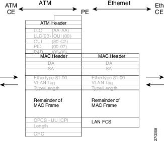
Figure 21-1 Protocol Stack for ATM AAL5 to Ethernet Local Switching Bridged Interworking—With VLAN Header
In Cisco IOS Release 12.2(33)SB, the Ethernet/VLAN to ATM AAL5 AToM has the following restrictions:
•
–
–
•
•
•
•
•
•
•
•
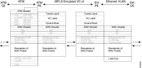
Figure 21-2 Protocol Stack for ATM to Ethernet AToM Bridged Interworking—With VLAN Header
ATM AAL5 to Ethernet Local Switching—Bridged Interworking
This interworking type provides interoperability between Ethernet attachment VC and ATM attachment VC connected to the same PE router. For this interworking type, Bridged encapsulation is used, corresponding to the Bridged Interworking mechanism.
•
•
Figure 21-3 shows the protocol stack for ATM to Ethernet local switching -bridged interworking. The ATM side has an encapsulation type as aal5snap.
Figure 21-3 Protocol Stack for ATM AAL5 to Ethernet Local Switching Bridged Interworking
ATM AAL5 to VLAN 802.1Q Local Switching—Bridged Interworking
This interworking type provides interoperability between ATM attachment VC and Ethernet VLAN attachment VC connected to the same PE router. As in the ATM to Ethernet case, Bridged encapsulation is used, corresponding to Bridged (Ethernet) Interworking mechanism.
In case of Ethernet VLAN attachment, the VLAN ID is a service delimiter, so the VLAN header is not included in the frame to and from the ATM CE.
•
•
The protocol stack for ATM to VLAN local switching is shown in Figure 21-3. The ATM side has an encapsulation type of aal5snap.
ATM AAL5 to Ethernet Port AToM—Bridged Interworking
This interworking type provides interoperability between ATM attachment VC and Ethernet attachment VC connected to different PE routers. Bridged encapsulation is used, corresponding to the Bridged (Ethernet) Interworking mechanism.
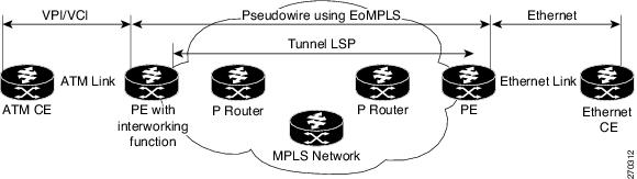
The interworking function is performed at the PE connected to the ATM attachment VC based on Multiprotocol Encapsulation over ATM Adaptation Layer 5 (Figure 21-4).
Figure 21-4 Network Topology for ATM to Ethernet AToM Bridged Interworking
The advantage of this architecture is that the Ethernet PE (connected to the Ethernet segment) operates similarly to Ethernet like-to-like services.
On the PE with Interworking function, in the direction from the ATM segment to MPLS cloud, the bridged encapsulation (ATM/SNAP header) is discarded and the Ethernet frame is encapsulated with the labels required to go through the pseudowire using the VC type 5 (Ethernet) (Figure 21-5).
In the opposite direction, after the label disposition from the MPLS cloud, Ethernet frames are encapsulated over AAL5 using bridged encapsulation.
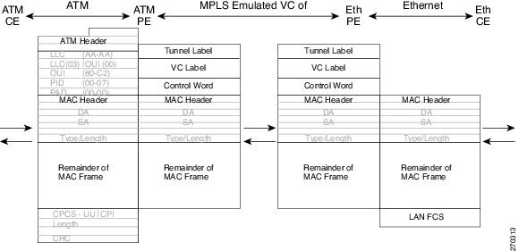
Figure 21-5 shows the protocol stack for ATM to Ethernet AToM Bridged Interworking. The ATM side has an encapsulation type of aal5snap.
Figure 21-5 Protocol Stack for ATM to Ethernet AToM Bridged Interworking—Without VLAN Header
ATM AAL5 to Ethernet VLAN 802.1Q AToM—Bridged Interworking
This interworking type provides interoperability between ATM attachment VC and Ethernet VLAN attachment VC connected to different PE routers. Bridged encapsulation is used, corresponding to the Bridged (Ethernet) Interworking mechanism.
The interworking function is performed in the same way as for the ATM to Ethernet Port case, implemented on the PE connected to the ATM attachment VC. The implementation is based on Multiprotocol Encapsulation over ATM Adaptation Layer 5 (see Figure 21-4).
For the PE connected to the Ethernet side, one major difference exists due the existence of the VLAN header in the incoming packet. The PE discards the VLAN header of the incoming frames from the VLAN CE, and the PE inserts a VLAN header into the Ethernet frames traveling from the MPLS cloud. The frames sent on the pseudowire (with VC type 5) are Ethernet frames without the VLAN header.
Encapsulation over ATM Adaptation Layer 5, as shown in Figure 21-6.
Figure 21-6 Protocol Stack for ATM to VLAN AToM Bridged Interworking
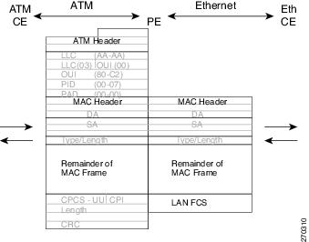
ATM to Ethernet—Routed Interworking
To perform routed interworking, both the ATM PE and Ethernet PE routers must be configured. Figure 21-7 shows the routed interworking between ATM to Ethernet. The IP encapsulation over the pseudowire is performed on the ATM packets arriving from the ATM CE router.
The address resolution is done at the ATM PE router; it is required when the ATM CE router does an inverse ARP. It is not required when the ATM CE router is configured using P2P subinterfaces or static maps.
When packets arrive from the Ethernet CE router, the Ethernet PE router removes the L2 frame tag, and then forwards the IP packet to the egress PE router, using IPoMPLS encapsulation over the pseudowire. The Ethernet PE router makes the forwarding decision based on the L2 circuit ID, the VLAN ID, or port ID, of the incoming L2 frame. At the ATM PE router, after label disposition, the IP packets are encapsulated over the AAL5 using routed encapsulation based on RFC 2684.
The address resolution at the Ethernet PE router can be done when the Ethernet CE router configures the static ARP, or by the proxy ARP on the Ethernet PE. If the proxy ARP is used, the IP address of the remote CE can be learned dynamically. Routing protocols need to be configured to operate in the P2P mode on the Ethernet CE.
Figure 21-7 Protocol Stack for ATM to Ethernet—Routed Interworking
Configuration Tasks and Examples
This section describes configuration tasks for and provides examples of two L2VPN technology solutions:
•
Local Switching
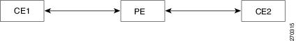
Figure 21-8 shows different LS configurations.
Figure 21-8 Local Switching Model for CLI Commands
This section explains the following LS configurations and their examples:
•
ATM AAL5 to Ethernet Port
You can configure the ATM AAL5 to Ethernet Port feature on a PE router using the following steps:
1.
2.
3.
4.
5.
6.
7.
Note
Note
The following example shows how you can configure the ATM AAL5 to Ethernet Port feature on a PE router using routed interworking:
config tinterface atm 2/0/0pvc 0/200 l2transportencapsulation aal5snapinterface gigabitethernet 5/1/0connect atm-enet gigabitethernet 5/1/0 atm 2/0/0 0/200 interworking ipATM AAL5 to Ethernet VLAN 802.1Q
You can configure the ATM AAL5 to Ethernet VLAN 802.1Q feature on a PE router using the following steps:
1.
2.
3.
4.
5.
6.
7.
Note
The following example shows how to configure the ATM AAL5 to Ethernet VLAN 802.1Q feature on a PE router using bridged interworking:
config tinterface atm 2/0/0pvc 0/200 l2transportencapsulation aal5snapinterface gigabitethernet 5/1/0.3encapsulation dot1q 2connect atm-vlan gigabitethernet 5/1/0.3 atm 2/0/0 0/200 interworking ethernetAToM
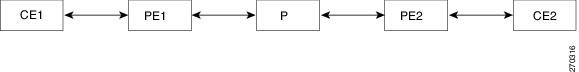
Figure 21-9 illustrates different AToM configurations.
Figure 21-9 AToM Model for CLI Commands
This section explains the following AToM configurations and their examples:
•
ATM AAL5 to Ethernet Port
You can configure the ATM AAL5 to Ethernet Port feature on a PE1 router using the following steps:
1.
2.
3.
4.
5.
6.
7.
8.
9.
10.
11.
You can configure the ATM AAL5 to Ethernet Port feature on a PE2 router using the following steps:
1.
2.
3.
4.
5.
6.
7.
8.
9.
Note
The following example shows how to configure the ATM AAL5 to Ethernet Port feature on a PE1 router, using routed interworking:
config tmpls label protocol ldpinterface Loopback100ip address 10.0.0.100 255.255.255.255pseudowire-class atm-ethencapsulation mplsinterworking ipinterface atm 2/0/0pvc 0/200 l2transportencapsulation aal5xconnect 10.0.0.200 140 pw-class atm-ethThe following example shows how to configure the ATM AAL5 to Ethernet Port feature on a PE2 router, using routed interworking:
config tmpls label protocol ldpinterface Loopback200ip address 10.0.0.200 255.255.255.255pseudowire-class atm-ethencapsulation mplsinterworking ipinterface gigabitethernet 5/1/0xconnect 10.0.0.100 140 pw-class atm-ethConfiguring ATM AAL5 to Ethernet VLAN 802.1Q
You can configure the ATM AAL5 to Ethernet VLAN 802.1Q feature on a PE1 router using the following steps:
1.
2.
3.
4.
5.
6.
7.
8.
9.
10.
11.
You can configure the ATM AAL5 to Ethernet VLAN 802.1Q feature on a PE2 router using the following steps:
1.
2.
3.
4.
5.
6.
7.
8.
9.
10.
Note
The following example shows how to configure the ATM AAL5 to Ethernet VLAN 802.1Q feature on a PE1 router using bridged interworking:
config tmpls label protocol ldpinterface Loopback100ip address 10.0.0.100 255.255.255.255pseudowire-class atm-vlanencapsulation mplsinterworking ethernetinterface atm 2/0/0pvc 0/200 l2transportencapsulation aal5snapxconnect 10.0.0.200 140 pw-class atm-vlanThe following example shows how to configure the ATM AAL5 to Ethernet VLAN 802.1Q feature on a PE2 router using bridged interworking:
config tmpls label protocol ldpinterface Loopback200ip address 10.0.0.200 255.255.255.255pseudowire-class atm-vlanencapsulation mplsinterworking ethernetinterface gigabitethernet 5/1/0.3encapsulation dot1q 1525xconnect 10.0.0.100 140 pw-class atm-vlan
Note
Ethernet/VLAN to Frame Relay Interworking
The Ethernet VLAN to Frame Relay (FR) Interworking feature is described in the following topics:
•
•
•
•
•
•
•
•
Prerequisites of Ethernet/VLAN to Frame Relay Interworking
Before you configure Ethernet/VLAN to Frame Relay Interworking on a network, you must enable Cisco Express Forwarding.
Restrictions for Ethernet/VLAN to Frame Relay Interworking
In Cisco IOS Release 12.2(33)SB, the Ethernet/VLAN to Frame Relay LS has the following restrictions:
•
–
–
•
•
•
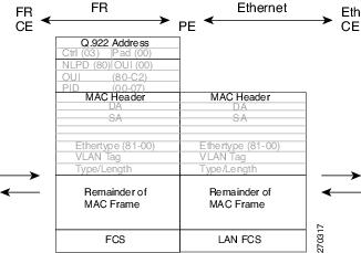
Figure 21-10 Protocol Stack for FR to Ethernet Local Switching Bridged Interworking—With VLAN Header
In Cisco IOS Release 12.2(33)SB, the Ethernet/VLAN to Frame Relay AToM has the following restrictions:
•
–
–
•
•
•
•
•
•
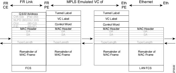
Figure 21-11 Protocol Stack for FR to Ethernet AToM Bridged Interworking—With VLAN Header
FR DLCI to Ethernet Local Switching—Bridged Interworking
This interworking type provides interoperability between Frame Relay attachment VC and Ethernet attachment VC connected to the same PE router. For this interworking type, Bridged encapsulation is used, corresponding to Bridged (Ethernet) Interworking mechanism.
•
•
Figure 21-12 shows the protocol stack for FR to Ethernet local switching (bridged interworking).
Figure 21-12 Protocol Stack for FR to Ethernet Local Switching Bridged Interworking
The PE router automatically supports translation of both Cisco and IETF FR encapsulation types traveling from the CE, but translates only to IETF when sending to the CE router. This is not a problem for the Cisco CE router, because it can manage IETF encapsulation on receipt even if it is configured to send a Cisco encapsulation.
FR DLCI to VLAN 802.1Q Local Switching—Bridged Interworking
This interworking type provides interoperability between Frame Relay Attachment VC and Ethernet VLAN Attachment VC connected to the same PE router. For this interworking type the Bridged Encapsulation is used, corresponding to Bridged (Ethernet) Interworking mechanism.
In the case of an Ethernet VLAN attachment, the VLAN ID is a service delimiter, so the VLAN header is not included in the frame to or from the FR CE.
•
•
The protocol stack for FR to Ethernet local switching (bridged interworking) is shown in Figure 21-12.
FR DLCI to Ethernet Port AToM—Bridged Interworking
This interworking type provides interoperability between FR attachment VC and Ethernet attachment VC connected to different PE routers. Bridged encapsulation is used, corresponding to the Bridged (Ethernet) Interworking mechanism.
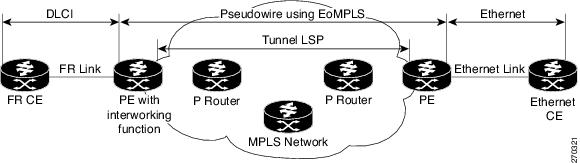
For an FR to Ethernet Port case, the interworking function is performed at the PE connected to the FR attachment VC based on multiprotocol interconnect over Frame Relay (Figure 21-13). The Interworking is implemented similar to an ATM-to-Ethernet case.
Figure 21-13 Network Topology for FR to Ethernet AToM Bridged Interworking
The advantage of this architecture is that the Ethernet PE (connected to the Ethernet segment) operates similarly to Ethernet like-to-like services: a pseudowire label is assigned to the Ethernet port and then the remote Label Distribution Protocol (LDP) session distributes the labels to its peer PE. Ethernet frames are carried through the MPLS network using Ethernet over MPLS (EoMPLS).
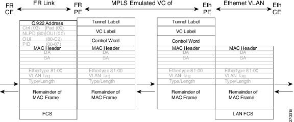
On the PE with Interworking function, in the direction from the FR segment to MPLS cloud, the bridged encapsulation (FR/SNAP header) is discarded and the Ethernet frame is encapsulated with the labels required to go through the pseudowire using the VC type 5 (Ethernet) (Figure 21-14).
In the opposite direction, after the label disposition from the MPLS cloud, Ethernet frames are encapsulated over FR using bridged encapsulation.
The Figure 21-14 shows the protocol stack for FR to Ethernet Bridged Interworking.
Figure 21-14 Protocol Stack for FR to Ethernet AToM Bridged Interworking—Without VLAN Header
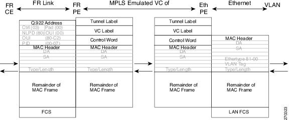
FR DLCI to Ethernet VLAN 802.1Q AToM—Bridged Interworking
This interworking type provides interoperability between FR attachment VC and Ethernet VLAN Attachment VC connected to different PE routers. The bridged encapsulation is used, corresponding to the Bridged (Ethernet) Interworking mechanism.
The interworking function is performed in the same way as for FR to Ethernet port case, implemented on the PE connected to the FR attachment VC, based upon a multiprotocol interconnect over Frame Relay (see Figure 21-14).
As in the ATM to VLAN case, one difference exists on Ethernet side due the existence of the VLAN header in the incoming packet. The PE on the VLAN side discards the VLAN header of the incoming frames from the VLAN CE, and the PE inserts a VLAN header into the Ethernet frames traveling from the MPLS cloud. The frames sent on the pseudowire (with VC type 5) are Ethernet frames without the VLAN header.
The Figure 21-15 shows the protocol stack for FR to VLAN AToM Bridged Interworking.
Figure 21-15 Protocol Stack for FR to VLAN AToM Bridged Interworking
Frame Relay to Ethernet—Routed Interworking
To perform routed interworking, both the FR PE and Ethernet PE routers must be configured. When FR packets arrive from the FR CE router, the FR PE router removes the frame relay header. The FR PE router forwards the IP packet to the egress PE router using IPoMPLS encapsulation over the pseudowire. At the Ethernet PE router, after label disposition, the IP packets are encapsulated with an MAC rewrite.
The address resolution is done at the FR PE router and is required when the FR CE router does an inverse ARP. It is not required when the the FR CE router is configured using P2P subinterfaces or static maps.
For packets arriving from the Ethernet CE router, the Ethernet PE router removes the L2 framing. The Ethernet PE router forwards the IP packet to the egress PE router, using IPoMPLS encapsulation over the pseudowire. The Ethernet PE router makes the forwarding decision based on the L2 circuit ID (VLAN ID or port ID) of the incoming L2 frame. At the FR PE router, after label disposition, the IP packets are encapsulated over FR, using routed encapsulation based on RFC 2427.
The address resolution is also done at the Ethernet PE router by configuring static ARP on the Ethernet CE router, or by implementing proxy ARP on the Ethernet PE router. If a proxy ARP is used, the IP address of the remote CE router can be learned dynamically, or can be statically configured in the PE router. Routing protocols need to be configured to operate in a point-to-point mode on the Ethernet CE router.
Packets that arrive either from the FR CE or the Ethernet CE router with unsupported translations are dropped.
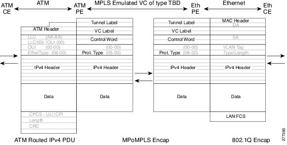
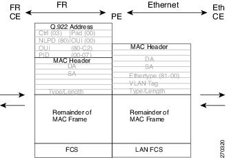
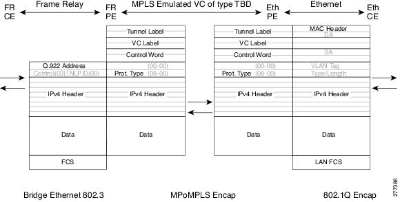
Figure 21-16 shows an example of the protocol stacks at the PEs when IPv4 PDUs are exchanged using routed interworking. Other than IPv4, the Prot_Type field is used while carrying L3 packets.
Figure 21-16 Protocol Stacks for FR to Ethernet Routed Interworking
Configuration Tasks and Examples
This section describes configuration tasks for and examples of two L2VPN technology solutions
•
Local Switching
Figure 21-8 shows LS configurations. The following LS configurations and examples are described:
•
FR DLCI to Ethernet Port
You can configure the FR DLCI to Ethernet port feature on a router using the following steps:
1.
2.
3.
4.
5.
6.
7.
8.
9.
Note
Note
The following example shows how you can configure the FR DLCI to Ethernet Port feature on a router, using routed interworking:
config tframe-relay switchinginterface serial 2/0/0:1encapsulation frame-relayframe-relay intf-type dceframe-relay interface-dlci 100 switchedinterface gigabitethernet 5/1/0connect fr-enet gigabitethernet 5/1/0 serial 2/0/0:1 100 interworking ipFR DLCI to Ethernet VLAN 802.1Q
You can configure the FR DLCI to Ethernet VLAN 802.1Q feature on a router using the following steps:
1.
2.
3.
4.
5.
6.
7.
8.
9.
Note
The following example shows how you can configure the FR DLCI to Ethernet VLAN 802.1Q feature on a router using bridged interworking:
config tframe-relay switchinginterface serial 2/0/0:1encapsulation frame-relayframe-relay intf-type dceframe-relay interface-dlci 100 switchedinterface gigabitethernet 5/1/0.3encapsulation dot1q 2connect fr-vlan gigabitethernet 5/1/0.3 serial 2/0/0:1 100 interworking ethernetAToM
Figure 21-9 illustrates different AToM configurations. This section explains the following AToM configurations and provides examples:
•
FR DLCI to Ethernet Port
You can configure the FR DLCI to Ethernet port feature on a PE1 router using the following steps:
1.
2.
3.
4.
5.
6.
7.
8.
9.
10.
11.
12.
13.
You can configure the FR DLCI to Ethernet port feature on a PE2 router using the following steps:
1.
2.
3.
4.
5.
6.
7.
8.
9.
Note
The following example shows how to configure the FR DLCI to Ethernet port feature on a PE1 router, using routed interworking:
config tmpls label protocol ldpinterface Loopback100ip address 10.0.0.100 255.255.255.255pseudowire-class fr-ethencapsulation mplsinterworking ipframe-relay switchinginterface serial 2/0/0:1encapsulation frame-relayframe-relay intf-type dceframe-relay interface-dlci 567 switchedconnect mpls serial 2/0/0:1 567 l2transportxconnect 10.0.0.200 150 pw-class fr-ethThe following example shows how to configure the FR DLCI to an Ethernet port feature on a PE2 router, using routed interworking:
config tmpls label protocol ldpinterface Loopback200ip address 10.0.0.200 255.255.255.255pseudowire-class fr-ethencapsulation mplsinterworking ipinterface gigabitethernet 5/1/0xconnect 10.0.0.100 150 pw-class fr-ethFR DLCI to Ethernet VLAN 802.1Q
To configure the FR DLCI to Ethernet VLAN 802.1Q feature on a PE1 router, use the following steps:
1.
2.
3.
4.
5.
6.
7.
8.
9.
10.
11.
12.
13.
14.
To configure the FR DLCI to Ethernet VLAN 802.1Q feature on a PE2 router, use the following steps:
1.
2.
3.
4.
5.
6.
7.
8.
9.
10.
Note
The following example shows how to configure the FR DLCI to Ethernet VLAN 802.1Q feature on a PE1 router using bridged interworking:
config tmpls label protocol ldpinterface Loopback100ip address 10.0.0.100 255.255.255.255pseudowire-class fr-vlanencapsulation mplsinterworking ethernetframe-relay switchinginterface serial 2/0/0:1encapsulation frame-relayframe-relay intf-type dceconnect mpls serial 2/0/0:1 567 l2transportxconnect 10.0.0.200 150 pw-class fr-vlanThe following example shows how to configure the FR DLCI to Ethernet VLAN 802.1Q feature on a PE2 router using bridged interworking:
config tmpls label protocol ldpinterface Loopback200ip address 10.0.0.200 255.255.255.255pseudowire-class fr-vlanencapsulation mplsinterworking ethernetinterface gigabitethernet 5/1/0.3encapsulation dot1q 1525xconnect 10.0.0.100 150 pw-class fr-vlan
Note
ATM to Frame Relay—Routed Interworking
To perform routed interworking, the ATM and FR PE router must be configured. Routing protocols must also be configured to operate in the P2P mode. ATM packets arriving from the ATM CE router are translated into IP encapsulation over the pseudowire.
When packets arrive from the FR CE router, the FR PE router removes the L2 framing, and forwards the IP packet to the egress PE router, using IPoMPLS encapsulation over the pseudowire. The FR PE router makes the forwarding decision based on the L2 circuit ID (DLCI number) of the incoming L2 frame. The FR CE router can use static map of IP address to DLCI number.
At the ATM PE router, after label disposition, the IP packets are encapsulated over the AAL5, using routed encapsulation.
Address resolution is done at the ATM PE router, if the ATM CE router is doing inverse ARP. It is not required if the ATM CE router is configured using P2P subinterfaces or static maps.
Packets arriving from either ATM CE or FR CE routers with unsupported translations are dropped.
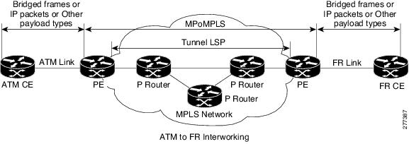
Figure 21-17 demonstrates ATM to FR routed interworking.
Figure 21-17 ATM to Frame Relay Routed Interworking
Configuration Tasks and Examples
This section describes configuration tasks for and examples of two L2VPN technology solutions
•
Local Switching
Figure 21-8 shows LS configurations. This section explains LS configuration of the ATM AAL5 to FR DLCI feature and provides examples.
ATM AAL5 to FR DLCI
To configure the ATM AAL5 to FR DLCI feature on a router, use the following steps:
1.
2.
3.
4.
5.
6.
7.
8.
The following example shows how to configure the ATM AAL5 to FR DLCI feature on a router:
config tinterface atm 2/0/0pvc 0/200 l2transportencapsulation aal5snapframe-relay switchinginterface serial 2/0/0:1encapsulation frame-relayframe-relay intf-type dceframe-relay interface-dlci 100 switchedconnect atm-dlci atm 2/0/0 0/200 serial 2/0/0:1 100 interworking ipAToM
Figure 21-9 illustrates different AToM configurations. This section explains the FR DLCI to ATM AAL5 configurations and provides examples:
FR DLCI to ATM AAL5
To configure the FR DLCI to ATM AAL5 feature on a PE1 router, use the following steps:
1.
2.
3.
4.
5.
6.
7.
8.
9.
10.
11.
To configure the FR DLCI to ATM AAL5 feature on a PE2 router, use the following steps:
1.
2.
3.
4.
5.
6.
7.
8.
9.
10.
11.
12.
13.
14.
The following example shows how to configure the FR DLCI to ATM AAL5 feature on a PE1 router:
config tmpls label protocol ldpinterface Loopback100ip address 10.0.0.100 255.255.255.255pseudowire-class atm-frencapsulation mplsinterworking ipinterface atm 2/0/0pvc 0/200 l2transportencapsulation aal5xconnect 10.0.0.200 140 pw-class atm-frThe following example shows how to configure the FR DLCI to ATM AAL5 feature on a PE2 router:
config tmpls label protocol ldpinterface Loopback100ip address 10.0.0.200 255.255.255.255pseudowire-class atm-frencapsulation mplsinterworking ipframe-relay switchinginterface serial 2/0/0:1encapsulation frame-relayframe-relay intf-type dceframe-relay interface-dlci 567 switchedconnect mpls serial 2/0/0:1 567 l2transportxconnect 10.0.0.100 150 pw-class atm-frVerifying L2VPN Interworking
To verify the L2VPN status - local switching, use the following commands:
•
•
To view the L2VPN statistics - local switching, use the following command:
•
To verify the L2VPN status - AToM, use the following commands:
•
•
•
•
•
To verify the L2VPN statistics - AToM, use the following commands:
•
•