Table Of Contents
Configuring Automatic Protection Switching
Multirouter Automatic Protection Switching
Feature History for MR-APS
Restrictions for MR-APS
Configuration Tasks for MR-APS
Configuring MR-APS on Unchannelized Line Cards
Configuring MR-APS on Channelized Line Cards
Configuring MR-APS with Static Routes
Configuring MR-APS with Static Routes on Unchannelized Line Cards
Configuring MR-APS with Static Routes on Channelized Line Cards
Monitoring and Maintaining the MR-APS Configuration
Single-router Automatic Protection Switching
Feature History for SR-APS
Configuring SR-APS
Disabling SR-APS
Monitoring and Maintaining the SR-APS Configuration
Threshold Commands
Specifying SR-APS Signal Degrade BER Threshold
Specifying SR-APS Signal Fail BER Threshold
Configuring Automatic Protection Switching
Automatic protection switching (APS) is a protection mechanism for SONET networks that enables SONET connections to switch to another SONET circuit when a circuit failure occurs. A protect interface serves as the backup interface for the working interface. When the working interface fails, the protect interface quickly assumes its traffic load. This chapter describes the following APS features:
•
Multirouter Automatic Protection Switching
•
Single-router Automatic Protection Switching
Multirouter Automatic Protection Switching
The Multirouter Automatic Protection Switching (MR-APS) feature enables interface connections to switch from one circuit to another circuit if a circuit failure occurs. Interfaces can be switched in response to a router failure, degradation or loss of channel signal, or manual intervention. In a multirouter environment, the Multirouter APS (MR-APS) feature allows the protect SONET interface to reside in a different router from the working SONET interface.
The protection mechanism used for this feature has a linear 1+1 architecture as described in the Bellcore publication TR-TSY-000253, SONET Transport Systems; Common Generic Criteria, Section 5.3. The connection may be bidirectional, and revertive or nonrevertive. Unidirectional MR-APS is not supported. The default is bidirectional. The switching mode must be the same on the far end of the connection.
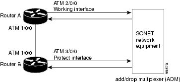
In the 1+1 architecture, a protect interface (circuit) is paired with each working interface. Normally, the protect and working interfaces are connected to an ADM (add/drop multiplexer), which sends the same signal payload to the working and protect interfaces.
Figure 1 shows a multirouter APS configuration. In the figure, the working and protect circuits terminate on different line cards that are installed in two different routers. Interfaces in a multirouter APS configuration can be configured with either SONET or SDH framing.
Figure 14-1 Multirouter APS Configuration
On the protect circuit, the K1 and K2 bytes from the line overhead (LOH) of the SONET frame indicate the current status of the APS connection and convey any requests for action. This signalling channel is used by the two ends of the connection to maintain synchronization.
The working and protect circuits themselves, within the router or routers in which they terminate, are synchronized over an independent communication channel, not involving the working and protect circuits. In Figure 14-1, this independent channel may be a different ATM connection or a lower-bandwidth connection. In a router configured for multirouter APS, the configuration for the protect interface includes the IP address of the router (normally its loopback address) that has the working interface.
This chapter describes the MR-APS feature in the following topics:
•
Feature History for MR-APS
•
Restrictions for MR-APS
•
Configuration Tasks for MR-APS
•
Monitoring and Maintaining the MR-APS Configuration
Feature History for MR-APS
Cisco IOS Release
|
Description
|
Required PRE
|
12.0(23)SX
|
This feature was introduced on the Cisco 10000 series router.
|
PRE1
|
12.0(26)S
|
This feature was integrated into Cisco IOS Release 12.0(26)S.
|
PRE1
|
12.3(7)XI2
|
This feature was integrated into Cisco IOS Release 12.3(7)XI2.
|
PRE2
|
12.2(28)SB
|
This feature was integrated into Cisco IOS Release 12.2(28)SB.
|
PRE2
|
Restrictions for MR-APS
In Cisco IOS Releases 12.3(7)XI2 and 12.2(28)SB, MR-APS is supported for the following line cards:
•
4-Port OC3/STM-1 ATM line card
•
1-Port OC-12 ATM line card
•
1-Port Channelized OC-12/STM-4 line card
•
4-Port Channelized OC-3/STM-1 line card
In Cisco IOS Release 12.0(26)S, MR-APS is also supported for the following line cards:
•
6-Port OC-3/STM-1 Packet over SONET line card
•
1-Port OC-12 Packet over SONET line card
Configuration Tasks for MR-APS
To configure the MR-APS feature, perform the following tasks:
•
Configuring MR-APS on Unchannelized Line Cards
•
Configuring MR-APS on Channelized Line Cards
•
Configuring MR-APS with Static Routes
Configuring MR-APS on Unchannelized Line Cards
To configure MR-APS on unchannelized line cards, enter the following commands beginning in global configuration mode.
|
Command
|
Purpose
|
Step 1
|
Router(config)# redundancy
|
Enters redundancy configuration mode, which allows you to associate two line cards as a redundant pair.
|
Step 2
|
Router(config-r)# associate slot slot-one
mr-aps
|
Logically associates slots for APS processor redundancy.
To allow MR-APS to operate, you must associate a slot on the working interface of one router and with a corresponding protect interface on a second router.
|
Step 3
|
Router(config-r)# exit
|
Exits redundancy configuration mode and returns to global configuration mode.
|
Step 4
|
Router(config)# interface type number
|
Specifies the interface type and number. Enters interface configuration mode.
|
Step 5
|
Router(config-if)# aps group group-number
|
Permits more than one APS protect and working interface to be supported on a router.
|
Step 6
|
Router(config-if)# aps working circuit-number
|
Configures an interface as a working interface.
|
Step 7
|
Router(config-if)# exit
|
Exits interface configuration mode and returns to global configuration mode.
|
Step 8
|
Repeat steps 1 through 5 on the second router to configure the protect interface. Substitute the appropriate slot numbers, interface types, and interface numbers. After you complete step 5, go to step 9.
|
Step 9
|
Router(config-if)# aps protect circuit-number
ip-address
|
Configures an interface as a protect interface.
The ip-address argument specifies the IP address of the router that has the working interface.
|
Step 10
|
Router(config-if)# exit
|
Exits interface configuration mode and returns to global configuration mode.
|
Configuring MR-APS on Channelized Line Cards
To configure MR-APS on channelized line cards, enter the following commands beginning in global configuration mode.
|
Command
|
Purpose
|
Step 1
|
Router(config)# redundancy
|
Enters redundancy configuration mode, which allows you to associate two line cards as a redundant pair.
|
Step 2
|
Router(config-r)# associate slot slot-one
mr-aps
|
Logically associates slots for APS processor redundancy.
To allow MR-APS to operate, you must associate a slot on the working interface of one router and with a corresponding protect interface on a second router.
|
Step 3
|
Router(config-r)# exit
|
Exits redundancy configuration mode and returns to global configuration mode.
|
Step 4
|
Router(config)# controller SONET
slot#/subslot#/port#
|
Specifies the interface type and number. Enters controller configuration mode.
|
Step 5
|
Router(config-controller)# aps group
group-number
|
Permits more than one APS protect and working interface to be supported on a router.
|
Step 6
|
Router(config-controller)# aps working
circuit-number
|
Configures an interface as a working interface.
|
Step 7
|
Router(config-controller)# exit
|
Exits controller configuration mode and returns to global configuration mode.
|
Step 8
|
Repeat steps 1 through 5 on the second router to configure the protect interface. Substitute the appropriate slot numbers, interface types, and interface numbers. After you complete step 5, go to step 9.
|
Step 9
|
Router(config-controller)# aps protect
circuit-number ip-address
|
Configures an interface as a protect interface.
The ip-address argument specifies the IP address of the router that has the working interface.
|
Step 10
|
Router(config-controller)# exit
|
Exits controller configuration mode and returns to global configuration mode.
|
Example 14-1 shows the configuration of MR-APS on ATM interfaces. In the example, Router A is configured with the working interface, and Router B is configured with the protect interface. If the working interface on Router A becomes unavailable, the connection automatically switches over to the protect interface on Router B.
Example 14-1 Configuring MR-APS
Router A (working interface)
ip address 10.7.7.7 255.255.255.0
Router B (protect interface)
ip address 10.7.7.6 255.255.255.0
Configuring MR-APS with Static Routes
To configure MR-APS with static routes, perform the following procedures:
•
Configuring MR-APS with Static Routes on Unchannelized Line Cards
•
Configuring MR-APS with Static Routes on Channelized Line Cards
Configuring MR-APS with Static Routes on Unchannelized Line Cards
To optionally configure MR-APS with static routes on unchannelized line cards, enter the following commands beginning in global configuration mode:
|
Command
|
Purpose
|
Step 1
|
Router(config)# redundancy
|
Enters redundancy configuration mode, which allows you to associate two line cards as a redundant pair.
|
Step 2
|
Router(config-r)# associate slot slot-one
mr-aps
|
Logically associates slots for APS processor redundancy.
To allow MR-APS to operate, you must associate a slot on the working interface of one router and with a corresponding protect interface on a second router.
|
Step 3
|
Router(config-r)# exit
|
Exits redundancy configuration mode and returns to global configuration mode.
|
Step 4
|
Router(config)# ip route prefix mask
{ip-address | interface-type interface-number
[ip-address]} [distance] [name] [permanent]
[tag tag]
|
Configures a static IP address.
When configuring APS, we recommend that you specify the optional IP address of the interface to improve routing performance.
|
Step 5
|
Router(config)# interface type number
|
Specifies the interface type and number. Enters interface configuration mode or controller configuration mode.
|
Step 6
|
Router(config-if)# ip route static update
immediate
|
(Optional) Specifies that static routes will be added to the routing table immediately after the interface becomes active.
|
Step 7
|
Router(config-if)# carrier-delay [seconds |
msec seconds]
|
Sets the carrier delay timer value in seconds or milliseconds.
This command allows you to filter link outages and to not report them as a link down event if they occur before the carrier delay timer expires. In MR-APS, system performance can be enhanced if link-down event messages are kept to a minimum.
|
Step 8
|
Router(config-if)# aps group group-number
|
Permits more than one APS protect and working interface to be supported on a router.
|
Step 9
|
Router(config-if)# aps working circuit-number
|
Configures an interface as a working interface.
|
Step 10
|
Router(config-if)# exit
|
Exits interface configuration mode and returns to global configuration mode.
|
Step 11
|
Repeat steps 1 through 8 on the second router to configure the protect interface. Substitute the appropriate slot numbers, IP addresses, interface types, and interface numbers. After you complete step 8, go to step 12.
|
Step 12
|
Router(config-if)# aps protect circuit-number
ip-address
|
Configures an interface as a protect interface.
The ip-address argument specifies the IP address of the router that has the working interface.
|
Step 13
|
Router(config-if)# exit
|
Exits interface configuration mode and returns to global configuration mode.
|
Configuring MR-APS with Static Routes on Channelized Line Cards
To optionally configure MR-APS with static routes on channelized line cards, enter the following commands beginning in global configuration mode:
|
Command
|
Purpose
|
Step 1
|
Router(config)# redundancy
|
Enters redundancy configuration mode, which allows you to associate two line cards as a redundant pair.
|
Step 2
|
Router(config-r)# associate slot slot-one
mr-aps
|
Logically associates slots for APS processor redundancy.
To allow MR-APS to operate, you must associate a slot on the working interface of one router and with a corresponding protect interface on a second router.
|
Step 3
|
Router(config-r)# exit
|
Exits redundancy configuration mode and returns to global configuration mode.
|
Step 4
|
Router(config)# ip route prefix mask
{ip-address | interface-type interface-number
[ip-address]} [distance] [name] [permanent]
[tag tag]
|
Configures a static IP address.
When configuring APS, we recommend that you specify the optional IP address of the interface to improve routing performance.
|
Step 5
|
Router(config)# controller SONET
slot#/subslot#/port#
|
Specifies the interface type and number. Enters controller configuration mode.
|
Step 6
|
Router(config-controller)# ip route static
update immediate
|
(Optional) Specifies that static routes will be added to the routing table immediately after the interface becomes active.
|
Step 7
|
Router(config-controller)# carrier-delay
[seconds | msec seconds]
|
Sets the carrier delay timer value in seconds or milliseconds.
This command allows you to filter link outages and to not report them as a link down event if they occur before the carrier delay timer expires. In MR-APS, system performance can be enhanced if link-down event messages are kept to a minimum.
|
Step 8
|
Router(config-controller)# aps group
group-number
|
Permits more than one APS protect and working interface to be supported on a router.
|
Step 9
|
Router(config-controller)# aps working
circuit-number
|
Configures an interface as a working interface.
|
Step 10
|
Router(config-controller)# exit
|
Exits controller configuration mode and returns to global configuration mode.
|
Step 11
|
Repeat steps 1 through 8 on the second router to configure the protect interface. Substitute the appropriate slot numbers, IP addresses, interface types, and interface numbers. After you complete step 8, go to step 12.
|
Step 12
|
Router(config-controller)# aps protect
circuit-number ip-address
|
Configures an interface as a protect interface.
The ip-address argument specifies the IP address of the router that has the working interface.
|
Step 13
|
Router(config-controller)# exit
|
Exits controller configuration mode and returns to global configuration mode.
|
Example 14-2 shows the configuration of multirouter APS with static routes on ATM interfaces. Router A is configured with the working interface, and Router B is configured with the protect interface. If the working interface on Router A becomes unavailable, the connection automatically switches over to the protect interface on Router B. Note that 172.16.1.0 is the address of the traffic destination network and that the route over the Peer Group Protocol (PGP) link has a higher distance metric number than the multirouter APS working interface.
Example 14-2 Configuring MR-APS with Static Routes
Router A (working interface)
ip address 10.7.7.7 255.255.255.0
ip route static update immediate
ip route 172.16.1.0 255.255.255.0 atm 2/0/0 10
ip route 172.16.1.0 255.255.255.0 atm 1/0/0 10.7.7.6 20
Router B (protect interface)
ip address 10.7.7.6 255.255.255.0
ip route static update immediate
ip route 172.16.1.0 255.255.255.0 atm 3/0/0 10
ip route 172.16.1.0 255.255.255.0 atm 1/0/0 10.7.7.7 20
Monitoring and Maintaining the MR-APS Configuration
To monitor and maintain the configuration of MR-APS, enter any of the following commands in privileged EXEC mode:
Command
|
Purpose
|
Router# show aps
|
Displays about APS-configured interfaces.
|
Router# debug aps
|
Displays debugging information related automatic protection switching.
|
Router(config-if)# aps force circuit-number
(unchannelized line cards)
or
Router(config-controller)# aps force
circuit-number (channelized line cards)
|
Manually switches the specified circuit to a protect interface, unless a request of equal or higher priority is in effect.
circuit-number is the number of the circuit to switch to the protect interface.
Note This command has no effect if the protection channel is already the active channel.
|
Router(config-if)# aps manual circuit-number
(unchannelized line cards)
or
Router(config-controller)# aps manual
circuit-number (channelized line cards)
|
Manually switches a circuit to a protect interface.
|
Router# aps lockout [POS | SONET]
slot#/subslot#/port#
|
Prevents a channel from automatically switching to the active, working, or protection state.
|

Caution 
Because debugging output is assigned high priority in the CPU process, it can render the system unusable. For this reason, use debug commands only to troubleshoot specific problems or during troubleshooting sessions with Cisco Systems technical support personnel. Moreover, it is best to use debug commands during periods of lower network traffic and fewer users. Debugging during these periods decreases the likelihood that increased debug command processing overhead will affect system use.
Single-router Automatic Protection Switching
The Cisco 10000 series router supports SONET Single-router Automatic Protection Switching (SR-APS) redundancy for the OC-3 ATM, OC-12 ATM, OC-12 POS, 6-port OC-3 POS, channelized OC-12, and channelized 4-port STM-1 line cards. The following types of SR-APS are supported:
•
SR-APS 1+1 support for line cards with a single port (such as the OC-12 POS) is card-to-card. When the active line card fails, the redundant line card takes over.
•
SR-APS 1:1 support for line cards with multiple ports (such as the OC-3 POS) is port-to-port. The PRE transmits data to both the active and the redundant line card. When a port fails on the active line card, the corresponding port on the redundant line card takes over. In addition to port failovers, multiple port line cards support line card failover. If the working card fails, the protect card becomes active and all ports on that card are active.
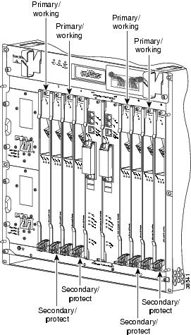
When you associate slots, the software pairs an odd-numbered slot with the next higher even-numbered slot:
•
Odd-numbered slot—Holds the primary card, or working card
•
Even-numbered slot—Holds the secondary card, or protect card
Figure 14-2 shows the redundant slot pairings in the Cisco 10008 chassis.
Figure 14-2 Redundant Slot Pairings in the Cisco 10008 Series Router
Note
Only slots 1 and 2 and slots 3 and 4 in the Cisco 10005 chassis can be used for APS redundancy because slot 5 does not have an associated higher, even-numbered slot.
This chapter describes the SR-APS feature in the following topics:
•
Feature History for SR-APS
•
Configuring SR-APS
•
Disabling SR-APS
•
Monitoring and Maintaining the SR-APS Configuration
•
Threshold Commands
Feature History for SR-APS
Cisco IOS Release
|
Description
|
Required PRE
|
12.0(21)ST
|
This feature was introduced on the Cisco 10000 series router.
|
PRE1
|
12.2(13)BZ
|
This feature was integrated into Cisco IOS Release 12.2(13)BZ
|
PRE1
|
12.3(7)XI
|
This feature was integrated into Cisco IOS Release 12.3(7)XI.
|
PRE2
|
12.2(28)SB
|
This feature was integrated into Cisco IOS Release 12.2(28)SB.
|
PRE2
|
Configuring SR-APS
To configure SR-APS, enter the following commands beginning in global configuration mode:
|
Command
|
Purpose
|
Step 1
|
Router(config)# redundancy
|
Enters redundancy configuration mode, which allows you to associate two line cards as a redundant pair.
|
Step 2
|
Router(config-r)# associate slot odd-slot
even-slot
|
Associates two line cards as a redundant pair.
To allow SR-APS to operate, you must specify a line card installed in an odd slot number as the first member of a redundant pair; the second line card must be installed in the even-numbered slot to its right.
|
Step 3
|
Router(config-r)# exit
|
Exits redundancy configuration mode and returns to global configuration mode.
|
Note
After you configure redundancy, the software treats the pair as though it occupies a single slot. The interface slot number is always the odd number of the redundant pair. For example, for the redundant pair occupying slots 5 and 6, the show interface pos 5/0/0 command refers to the active card (even if the active card occupies slot 6).
Disabling SR-APS
To disable SR-APS redundant operation, use the no form of the associate slot command. For example:
Router(config-r)# no associate slot 3 4
If the redundant configuration is disabled, the software modifies the running configuration in the following ways:
1.
The software removes all SR-APS configuration information.
2.
The software creates two configurations, one for the primary card and one for the protect card.
Table 14-1 shows examples of configuration files with redundancy enabled and disabled.
Table 14-1 Configuration File—Redundancy Enabled and Disabled
Redundancy Enabled
|
Redundancy Disabled
|
ip address 5.5.5.5 255.255.255.0
aps mode linear 1+1 nonreverting
unidirectional
aps signal-fail BER threshold 3
aps signal-degrade BER threshold 5
|
ip address 5.5.5.5 255.255.255.0
ip address 6.6.6.6 255.255.255.0
|
Monitoring and Maintaining the SR-APS Configuration
To monitor and maintain the configuration of SR-APS, enter any of the following commands in privileged EXEC mode:
Command
|
Purpose
|
Router# show aps
|
Displays the status of the APS-configured slot.
|
Router# aps clear [POS | SONET]
slot#/subslot#/port#
|
Clears the SR-APS commands on a channel and enables automatic SR-APS switching.
|
Router# aps force [POS | SONET]
slot#/subslot#/port# from [working | protection]
|
Forces a switch from the working channel to the protection channel, or from the protection channel to the working channel.
from working—Forces a switch from the working channel to the protection channel.
Note This command has no effect if the protection channel is currently the active channel.
from protection—Forces a switch from the protection channel to the working channel.
Note This command has no effect if the working channel is currently the active channel.
|
Router# aps lockout [POS | SONET]
slot#/subslot#/port#
|
Prevents a channel from automatically switching to the active, working, or protection state.
|
Router# aps manual [POS | SONET]
slot#/subslot#/port# from [working | protection]
|
Manually switches from the working channel to the protection channel, or from the protection channel to the working channel.
from working—Manually switches from the working channel to the protection channel.
Note This command has no effect if the protection channel is currently the active channel.
from protection—Manually switches from the protection channel to the working channel.
Note This command has no effect if the working channel is currently the active channel.
|
Example 14-3 Clearing SR-APS Commands on a Channel
Example 14-3 shows how to clear SR-APS commands on redundant Channelized OC-12 POS cards in slots 5 and 6:
Router# aps clear pos 5/0/0
Example 14-4 Forcing a SR-APS Switch
Example 14-4 shows how to force a switch from the working channel to the protection channel:
Router# aps force POS 5/0/0 from working
Example 14-5 Performing a Manual SR-APS Switch
Example 14-5 show how to manually switch the active channel from the working channel to the protection channel:
Router# aps manual POS 5/0/0 from working
Threshold Commands
Threshold commands allow you to specify criteria that trigger a cutover. In addition to the criteria set by these commands, cutovers are triggered by Section Loss of Signal (SLOS) critical alarms, Section Loss of Frame (SLOF) critical alarms, and Line Alarm Indicate Signal (LAIS) major alarms.
Specifying SR-APS Signal Degrade BER Threshold
Use the aps signal-degrade BER threshold command to modify the bit error rate threshold that, if exceeded, triggers an APS cutover.
aps signal-degrade BER threshold value
Where value can be in the range of 10-5 to 10-9. Enter this value as a single digit between 5 and 9.
The default signal degrade BER threshold value is 10-6.
Use the no form of the command to return the threshold value to its default.
In the following example, the threshold value is set to 10-8.
Router(config)# interface pos 8/0/0
Router(config-if)# aps signal-degrade BER threshold 8
Specifying SR-APS Signal Fail BER Threshold
Use the aps signal-fail BER threshold command to modify the bit error rate threshold that, if exceeded, causes an APS cutover.
aps signal-fail BER threshold value
Where value can be in the range of 10-3 to 10-5. Enter this value as a single digit between 3 and 5.
The default signal fail BER threshold value is 10-3.
Use the no form of the command to return the threshold value to its default.
In the following example, the threshold value is set to 10-4:
Router(config)# interface pos 8/0/0
Router(config-if)# aps signal-fail BER threshold 4