Feedback
Table Of Contents
Using Cisco ANA PathTracer to Diagnose Problems
Cisco ANA PathTracer Multipath Window
Cisco ANA PathTracer Multipath Window Toolbar
Cisco ANA PathTracer Multipath Window Menus
Cisco ANA PathTracer Single-Path Window
Cisco ANA PathTracer Single-Path Window Toolbar
Cisco ANA PathTracer Single-Path Window Menus
Properties Table and Layer Tabs
Saving and Opening Cisco ANA PathTracer Map Files
Saving Cisco ANA PathTracer Counter Values
Rerunning a Path and Making a Comparison
Using Cisco ANA PathTracer to Diagnose Problems
Cisco ANA enables you to view a network path between two network objects using Cisco ANA PathTracer:
•
In a circuit-switched network, such as Frame Relay or ATM, or
•
These topics describe the Cisco ANA PathTracer working environment and the functionality available when using Cisco ANA PathTracer:
•
•
•
•
•
•
•
•
•
•
Cisco ANA PathTracer Overview
Cisco ANA PathTracer enables end-to-end route tracing to be performed with informative performance information displayed simultaneously for the multiple networking layers. Upon receiving a path's start and endpoint, Cisco ANA PathTracer visually traces the route through the network. For example, in an ATM network environment, Cisco ANA PathTracer identifies all information regarding the connection of a subscriber to a provider, including all ATM PVCs, ATM switching tables, ATM class of service (CoS) definitions, IP-related information, and so on.
Cisco ANA understands and is able to derive the various paths on the network due to the up-to-date knowledge of the network. Cisco ANA PathTracer finds and retrieves the path of a specified service, after the user has selected a source and destination. The retrieved information contains network elements in the path, including all properties at Layer 1, Layer 2, and Layer 3, plus alarm information, counters, and more.
Cisco ANA PathTracer enables you to view multiple paths between the source and the destination in the Cisco ANA PathTracer multipath window, or to view a selected single-path in the Cisco ANA PathTracer single-path window.
Opening Cisco ANA PathTracer
Cisco ANA PathTracer can be opened from an ATM VC, DLCI, or from an IP interface entry point. The virtual route is found according to the Cross Connect table of each ATM switch or Frame Relay device. The IP routing and path finding process is enabled according to the VRF tables of each router.
To view a specific path, you must specify an initial point, such as a VPI/VCI, DLCI, Ethernet port or IP interface and (optionally) a destination IP address. If you specified VC information or DLCI information, which ends in a router, Cisco ANA PathTracer finds the next hop according to the destination IP address. If you did not specify the destination IP address, the system uses the default gateway in the router. In addition, the related business tags that have been referred to the physical or logical entities are also displayed.
Note
The Cisco ANA PathTracer tool provides the user with two windows in which to view the path:
•
•
You can also enter the required destination IP address after opening the Cisco ANA PathTracer from the right-click shortcut menu at one of the following locations:
To open Cisco ANA PathTracer:
Step 1
•
•
The Inventory window is displayed.
Step 2
•
•
Note
Step 3
Step 4
Note
Step 5
For more information about this window, see Cisco ANA PathTracer Single-Path Window.
For more information about opening the Cisco ANA PathTracer from other Cisco ANA NetworkVision windows, and about selecting multipath options, see the Cisco Active Network Abstraction 3.6.6 MPLS User Guide.
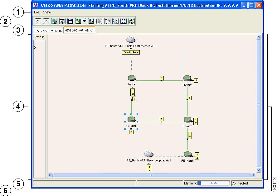
Cisco ANA PathTracer Multipath Window
The Cisco ANA PathTracer multipath window displays all the discovered paths for the selected context, including devices and physical links.
The Cisco ANA PathTracer multipath window enables you to perform the following functions:
•
•
•
•
An example of the Cisco ANA PathTracer multipath window is displayed in Figure 9-1.
Figure 9-1 Cisco ANA PathTracer Multipath Window
The Cisco ANA PathTracer multipath window is divided into the following areas:
•
•
•
Cisco ANA PathTracer Multipath Window Toolbar
The Cisco ANA PathTracer multipath window contains the following tools:
Selects the previous path viewed in the topological map pane.
Selects the next path viewed in the topological map pane.
Clears the path selection made in the topological map pane.
Opens the Cisco ANA PathTracer single-path window based on the path selected in the Cisco ANA PathTracer multipath window. A map is displayed for the selected path, including NE details, links and property information. For more information, see Cisco ANA PathTracer Single-Path Window.
Saves the multipath map displayed in the topological map pane. For more information, see Saving and Opening Cisco ANA PathTracer Map Files.
Defines the way in which the map is displayed in the topological map pane (circular, symmetric, tree, or hierarchical).
Opens a window displaying an overview of the network displayed in the topological map pane.
Runs Cisco ANA PathTracer again, creating a new map that is displayed in a topological map pane tab. A new tab with an up-to-date (refreshed) path map is created for each run (the source and destination must be the same), with each tab representing a run, and its header indicating the snapshot time.
For information about the selection tools displayed on the toolbar, see Cisco ANA NetworkVision Toolbar, page 2-17.
Cisco ANA PathTracer Multipath Window Menus
The File menu in the Cisco ANA PathTracer multipath window provides the following options:
•
•
•
In addition, you can right-click views and network elements in the multipath window and choose items from a shortcut menu. The shortcut menu is context sensitive depending on the view and the network element selected. For more information about the Device shortcut menu and for a detailed description of all the menu options available here, see Device Shortcut Menu, page 2-23.
Tabs
The path is initially displayed in the map pane in a tab that displays the starting point date and time at which Cisco ANA commenced the path tracing process (snapshot time).
If you want to load a saved path from a file or run the displayed path again, a new tab with an up-to-date (refreshed) path map is created for each run or file (the source and destination must be the same). This is displayed in a separate tab, with each tab representing a run or file, and its header indicating the snapshot time.
Paths Pane
The Paths pane displays all the paths available for the selected source and destination (for each source and destination pair, new path is created). The paths are displayed using numbers. Selecting a path in the Paths pane enables you to view each individual path in the map pane of the Cisco ANA PathTracer single-path window, and the selected path is highlighted in the map pane.
Map Pane
The map pane enables you to view a route map of the intermediate network elements. The map displays devices, links and paths (topological paths).
Icons are used in the map pane to display the network objects and these icons provide a visual representation of the network object's status. For more information about the icons used, see Appendix A, "Icon Reference".
All links and nodes are labeled with the relevant paths numbers. The starting point is labeled with a special Starting Point label. All other edge points are displayed as clouds.
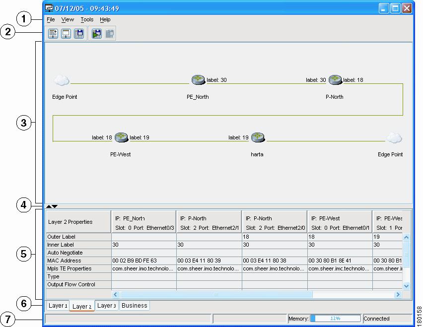
Cisco ANA PathTracer Single-Path Window
The Cisco ANA PathTracer single-path window displays the devices and links of the discovered path, as well as path layer properties and subscriber information.
Note
The Cisco ANA PathTracer single-path window enables you to:
•
•
–
–
–
•
•
In addition, right-clicking on an item in Cisco ANA PathTracer enables you to perform certain functions. For example, you can view device information, including device properties, and attach business tags.
An example of the Cisco ANA PathTracer single-path window is displayed.
Figure 9-2 Cisco ANA PathTracer Single-Path Window
Menu bar
Properties table
Toolbar
Layer tabs
Map pane
Status bar
Hide/Display Properties table
The Cisco ANA PathTracer single-path window is divided into the following areas:
•
•
•
Cisco ANA PathTracer Single-Path Window Toolbar
The Cisco ANA PathTracer single-path window contains the following tools:
Cisco ANA PathTracer Single-Path Window Menus
The following table n provides a description of each option available in the Cisco ANA PathTracer single-path window menus.
In addition, you can right-click views and network elements in the single-path window and choose items from a shortcut menu. The shortcut menu is context sensitive depending on the view and the network element selected. The following two Device shortcut menu options are available only from the single-path window:
•
•
Topological Map
The topological map displays the devices and links that are part of the path. Icons are used in Cisco ANA PathTracer to display the network objects and these icons provide a visual representation of the network object's status. For more information about the icons used, see Appendix A, "Icon Reference."
For more information about the colors used to indicate severities, see Map View, page 2-5.
The same coloring conventions that are used in the map pane of the Cisco ANA NetworkVision window are used to display links in the Cisco ANA PathTracer single-path window. Selecting a device or link on the map automatically highlights the related parameters in the table.
Note
There are three ways in which the status of a network object is indicated on the topological map:
1.
2.
3.
For more information, see Network Element Status Indicators, page 2-13.
Properties Table and Layer Tabs
The Properties table and tabs display the supported parameters of the specified NE. The Cisco ANA PathTracer single-path window is divided into tabs as shown in the example in Cisco ANA PathTracer Single-Path Window.
The information parameters are displayed in a table, with the ingress and egress ports on the top and the parameters on the left.
Any inconsistencies between the two connected ports are colored to emphasize a discrepancy, for example, different admin statuses.
The Cisco ANA PathTracer information parameters are arranged in groups as follows:
•
•
The Cisco ANA PathTracer window is divided into the following tabs and all appear empty when the window opens:
•
•
•
•
For specific information about VPN Cisco ANA PathTracer information, see the Cisco Active Network Abstraction 3.6.6 MPLS User Guide.
Viewing Path Information
The Cisco ANA PathTracer tabs display information regarding each network element, including ingress and egress port information. The information is either plain data that was extracted from the device or calculated data such as rates or statistics. This information is displayed in the Layer 1, Layer 2 and Layer 3 tabs of the Cisco ANA PathTracer single-path window.
To view path information, select the required tab, and click Show All. The path information is displayed in the active tab of the Cisco ANA PathTracer single-path window.
Note
Note
Saving and Opening Cisco ANA PathTracer Map Files
Cisco ANA NetworkVision enables you to export the maps (paths) displayed in the Cisco ANA PathTracer multipath window to an .xml file. The data can then be viewed at a later stage in order to assess whether anything has changed.
To save Cisco ANA PathTracer Map Files:
Step 1
Step 2
•
•
The Save dialog box is displayed.
Step 3
Step 4
Step 5
Cisco ANA NetworkVision enables you to open saved xml format path-tracing maps.
Note
•
To open Cisco ANA PathTracer Map Files:
Step 1
Step 2
Step 3
Saving Cisco ANA PathTracer Counter Values
Cisco ANA NetworkVision enables you to export the counter values of the path displayed in the Cisco ANA PathTracer single-path window to a CSV file. The data can then be viewed at a later stage.
Note
To save Cisco ANA PathTracer counter values:
Step 1
Step 2
•
•
The Export Table to File dialog box is displayed.
Step 3
Step 4
Step 5
You can then stop exporting the counter values of the path displayed in the Cisco ANA PathTracer single-path window to a CSV file.
To stop saving Cisco ANA PathTracer counter values, do one of the following:
•
•
Cisco ANA NetworkVision stops exporting the counter values to the CSV file.
Rerunning a Path and Making a Comparison
Cisco ANA NetworkVision enables you to save and load a path (see Saving and Opening Cisco ANA PathTracer Map Files). This file can then be used at a later stage to rerun the path automatically using the same source and destination. You can then compare the paths if, for example, you suspect that the path has changed, and assess where the problem is occurring.
To rerun the path:
Step 1
Step 2
•
•
The path reruns automatically using the same source and destination as the loaded map file and a new tab is displayed in the Cisco ANA PathTracer multipath window with the updated map (path). The tab also displays the updated details of the date and time when the path was rerun.
Step 3
Note
•
Viewing QinQ Path Information
The QinQ (IEEE802.1) tagging technology (also known as Dot1q tunneling) allows the nesting of an additional VLAN tag in a packet, in addition to an existing one. Either VLAN tag is considered an 802.1Q header.
Cisco ANA PathTracer uses the VLAN tags of the Ethernet header and the port configuration to trace the path from one interface to another over the network. Among other things, the tool lets you:
•
•
QinQ and Dot1q information is displayed in the Cisco ANA PathTracer windows when a path is traced over Ethernet ports with Dot1q and a QinQ configuration.
As explained in Opening Cisco ANA PathTracer, to view a specific path, you must specify an initial start point, such as an IP interface, and then an endpoint, such as a destination IP address.
To trace a QinQ path, you start the path from any:
•
•
Table 9-2 describes the starting points available in the shortcut menu when you open Cisco ANA PathTracer:
Table 9-2 Cisco ANA PathTracer Starting Points
IP Interface
Inventory window
•
•
If you select the Start Here option, the following endpoints can be selected as a path destination, which will then open the Cisco ANA PathTracer:
Table 9-3 Cisco ANA PathTracer Endpoints
IP Interface
Inventory window
End Here
As soon as you select the endpoint, the Cisco ANA PathTracer Multipath window is displayed (see Cisco ANA PathTracer Multipath Window). From this window, you can open the Cisco ANA PathTracer Single-Path window, with the appropriate QinQ information displayed in the Layer 2 tab (see Cisco ANA PathTracer Single-Path Window).
The Layer 2 tab can display the following information specific to QinQ and VLAN port configurations:
•
•
•
•
Viewing L2TP Path Information
Cisco ANA uses VC ID encapsulation information to trace the path from one tunnel interface to another over the network. The Cisco ANA PathTracer tool enables you to:
•
•
Layer 2 and Layer 3 L2TP information is displayed in the Cisco ANA PathTracer windows when a path is traced over L2TP tunnels for Redback devices.
The Layer 3 tab can display the following information specific to L2TP tunnels:
•
The Layer 2 tab can display the following information specific to L2TP tunnels: