Feedback
Table Of Contents
Working with Unmanaged Segments
Using Cloud VNEs over Unmanaged Segments
Supported Networking Technologies for Cloud VNEs
Cloud VNEs with ATM and Frame Relay Technologies
Cloud VNEs with Ethernet Technology
Important Notes About Ethernet Cloud VNE Configuration
Configuring Duplicate IP Addresses on Ethernet Interfaces
Identifying the Port Physical Layer OID
Modeling Multiple Access Networks with Cloud VNEs
Fault Correlation Across the Frame Relay, ATM, or Ethernet Cloud
Cloud Problem Alarm and Correlation Example
Working with Unmanaged Segments
These topics describe how Cisco ANA manages virtual (VNE) clouds that are used to represent unmanaged network segments, the technologies that support Cloud VNEs, how to model multiple access networks with Cloud VNEs, and how Cisco ANA performs correlation decisions over unmanaged segments:
•
Using Cloud VNEs over Unmanaged Segments—Describes how to manage more than one network segment that interconnects with others, over another network segment which is not managed.
•
•
•
•
Using Cloud VNEs over Unmanaged Segments
In some scenarios, Cisco ANA is required to manage more than one network segment that interconnects with others over a network segment which is not managed. In such a setup, faults on one device might be correlated to faults on another device which is located on the other side of the unmanaged segment of the network, or to unknown problems in the unmanaged segment itself.
Note
Cisco ANA uses Cloud VNEs to represent unmanaged network segments. A Cloud VNE represents the unmanaged segment of a network as a single device to which two or more managed segments of the network can be connected. The Cloud VNE builds a model with port type and technology that is identical to its adjacent VNEs and virtual forwarding components. This model allows the VNEs to pass flows of simulated packets in order to calculate correlations and affected subscribers.
Each VNE can be configured to connect to a Cloud VNE. When loading, the VNE gathers whatever data is relevant to the Cloud VNE, and sends the data to it. Upon receiving this information, the Cloud VNE builds the corresponding model to allow the topology to connect the two VNEs.
Note
A Cloud VNE can also represent multiple unmanaged segments and multiple technologies, as long as each technology is in a different network segment. In addition, multiple Cloud VNEs can also be created, each one representing a portion of an unmanaged network. For more information, see Modeling Multiple Access Networks with Cloud VNEs.
Three types of technologies are supported when a Cloud VNE simulates an unmanaged segment of a network: Frame Relay, ATM, and Ethernet. For more information about the supported technologies for Cloud VNEs, see Supported Networking Technologies for Cloud VNEs.
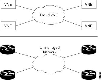
Figure 7-1 shows network elements (routers) that are connected to an unmanaged network, and their corresponding VNEs. The unmanaged segment represented by the Cloud VNE can be an ATM, Frame Relay, or Ethernet type network (Layer 2 only).
Figure 7-1 Cloud VNE Example
Supported Networking Technologies for Cloud VNEs
Three types of networking technologies are supported for Cloud VNEs—Frame Relay, ATM, and Ethernet—as described in the following topics:
•
•
Cloud VNEs with ATM and Frame Relay Technologies
The Cloud VNE can simulate an ATM or Frame Relay switching network, in which the endpoints are routers with ATM or Frame Relay interfaces that terminate the switching network.
The functionality of the Cloud VNE is similar to that of a virtual switch that connects endpoints that are part of the managed network. The Cloud VNE has an ATM (or Frame Relay) port for each VNE port connected to it. The cloud also contains forwarding information in a cross-connect table (with ATM VC encapsulation, or Frame Relay VC encapsulation with DLCI), that represents how traffic passes the unmanaged switching network.
The logic that builds the cross-connects in the Cloud VNE is based on one of the following:
•
•
Note
Cloud VNEs with Ethernet Technology
The Cloud VNE can simulate an Ethernet network with (optionally) multiple VLANs configured, in which the endpoints are either routers with Ethernet interfaces, or LAN switches.
The functionality of the Cloud VNE is similar to that of a virtual LAN switch that connects endpoints that are part of the managed network. The Cloud VNE contains an Ethernet port with all VLAN encapsulations for each VNE port connected to it. It also contains forwarding information in a per-VLAN bridging table that represents how traffic passes through the unmanaged network.
The logic that builds the bridging tables in the Cloud VNE is based on Ethernet layer information, as follows:
•
–
–
•
Important Notes About Ethernet Cloud VNE Configuration
When using an Ethernet LAN cloud to represent unmanaged network segments, be aware of the following:
•
•
•
•
•
•
•
•
•
Configuring Duplicate IP Addresses on Ethernet Interfaces
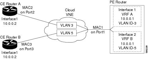
Figure 7-2 provides an example of a configuration of duplicate IP addresses on Ethernet interfaces that are connected to the same Cloud VNE.
Figure 7-2 Duplicate IP Addresses on Ethernet Interfaces
In Figure 7-2, a PE router and two CEs are connected to an unmanaged Ethernet access network, represented by a Cloud VNE.
The PE router is connected to the Cloud VNE through Port1. Two interfaces configured on Port1 are connected to different VRFs (VRF A and VRF B). Both VRF interfaces are configured with the same IP address (10.0.0.1). Each interface is configured with a different VLAN encapsulation (VLAN-ID 3 and VLAN-ID 5), and is connected to a different VLAN in the unmanaged network (VLAN 3 and VLAN 5).
The two CEs are connected to different VLANs in the unmanaged network: CE A is connected to VLAN 3 through Port2, and CE B is connected to VLAN 5 through Port3. Both Port2 and Port3 are access ports (that is, untagged ports with no VLAN encapsulation) and are configured with identical IP addresses (10.0.0.2).
The Cloud VNE creates a similar port for each port connected to it, and two bridges, one per VLAN (that is, a bridge for VLAN 3 and a bridge for VLAN 5). Each bridge contains a forwarding table with the MAC addresses of the ports connected to that VLAN. In this example, the bridge representing VLAN 3 contains MAC1 and MAC2, and the bridge representing VLAN 5 contains MAC1 and MAC3.
Cloud VNE Setup in Cisco ANA
The creation and setup of Cloud VNEs is done using Cisco ANA Manage and the command line interface. Each Cloud VNE must have a unique IP address (to be used as the Cloud VNE's internal address) that cannot be used to access any network element. To connect a regular VNE to a Cloud VNE, the VNE must be configured with the physical port that should be connected, and the IP address of the Cloud VNE.
For a full description of how to add and define a VNE using Cisco ANA Manage, refer to "Defining VNEs" in Chapter 6 of the Cisco Active Network Abstraction 3.6.6 Administrator Guide.
Note
Before you begin to set up a Cloud VNE, make sure the following prerequisites have been met:
•
•
•
•
The following procedure describes how to create a Cloud VNE:
Step 1
Step 2
Step 3
•
•
•
The New VNE dialog box opens.
Step 4
a.
b.
c.
Note
Note
d.
Step 5
Dynamic Cloud VNE Setup
When configuring a Cloud VNE for dynamic operation, the cloud model and the topology (that is, the link between the cloud VNE and the adjacent VNE) are discovered and managed automatically by Cisco ANA.
To configure the Cloud VNE to operate dynamically, after creating a new VNE with a unique IP address, you must:
•
•
The following describes how to do this.
1.
For each VNE that represents a device that is connected to the unmanaged network represented by the Cloud VNE, do the following:
a.
b.
c.
# ./runRegTool.sh -gs 127.0.0.1 add <server-ip>
"avm<avm-id>/agents/da/<vne-name>/dcs/instance/<physical-layer-oid>/cloud
topology"
# ./runRegTool.sh -gs 127.0.0.1 set <server-ip> "avm<avm-id>/agents/da/<vne-name>/dcs/instance/<physical-layer-oid>/cloud topology/address" <cloud-address>The following lists the parameters you must define:
server-ip
The IP address of the UNIX machine of the unit or gateway on which the AVM (the AVM of the VNE connected to the Cloud VNE) resides.
avm-id
The ID of the AVM on which the VNE connected to the Cloud VNE is configured.
vne-name
The name of the VNE which is connected to the Cloud VNE.
physical-layer-oid
The OID of the port on the VNE which should be connected to the Cloud VNE (see Identifying the Port Physical Layer OID for instructions on how to find this OID).
cloud-address
The IP address of the Cloud VNE (see Cloud VNE Setup in Cisco ANA).
Note
Any forward slash character ("/") in the <physical-layer-oid> is changed into the string "\!slash\!" when using the CLI.For example, the following commands configure the physical layer with OID {[ManagedElement(Key=PE_South)][PhysicalRoot][Chassis][Slot(SlotNum=1)][Module][Port(PortNumber=FastEthernet1/0)][PhysicalLayer]}, on VNE PE_South which resides in avm900 on unit 192.168.100.1, to connect to the Cloud VNE with address 1.2.3.4:
./runRegTool.sh -gs 127.0.0.1 add 192.168.100.1
"avm900/agents/da/PE_South/dcs/instance/{[ManagedElement(Key=PE_South)][PhysicalRo
ot][Chassis][Slot(SlotNum=1)][Module][Port(PortNumber=FastEthernet1\!slash\!0)][Ph
ysicalLayer]}/cloud topology"
./runRegTool.sh -gs 127.0.0.1 set 192.168.100.1 "avm900/agents/da/PE_South/dcs/instance/{[ManagedElement(Key=PE_South)][PhysicalRo ot][Chassis][Slot(SlotNum=1)][Module][Port(PortNumber=FastEthernet1\!slash\!0)][Ph ysicalLayer]}/cloud topology/address" 1.2.3.42.
If the cloud is an Ethernet type, you must configure the permissible subnets that enable the IP interfaces that are part of the subnets to connect to the cloud. This configuration minimizes the number of connections the Cloud VNE handles, because only connections to and from IP addresses within those subnets are handled.
Note
•
For each Cloud VNE, do the following:
a.
b.
# ./runRegTool.sh -gs 127.0.0.1 add <server-ip>
"avm<avm-id>/agents/da/<cloud-vne-name>/amsi/topology/dynamic/permissible-subnet"
# ./runRegTool.sh -gs 127.0.0.1 set <server-ip> "avm<avm-id>/agents/da/<cloud-vne-name>/amsi/topology/dynamic/permissible-subnet/s ubnet" <permissible-subnet>The following lists the parameters you must define:
server-ip
The IP address of the UNIX machine of the unit or gateway on which the AVM (the AVM of the VNE connected to the Cloud VNE) resides.
avm-id
The ID of the AVM on which the VNE connected to the Cloud VNE is configured.
cloud-vne-name
The name of the Cloud VNE (as defined in Cloud VNE Setup in Cisco ANA).
permissible-subnet
The permissible subnet in the format address/mask (such as 192.168.1.0/24).
Note
You can add multiple subnets by running the second CLI command multiple times. Each entry has a different name (e.g., "subnet-2", "subnet-3", and so on).For example, the following commands configure the permissible subnet 0.0.0.0/0 (which means that connection from any address is handled), on Cloud VNE EthernetCloud which resides in avm900 on unit 192.168.100.1:
# ./runRegTool.sh -gs 127.0.0.1 add 192.168.100.1
"avm900/agents/da/EthernetCloud/amsi/topology/dynamic/permissible-subnet"
./runRegTool.sh -gs 127.0.0.1 set 192.168.100.1 "avm900/agents/da/EthernetCloud/amsi/topology/dynamic/permissible-subnet/subnet" 0.0.0.0/03.
Identifying the Port Physical Layer OID
The following procedure describes how to find the physical port layer OID of the cloud-facing port:
Step 1
The following is an example of an optimized GET command for VNE PE_South:
<command name="Get"><param name="oid"><value>{[ManagedElement(Key=PE_South)][PhysicalRoot]}</value></param><param name="rs"><value><key name="imo-view-controller"><entry name="depth">10</entry><entry name="register">true</entry><entry name="cachedResultAcceptable">false</entry><key name="requiredProperties"><key name="com.sheer.imo.IPhysicalRoot"><entry name="EquipmentHolders"/></key><key name="com.sheer.imo.IEquipmentHolder"><entry name="ContainedEquipmentHolder"/><entry name="ContainedEquipment"/></key><key name="com.sheer.imo.IEquipment"><entry name="SupportedPTPs"/></key><key name="com.sheer.imo.IPhysicalTerminationPoint"><entry name="ContainedCurrentCTPs"/></key></key><key name="requiredAspects"></key></key></value></param></command>Step 2
<?xml version="1.0" encoding="UTF-8"?><IPhysicalRoot><ID type="Oid">{[ManagedElement(Key=PE_South)][PhysicalRoot]}</ID><EquipmentHolders type="IMObjects_Array"><IChassis><ID type="Oid">{[ManagedElement(Key=PE_South)][PhysicalRoot][Chassis]}</ID><ContainedEquipmentHolder type="IMObjects_Array">....<IEquipmentHolder><ID type="Oid">{[ManagedElement(Key=PE_South)][PhysicalRoot][Chassis][Slot(SlotNum=1)]}</I D><ContainedEquipment type="IModule"><ID type="Oid">{[ManagedElement(Key=PE_South)][PhysicalRoot][Chassis][Slot(SlotNum=1)][Mod ule]}</ID><SupportedPTPs type="IMObjects_Array"><IPortConnector><ID type="Oid">{[ManagedElement(Key=PE_South)][PhysicalRoot][Chassis][Slot(SlotNum=1)][Mod ule][Port(PortNumber=FastEthernet1/1)]}</ID><ContainedCurrentCTPs type="IMObjects_Array"><IPhysicalLayer><ID type="Oid">{[ManagedElement(Key=PE_South)][PhysicalRoot][Chassis][Slot(SlotNum=1)][Mod ule][Port(PortNumber=FastEthernet1/1)][PhysicalLayer]}</ID></IPhysicalLayer></ContainedCurrentCTPs></IPortConnector><IPortConnector><ID type="Oid">{[ManagedElement(Key=PE_South)][PhysicalRoot][Chassis][Slot(SlotNum=1)][Mod ule][Port(PortNumber=FastEthernet1/0)]}</ID><ContainedCurrentCTPs type="IMObjects_Array"><IPhysicalLayer><ID type="Oid">{[ManagedElement(Key=PE_South)][PhysicalRoot][Chassis][Slot(SlotNum=1)][Mod ule][Port(PortNumber=FastEthernet1/0)][PhysicalLayer]}</ID></IPhysicalLayer></ContainedCurrentCTPs></IPortConnector></SupportedPTPs></ContainedEquipment></IEquipmentHolder>....</ContainedEquipmentHolder></IChassis></EquipmentHolders></IPhysicalRoot>The OID is {[ManagedElement(Key=PE_South)][PhysicalRoot][Chassis][Slot(SlotNum=1)][Module][Port(PortNumber=FastEthernet1/0)][PhysicalLayer]}
Step 3
For example, the OID should be changed to:
{[ManagedElement(Key=PE_South)][PhysicalRoot][Chassis][Slot(SlotNum=1)][Module][Port(PortNumber=FastEthernet1\!slash\!0)][PhysicalLayer]}
Modeling Multiple Access Networks with Cloud VNEs
In most scenarios, unmanaged network segments are access networks that are used by customers to access the service provider network. Legacy access networks are based on circuit switching such as ATM and Frame Relay, while new access networks are mainly Ethernet based.
In multiple separated access networks, it is common practice to create multiple Cloud VNEs, one per access network.
This type of configuration has the following advantages:
•
•
•
Fault Correlation Across the Frame Relay, ATM, or Ethernet Cloud
When a Layer 3 or Layer 2 event (for example, reachability problem, neighbor change, Frame Relay DLCI down, ATM PVC down) occurs, it triggers a flow along the physical and logical path modeled on the VNEs. This is done in order to correlate to the actual root cause of this fault. If the flow passes over a cloud along the path flow, it marks it as a potential root cause for the fault. If there is no other root cause found on the managed devices, then the cloud becomes the root cause. A ticket is then issued and the original event correlates to it.
Cloud Problem Alarm and Correlation Example
For some events, when there is no root cause found, a special Cloud Problem alarm is created. These events are then correlated to the alarm. If several events trigger the creation of a Cloud Problem alarm, one alarm instance is created and all events correlate to it.
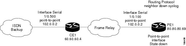
In the example in Figure 7-3, two devices that have OSPF configured are connected through a cloud. A malfunction occurs inside the unmanaged network that causes the OPSF Neighbor Down alarm to be generated. In this case, the OSPF neighbor down alarm is correlated to the Cloud Problem.
Figure 7-3 Cloud Correlation Example
On the PE1 device, the OSPF neighbor down alarm was received, and no root cause was detected in any of the managed devices. A disconnected link inside the unmanaged network caused the OSPF neighbor down alarm. The Cloud Problem service alarm is generated, and the OSPF neighbor down on the PE1 is correlated to the Cloud Problem alarm.
For more information about the Cloud Problem alarm, see Cloud Problem, page 16-10.