Feedback
Table Of Contents
Understanding Dynamic and Static Links
Suppressing Link Alarms Using the Link Maintenance State
Viewing Links and their Properties with the Links View
Filtering Links Using the Collection Method
Working with Links
These topics describe how to view information about static and dynamic links using the Cisco ANA NetworkVision user interface:
•
Understanding Dynamic and Static Links, describes the differences between dynamic and static links.
•
•
•
•
•
•
For information on viewing link properties from the map view (for example, link tooltip information), see Map View, page 2-5.
Understanding Dynamic and Static Links
Cisco ANA NetworkVision provides a topological model of the physical and logical links that exist between elements in the network. Cisco ANA automatically discovers these links, and the ongoing process of autodiscovery maintains this topological information. Cisco ANA NetworkVision discovers any new links that are added and continues to verify that the discovered links still exist; for this reason, they are called dynamic links.
Property information is provided for links that are:
•
•
•
If a link is unidirectional, Cisco ANA NetworkVision displays an arrowhead on the link. If it is bidirectional, an arrowhead is not displayed.
Cisco ANA NetworkVision also provides functionality that allows you to create links on the VNE level. These links do not perform any configuration or provisioning on a device or in the network. Because the links do not really exist in the network, the links are not updated. For this reason they are called static links. Static links are useful for map visualization and network correlation; for example, if Cisco ANA does not discover a link that you know exists in the network, you can create a static link that is displayed in the map. For correlation purposes, Cisco ANA treats the static link as if it were a physical or logical link and allows correlation flows to go through the static link. For information on how to create static links, see Adding Static Links.
You can identify whether a link is static or dynamic by looking at the link properties, as described in Opening Link Properties. In addition, the links displayed in the map pane have tooltips that provide you with a short link description. Physical links are highlighted in bold. The links displayed in the map pane can be filtered. For more information, see Filtering Links According to Type, page 8-17.
Opening Link Properties
The properties of the physical links between two ports are viewed using the link properties window. Cisco ANA supports links for technologies such as ATM, Frame Relay, Ethernet, and Serial.
Note
To open link properties:
Step 1
Step 2
•
•
The link properties window is displayed.
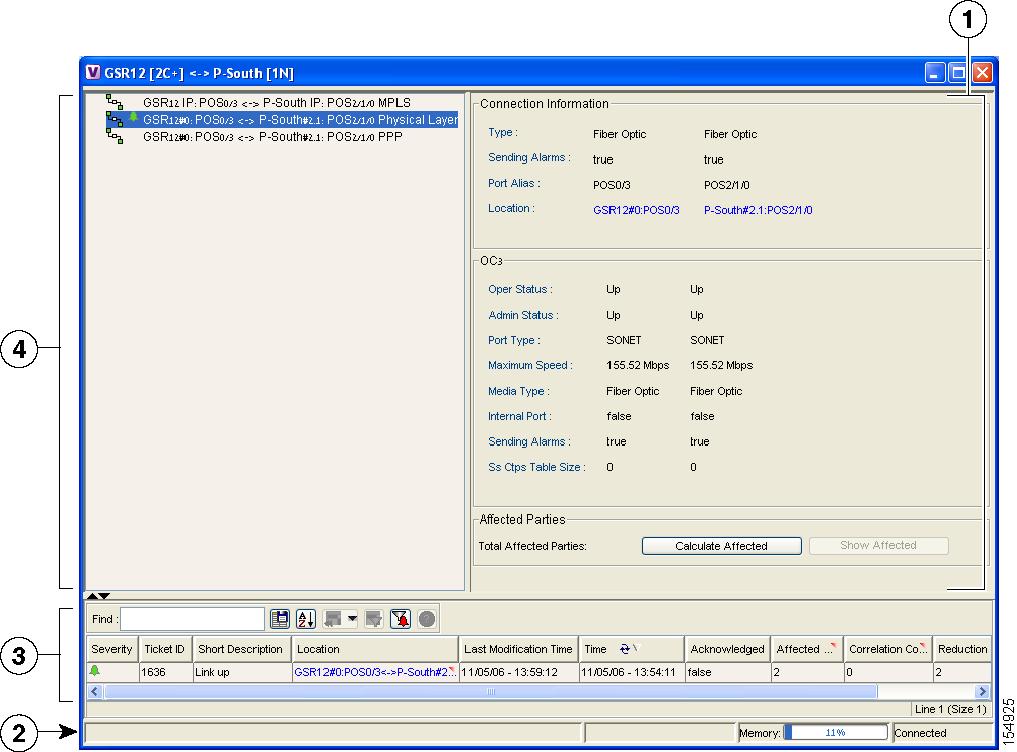
Figure 14-1 Link Properties Window
Note
Step 3
Monitoring Link Properties
The link properties window is divided into the following areas:
All the areas displayed in the link properties window are correlated; this means that selecting an option in one area affects the information displayed in the other areas.
The information displayed in the link properties window changes according to the ports or sub-ports selected in the Link List pane.
Link List Pane
The Link List pane displays a list of the links that are represented by a single link on the map. Each link has a single entry in the Link List pane.
When a branch is selected in the Link List pane, the information displayed in the properties pane is updated. The color of the icon in the Link List pane reflects its severity. For more information about severity, see Network Element Status Indicators, page 2-13.
The heading and the Link List pane display the left and right link identifiers between the two nodes, the device alias and CTP.
Properties Pane
The properties pane enables you to view the following, depending on your selection in the Link List pane:
•
•
•
The properties pane displays the connection information type, port alias and port location (a hyperlink), all of which uniquely identify the port. The port location information is also displayed as a hyperlink to the Inventory window.
The properties pane displays the parameters for the different sides of the link, aligned under the relevant link identifier. Any discrepancies between the link's ports are colored red.
The properties pane enables you to view the statistics of the traffic on the link. The following fields are displayed in the Connection Information area:
•
•
•
•
The following fields may be displayed in the properties pane:
•
•
•
•
•
•
•
The following buttons are displayed in the Affected Parties area for physical links:
•
Note
•
Note
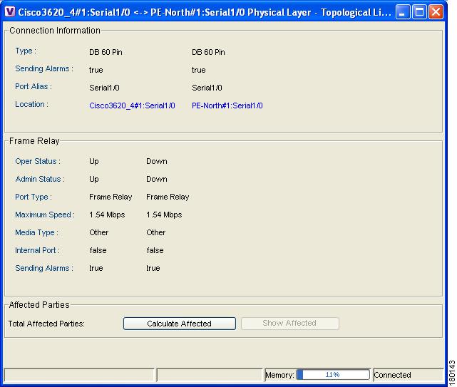
Viewing Link Impact Analysis
Cisco ANA NetworkVision enables the user to select a network link and calculate the parties that would potentially be affected if the link went down. This enables you to perform proactive impact analysis when a fault has not actually occurred.
Note
To calculate impact analysis:
Step 1
Step 2
Step 3
Step 4
Figure 14-2 Topological Link Properties Window
Step 5
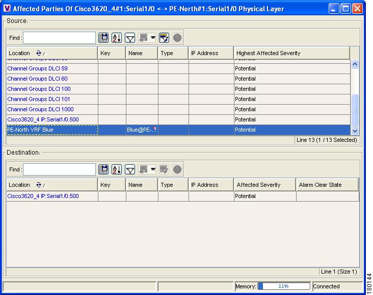
Step 6
Figure 14-3 Affected Parties Dialog Box
Step 7
Adding Static Links
Cisco ANA NetworkVision provides a user interface that allows you to create static links, which exist only on the VNE level. Static links are useful for visualization and network correlation because Cisco ANA allows correlation flows to go through the links, as if they were real physical or logical links. Static link properties are not updated because the links do not really exist in the network.
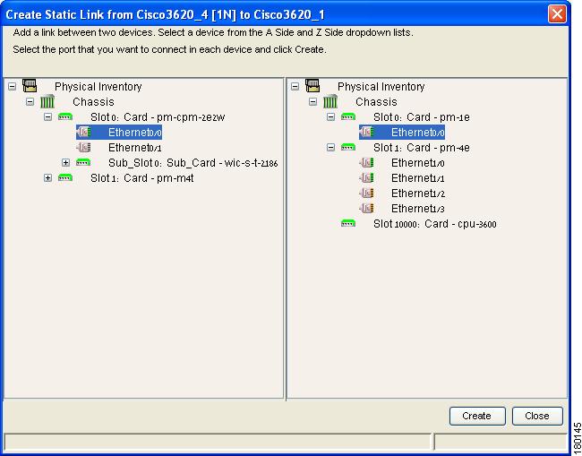
To create a static link, select a device or port and define it as the A side. Then define a second device or port as the Z side. Cisco ANA validates the new link after the two ports are selected. Validation checks the consistency of the port types (for example, RJ45 on both sides), and Layer 2 technology type (for example, ATM OC-3 on both sides).
When adding a new link, the color of the link reflects its current state. For example, if the operation status of a port is down, the link is colored red. You can add links from either the Cisco ANA NetworkVision window's tree and map pane (method 1), or from the Inventory window tree pane (method 2).
In addition, you can add a new link using Cisco ANA Manage. For more information, see the Cisco Active Network Abstraction 3.6.6 Administrator Guide.
Adding a Link (Method 1)
Step 1
Step 2
Figure 14-4 Create Static Link Dialog Box
Step 3
Step 4
Note
•
•
•
•
•
Step 5
Step 6
Adding a Link (Method 2)
Step 1
Note
Step 2
Step 3
Step 4
Step 5
Step 6
Note
•
•
•
•
•
Step 7
For information about removing a static link, see the Cisco Active Network Abstraction 3.6.6 Administrator Guide.
Suppressing Link Alarms Using the Link Maintenance State
To suppress alarms generated by a link, you can place the link in maintenance mode. This is useful when you want to add business links and perform provisioning before you make the links operational. When a link is in the maintenance state, Cisco ANA does not report any alarms on the link or process traps or syslogs that might affect the link (similar to when a VNE is in the maintenance state). By default, alarms generated by links in maintenance mode are not displayed in Cisco ANA EventVision, but you can change this setting; see Selecting Cisco ANA EventVision Viewing Options, page 3-6.
Placing a link in the maintenance state does not affect the management state of the overall VNE.
In Cisco ANA NetworkVision, you can change the mode of links from the links view or the links properties window. To identify map links that are currently in the maintenance state, open the links view as described in Viewing Links and their Properties with the Links View.
Note
Step 1
Step 2
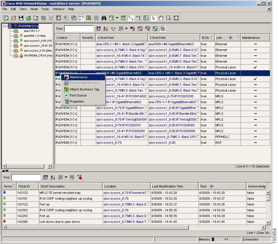
Figure 14-5 Maintenance Mode Information in the Links View
Step 3
Viewing Links and their Properties with the Links View
The links view provides you with an easy way to access a tabular list of the types of physical links displayed on the map (the links shown in the map pane are a summary of the many links starting from one side and ending at the other side of the link) and their status.
Note
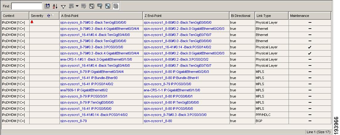
To display the links view in the Cisco ANA NetworkVision window, click the Show Links View icon in the main toolbar. Figure 14-6 provides an example of a links view.
Figure 14-6 Links View
Note
Any links that are added or removed from the map are automatically added or removed from the links view, provided they have not been filtered out.
The links view displays the selected filtered links and the new location in the tree pane:
•
•
The following columns are displayed in the links view:
•
•
•
•
•
•
•
Note
•
The links displayed in the links view are by default sorted according to link type and the deep collection method. In addition, the links view can be sorted:
•
icon is displayed next to the selected column heading.
•
The Location field displays the number of selected rows and the total number of rows in the table, for example, 2/16 Selected. In addition, it displays the location of the selected rows in the table, for example, Line 3.
The Find field enables you to search for information in the links view table according to the selected column.
For more information about the standard buttons displayed in Cisco ANA NetworkVision tables and table functionality, see Opening a New Map from the Map List Dialog Box, page 8-3.
The following additional buttons are displayed at the top of the links view and enable you to filter the links using the collection method:
For more information about filtering links using the collection method, see Filtering Links Using the Collection Method.
Some of the functions that can be performed in the links view are:
•
•
•
•
•
Filtering Links Using the Collection Method
The links view table is a very powerful tool allowing you to "view" NEs links that you cannot see visually or graphically in the map pane in the Cisco ANA NetworkVision window's workspace. The links view table is dynamic and automatically refreshes itself, allowing you to view up-to-date network links in real time.
The collection method enables you to filter the links displayed in the links view based on the selected context (map or aggregated node). By selecting the collection method from the toolbar in the links view table, the user can quickly filter the links.
Note
•
For more information about the buttons displayed in the links view, see Viewing Links and their Properties with the Links View.
For more information about filtering links according to type, see Filtering Links According to Type, page 8-17.
To filter links according to the collection method:
Step 1
Step 2
Step 3
•
•
•
•
The links are displayed in the links view according to the defined collection method.
Cisco ANA NetworkVision also enables you to find the source of a link displayed in the links view by highlighting the link in the map pane.
To find the link source:
Step 1
Step 2
Note
Note