-
Cisco Prime Network User Guide, 3.9
-
Preface
-
Cisco Prime Network Client Overview
-
Working with the Cisco Prime Network Vision Client
-
Viewing Network Element Properties
-
Working with Prime Network Vision Maps
-
Working with Links
-
Working with Business Tags and Business Elements
-
Working with the Prime Network Events Client
-
Tracking Faults Using Prime Network Events
-
Working with Tickets in Cisco Prime Network Vision
-
Working with Reports
-
Using Cisco PathTracer to Diagnose Problems
-
Monitoring Carrier Ethernet Services
-
Monitoring Carrier Grade NAT Properties
-
Monitoring DWDM Properties
-
Viewing Ethernet Operations, Administration, and Maintenance Tool Properties
-
IPv6 and IPv6 VPN over MPLS
-
Monitoring MPLS Services
-
Monitoring MToP Services
-
Viewing SBC Properties
-
Viewing Mobile Technologies in Prime Network
-
Icon and Button Reference
-
Index
-
 Feedback
Table Of Contents
Working with Prime Network Vision Maps
User Roles Required for Working with Prime Network Vision Maps
Opening Previously Viewed Maps
Opening a Map from the Open Map Dialog Box
Working with Elements in a Map
Deleting a Map from the Prime Network Vision Database
Finding a Network Element or Service
Finding and Selecting Links in Maps
Finding Elements Affected by a Ticket
Grouping Network Elements into Aggregations
Adding Elements to an Existing Aggregation
Viewing an Aggregation Thumbnail
Filtering Links During Map Creation
Filtering Links in an Existing Map
Communicating with Devices Using Ping and Telnet
Working with Prime Network Vision Maps
The topological map is the main tool used by Cisco Prime Network Vision (Prime Network Vision) to display the links and relationships between the network elements and aggregations. The following topics describe how to work with the topological maps displayed in the content pane of the Prime Network Vision window:
•
User Roles Required for Working with Prime Network Vision Maps
•
•
You can also perform the following functions from the map and list views if they are configured for your client:
•
•
For more information on these functions, see the Cisco Prime Network 3.9 Customization User Guide.
User Roles Required for Working with Prime Network Vision Maps
This topic identifies the roles that are required to work with Prime Network Vision maps. Prime Network determines whether you are authorized to perform a task as follows:
•
•
For more information on user authorization, see the Cisco Prime Network 3.9 Administrator Guide.
The following tables identify the tasks that you can perform:
•
•
By default, users with the Administrator role have access to all managed elements. To change the Administrator user scope, see the topic on device scopes in the Cisco Prime Network 3.9 Administrator Guide.
Table 4-1 Default Permission/Security Level Required for Working with Prime Network Vision Maps - Element Not in User's Scope
Apply a background image
—
—
—
X
X
Create maps
—
—
X
X
X
Define a map layout
X
X
X
X
X
Delete maps
—
—
X
X
X
Open maps
X
X
X
X
X
Preview and print maps
X
X
X
X
X
Rename maps
—
—
X
X
X
Save as a new map
—
—
X
X
X
Save as an image
X
X
X
X
X
Save map appearance
—
—
X
X
X
Select viewing options
X
X
X
X
X
Use Overview window
X
X
X
X
X
View maps
X
X
X
X
X
Add elements to a map
—
—
X
X
X
Remove elements from a map
—
—
X
X
X
Resize elements in a map
X
X
X
X
X
Group and ungroup aggregations
—
—
X
X
X
Rename aggregations
X
X
X
X
X
View aggregation thumbnails
X
X
X
X
X
Find affected elements
—
—
—
—
X
Find an element or service
X
X
X
X
X
Find and select a link in a map1
X
X
X
X
X
Filter links
X
X
X
X
X
Apply an overlay
X
X
X
X
X
Hide or view an overlay
X
X
X
X
X
Remove an overlay
X
X
X
X
X
Open the CPU Usage Graph
—
—
—
—
X
Use Ping and Telnet to communicate with elements
—
—
—
—
X
1 This applies to links within the selected context, and not links identified as network links.
Table 4-2 Default Permission/Security Level Required for Working with Prime Network Vision Maps - Element in User's Scope
Apply a background image
—
—
—
X
X
Create maps
—
—
X
X
X
Define a map layout
X
X
X
X
X
Delete maps
—
—
X
X
X
Open maps
X
X
X
X
X
Preview and print maps
X
X
X
X
X
Rename maps
—
—
X
X
X
Save as a new map
—
—
X
X
X
Save as an image
X
X
X
X
X
Save map appearance
—
—
X
X
X
Select viewing options
X
X
X
X
X
Use Overview window
X
X
X
X
X
View maps
X
X
X
X
X
Add elements to a map
—
—
X
X
X
Remove elements from a map
—
—
X
X
X
Resize elements in a map
X
X
X
X
X
Group and ungroup aggregations
—
—
X
X
X
Rename aggregations
X
X
X
X
X
View aggregation thumbnails
X
X
X
X
X
Find affected elements
X
X
X
X
X
Find an element or service
X
X
X
X
X
Find and select a link in a map1
X
X
X
X
X
Filter links
X
X
X
X
X
Apply an overlay
X
X
X
X
X
Hide or view an overlay
X
X
X
X
X
Remove an overlay
X
X
X
X
X
Open the CPU Usage Graph
—
—
X
X
X
Use Ping and Telnet to communicate with devices
—
—
—
X
X
1 This applies to links within the selected context, and not links identified as network links.
Using Chinese Characters
Prime Network Vision supports Chinese characters in map and aggregation names, enabling you to name or rename maps or aggregations using Chinese characters. For information on setting up Prime Network to use Chinese characters, see the Cisco Prime Network 3.9 Installation Guide.
Opening and Closing Maps
Prime Network Vision provides two methods for opening maps:
•
•
For information on how to close a map, see Closing a Map.
When you open a map, the network information is automatically refreshed. For example, if a device was up the last time that the map was saved and closed, and then the device is moved to maintenance, the next time you open the map the management status of the device is updated accordingly and the device displays a maintenance status.
Opening Previously Viewed Maps
When you launch Prime Network Vision, it lists the maps you recently viewed but did not close when you exited the client session. This list of recently viewed maps prevents you from having to view the complete list of available maps, which can be lengthy.
Note
To open a map that you viewed previously but did not close when you last logged out:
Step 1
Step 2
Step 3
Opening a Map from the Open Map Dialog Box
You can open any map that is displayed in the Open Map dialog box, even if you have never accessed it before.
To open a map using the Open Map dialog box:
Step 1
•
•
The Open Map dialog box lists the existing maps, and indicates which maps are currently open in your view.
The Find field enables you to search for a map containing the string that you enter. For more information, see Finding Text in a Table.
You can use the tools described in Table 4-3 to manage maps in the Open Map dialog box.
Table 4-3 Open Map Dialog Box Options
Export to CSV
Exports the information displayed in the table. For more information, see Exporting Tables to a File.
Delete Map
Deletes the selected map from the Open Map dialog box, the Prime Network Vision window, and the database. If a map that is opened is deleted, the map closes. For more information, see Deleting a Map from the Prime Network Vision Database.
Rename Map
Renames the selected map in the Open Map dialog box and Prime Network Vision window. For more information, see Renaming a Map.
Sort Table Values
Sorts the information displayed in the table. For more information, see Sorting a Table.
Filter
Defines a filter for the information displayed in the table. For more information, see Filtering Table Contents.
Note
Clear Filter
Clears the existing filter.
Show All Rows
Displays all table rows that meet the current filtering criteria.
Show Only Selected Rows
Displays only the rows that you select.
For more information, see Viewing Selected Rows.
Step 2
•
•
•
Note
Closing a Map
When you close a map, Prime Network Vision saves basic map information whether or not you manually save the map. This default information includes device and link additions, device and link removals, aggregations, and disaggregations. However, you must use the Save Map option if you want to retain the following information in the database:
•
•
•
To close a map:
Step 1
•
•
Step 2
•
•
in the upper right corner of the content pane.
If changes have been made to the map, an information message is displayed.
Step 3
Creating a New Map
Prime Network Vision enables you to create multiple network maps to represent specific network views. Maps can cover specific network segments, customer networks, or any other mix of network elements required. When you create a map, it is available to other users if they have sufficient access and security privileges.
Network maps provide a graphic display of active faults and alarms, and serve as access points for activating services.
Note
To create a new map:
Step 1
•
•
The Create Map dialog box is displayed.
The Advanced button enables you to filter the links displayed in the map pane. For more information, see Filtering Links in a Map.
Step 2
A new empty map is displayed in the navigation pane and map pane.
Step 3
For information on removing elements from a map, see Removing Elements from a Map.
Working with Elements in a Map
The following topics describe how to work with elements in a map:
Adding Elements to a Map
When you add an element to a map, the map is automatically saved in the Prime Network Vision database.
Note
To add an element to a map:
Step 1
•
•
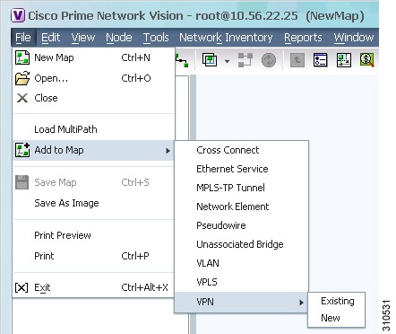
You can add the following types of elements to maps, as shown in Figure 4-1:
•
•
•
•
•
•
•
•
•
Figure 4-1 Available Elements to Add to Maps
If you choose to add a new VPN, the Create VPN dialog box is displayed. For information on creating a VPN, see Creating a VPN
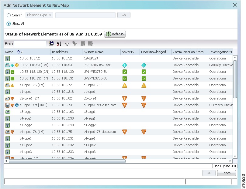
In all other instances, the Add element to map dialog box is displayed, as shown in Figure 4-2.
Figure 4-2 Add Element Dialog Box
Step 2
Note
•
a. In the Search field, choose a search category. Table 4-4 identifies the search categories available for each element type.
b. Enter a search string to narrow the display to a range of elements or to a specific element.
c. Click Go.
For example, if you add a network element, choose IP Address, and enter 254, the network elements with IP addresses containing the string 254 are displayed. If you choose Vendor and enter Cisco, only Cisco network elements are displayed.
•
The following conditions apply when working with large numbers of elements:
–
–
The Show All option is disabled because the retrieval time is expected to be
excessive.
Please define a search that is as specific as possible to minimize the data retrieval time.As recommended, use the Search option to specify search criteria and thereby limit the number of elements displayed.
The number of elements that can be displayed in the Add element dialog box is configured in the registry.
Note
The available elements are displayed in the Add element dialog box in table format. The dialog box also displays the date and time at which the list was generated. To update the list, click Refresh.
If a network element is not included in your scope, it is displayed with the locked device icon.
For information about sorting and filtering the table contents, see Working with Prime Network Tables.
Step 3
Step 4
If you select more than 25 business elements (such as VLANs or VPLS instances) to add, a message is displayed, stating that the action can take a while to complete and asking if you want to continue. Click OK to continue or Cancel to change your selection.
The elements are displayed in the navigation pane and content area. In addition, any associated tickets are displayed in the ticket pane.
The network element information is saved with the map in the Prime Network Vision database.
Resizing Map Elements
Prime Network Vision can display network element icons in four sizes. The size that is used when you add elements to a map depends on the number of elements in the map, the map layout, and the size of the content pane.
Icons at the top level of a map have a solid gray border when selected whereas element icons within an aggregation thumbnail have a dashed gray border when they are selected. However, if you double-click the thumbnail frame so that the aggregation fills the map pane and then select an element in the aggregation, the selected element displays a solid gray border.
You can resize element icons in the following ways:
Using Your Mouse
To resize a single icon in a map using your mouse:
Step 1
The icon displays a gray border to indicate that it is selected.
Step 2
Using the Resize Option
Note
To resize icons with the Resize option:
Step 1
Step 2
•
•
Step 3
•
•
Step 4
For more information about the information that is displayed in the element icons, see Information Available in Element Icons.
Using Zoom
Prime Network Vision enables you zoom in or out of maps so that you can use the viewing level that meets your needs. Zooming differs from resizing in that zooming does not change the size of the icon itself.
You can zoom in or out on a map by using either of the following methods:
•
–
–
•
–
–
- Position your mouse cursor in the map pane and use the mouse scroll wheel to zoom out.
- Click Fit in Window to view the entire map in the map pane.
Removing Elements from a Map
When you delete an element or aggregation from a map, it is removed from the map in the database, but the elements are still managed by Prime Network Vision.
Note
To remove a network element or aggregation from a map:
Step 1
Step 2
The element is removed from the map in the database, but is still managed by Prime Network Vision and can be added again.
Managing Maps
The following topics describe how to manage maps in Prime Network Vision:
•
•
•
Selecting Map Viewing Options
Table 4-5 describes the tools that you can use to view and manipulate maps in the Prime Network Vision map pane.
To select a tool, do one of the following:
•
•
Defining a Map Layout
Prime Network Vision enables you to select the way in which the network object topology is displayed with the following options: Circular, hierarchical, orthogonal, or symmetric.
Select the map layout by using either of the following methods:
•
•
When you choose a map layout, the elements align accordingly, using animation by default. Related characteristics, such as the speed of the animation and whether an expanded node causes sibling nodes to move aside, are also configured by settings in the registry.
Note
By default, Prime Network Vision uses the circular layout for maps. If you click Layout Map in the main toolbar, Prime Network Vision displays the map according to the option last selected.
Applying a Background Image
Prime Network Vision allows you to apply a background image to the map view. You can also choose the same background image or different images for other subordinate windows, such as detailed views of aggregations, VLANs, and VPNs.
The supported file formats are GIF, JPG/JPEG, and PNG.
Note
To apply a background image to a map:
Step 1
Step 2
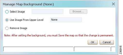
The Manage Map Background dialog box is displayed, as shown in Figure 4-3.
Figure 4-3 Manage Map Background Dialog Box
Step 3
Table 4-6 Manage Map Background Options
Select Image
Applies the selected image to the current map background:
1.
2.
3.
The name of the selected image is displayed in the Manage Map Background dialog box.
4.
Use Image From Upper Level
Indicates whether the selected subordinate map should use the same image as the parent map or a different image:
•
•
Remove Image
Removes the current image from the map background.
To remove an image from the current map, click Remove Image.
Step 4
Step 5
•
•
Using the Overview Window
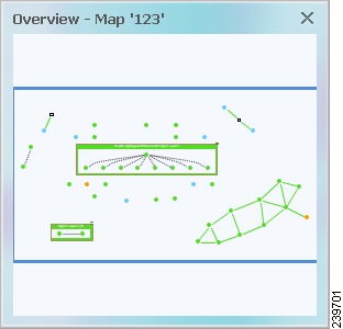
The Prime Network Vision Overview window enables you to display the entire network map or any part of the map that you require in the map pane. The Overview window also enables you to see all the changes and alarms taking place in the network.
To open the network Overview window do either of the following:
•
•
Figure 4-4 shows an example of the Overview window.
Figure 4-4 Overview Window
The Overview window can contain the following components:
•
•
•
•
•
Click the upper right corner to close the Overview window.
Renaming a Map
Prime Network Vision enables you to rename a map that is displayed in the Prime Network Vision window. The name change affects all users of the map and the new name is displayed in the Prime Network Vision window of all users.
To rename a map:
Step 1
•
•
Step 2
Step 3
Step 4
Step 5
Step 6
Saving Maps
Prime Network Vision provides three options for saving maps:
•
•
•
Saving a Map with Information
By default, Prime Network Vision saves basic map information whether or not you manually save the map. This default information includes element additions and removals, link additions and removals, aggregations, and disaggregations. However, you must use the Save Map option if you want to retain the following information in the database:
•
•
•
To save these changes, do one of the following:
•
•
Saving a Map as a New Map
You can save a copy of an entire map or parts of a map (such as specific elements and aggregations) while leaving the original map intact.
To save a map or part of a map as a new map:
Step 1
Step 2
Step 3
Step 4
Step 5
For information about opening the new map, see Opening a Map from the Open Map Dialog Box.
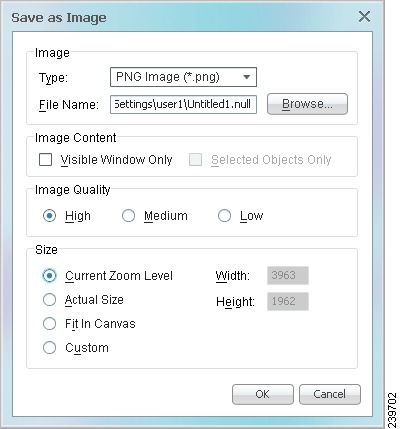
Saving a Map as an Image
To save a map as an image:
Step 1
Step 2
Step 3
Figure 4-5 Save as Image Dialog Box
Step 4
Previewing and Printing a Map
To print a map, choose File > Print. If you would like to preview a map before printing it, or define the print setup for a map, see the following topics:
•
•
Previewing a Map Before Printing It
Using Prime Network Vision, you can preview a map before printing it.
To preview a map:
Step 1
Step 2
The following buttons are displayed in the Print Preview window:
Step 3
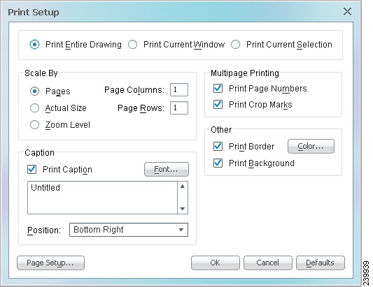
Defining the Print Setup for a Map
Prime Network Vision enables you to define the print setup of a map before it is printed.
To define the print setup:
Step 1
Step 2
Figure 4-6 Print Setup Dialog Box
Step 3
Step 4
The Print Preview dialog box is refreshed with the current settings.
Step 5
Deleting a Map from the Prime Network Vision Database
Prime Network Vision enables you to delete a map from all the views in the Prime Network Vision window.
If another client is using a map that you are deleting, Prime Network Vision displays a message to those clients advising them that the map is being closed and deleted from the database.
To delete a map from Prime Network Vision and the Prime Network Vision database:
Step 1
•
•
Step 2
a.
b.
c.
d.
e.
Finding Items in a Map
The following topics describe how to find network elements, services, links, or elements affected by a ticket in Prime Network Vision maps:
•
•
•
Finding a Network Element or Service
Prime Network Vision enables you to find an element or service (such as a VPN or VLAN) in the map by entering the element or service name, the device IP address, or any part of the name or IP address.
To find an element or service in a map:
Step 1
•
•
Step 2
Note
The Search all map levels check box enables you to search for an element, name, or IP address at all levels of the map. When disabled, this option searches for the element or service, but excludes aggregations from the search. This option is disabled by default.
Step 3
Step 4
Step 5
•
•
Finding and Selecting Links in Maps
Prime Network Vision enables you to find a specific link and select it in a map. If more than one edge device contains the same link in the same map or context, all related edge devices are selected in the map.
To find and select a link:
Step 1
The link is highlighted in the map pane.
Step 2
Step 3
For more information about links in Prime Network Vision, see Chapter 5 "Working with Links."
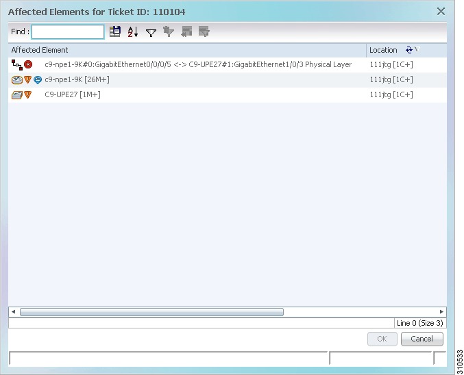
Finding Elements Affected by a Ticket
Prime Network Vision enables you to find the elements that might be affected by a ticket displayed in the ticket pane.
To find elements affected by a ticket:
Step 1
•
•
•
Figure 4-7 Affected Elements Window
Step 2
Step 3
Working with Aggregations
Prime Network Vision enables you to group network elements and display them as an aggregation. Aggregations can contain network elements, services, other aggregations, and so forth.
Note
For more information on working with aggregations, see the following topics:
•
•
•
Grouping Network Elements into Aggregations
To aggregate network elements:
Step 1
•
•
Step 2
•
•
•
Step 3
The aggregation icon changes color according to the alarm severity. For more information about severity colors, see Alarm Indicators.
Adding Elements to an Existing Aggregation
You can add elements to an existing aggregation at any time. When adding elements to an aggregation, keep in mind that certain restrictions exist. For example, you cannot add an EVC to a VLAN.
To add elements to an existing aggregation:
Step 1
Step 2
•
•
Step 3
Step 4
Step 5
•
•
•
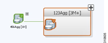
Viewing an Aggregation Thumbnail
You can view a thumbnail of a selected aggregation in the map pane, including all aggregated elements and any nested aggregations.
To display an aggregation thumbnail:
Step 1
•
•
The thumbnail is displayed in the map pane as shown in Figure 4-8.
Figure 4-8 Aggregation Thumbnail
When a thumbnail is opened, neighboring nodes are moved aside by default to allow room for the thumbnail to expand. Similarly, when a thumbnail is closed, the neighboring nodes usually return to their original locations. This behavior of the neighboring nodes when a thumbnail is opened and closed is configured in the registry, and can be disabled, if required.
Note
A dashed gray border around an icon indicates that the element resides within a thumbnail and not at the current map level.
Table 4-9 describes the options available when working with aggregation thumbnails.
Step 2
•
•
Renaming Aggregations
You can rename aggregations that are displayed in Prime Network Vision. The name change affects all users of the map, and the new name is displayed in the Prime Network Vision window of all users.
To rename an aggregation:
Step 1
Step 2
Step 3
Ungrouping Aggregations
Aggregations can be ungrouped. If the aggregation that you ungroup contains nested aggregations, the nested aggregations move up one level, and the original aggregation is removed.
If an element in the aggregation that you ungroup also exists at the parent level, the element is represented only once after the aggregation is ungrouped. As a result, no elements are represented twice at the same level.
To ungroup an aggregation:
Step 1
Step 2
•
•
•
If the aggregation contains elements that already exist at the parent level, a confirmation message is displayed, stating that any duplicate elements will be removed.
Step 3
The node is disaggregated. Any aggregations in the selected node move up one level, and the original aggregation is removed.
For more information about resizing aggregation icons, see Resizing Map Elements.
Working with Overlays
Prime Network Vision enables you to apply overlays to a map and thus isolate the parts of a network that are being used by a specific service.
The following topics discuss the overlay options in more detail:
Applying an Overlay
To apply an overlay:
Step 1
Step 2
With the exception of the None option, a dialog box is displayed that allows you to select the specific overlay to apply.
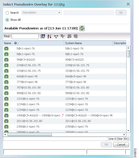
Figure 4-9 shows an example of the Select Pseudowire Overlay dialog box.
Figure 4-9 Select Overlay Dialog Box
Each overlay type allows you to search for specific overlays. Table 4-10 identifies the search fields available for each overlay type.
Step 3
•
a. Choose Search.
b. In the Search field, choose a search category.
c. Enter a search string to narrow the display to a range of overlays or to a specific overlay. Table 4-10 identifies the search categories available for each type of overlay.
d. Click Go.
Search strings are case-insensitive. If you choose Name and enter NET, the overlays that contain "net" in their names are displayed. If you choose System Name and enter System123, only the overlay with the system named System123 is displayed.
•
The available overlays that meet the specified search criteria are displayed in the Select Overlay dialog box in table format. The dialog box also displays the date and time at which the list was generated. To update the list, click Refresh.
Step 4
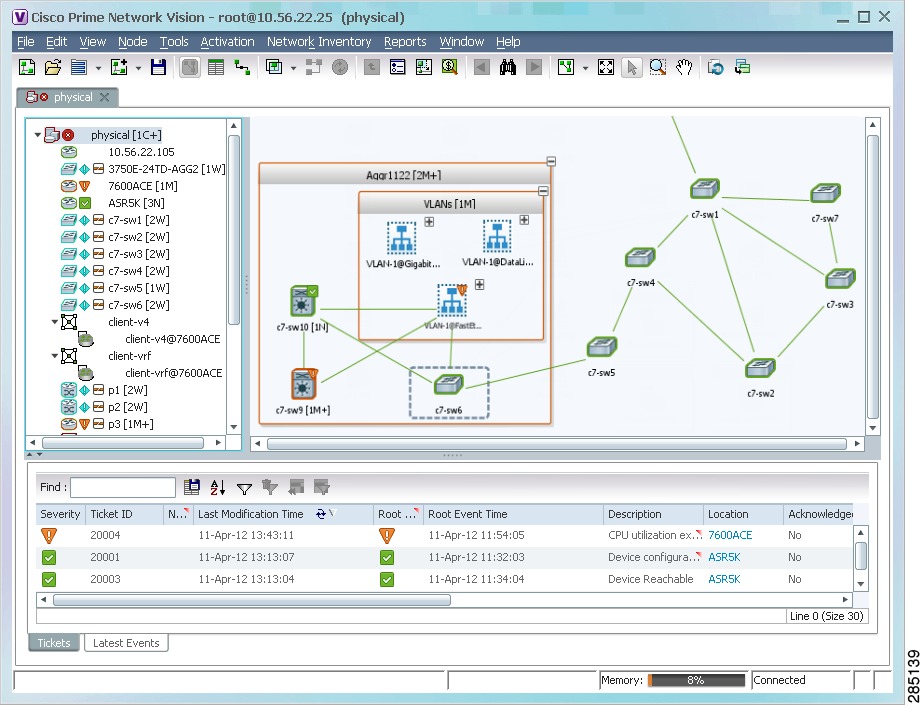
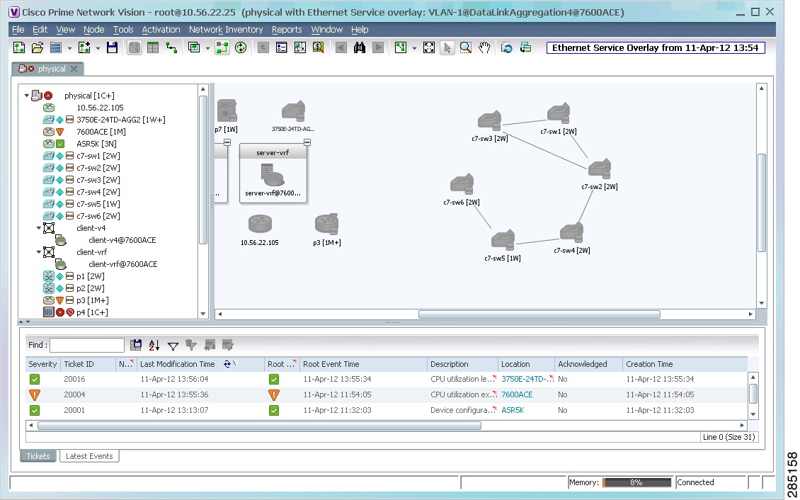
The elements and links that are used by the overlay are displayed in the map, and the overlay name and date are displayed in the toolbar, as shown in Figure 4-10.
Figure 4-10 Overlay Example
Note
Hiding or Viewing an Overlay
When an overlay is applied to a map, the Show Overlay/Hide Overlay button becomes active in the toolbar.
To hide and view the overlay, click Hide Overlay/Show Overlay in the toolbar. The button toggles depending on whether the overlay is currently displayed or hidden.
Removing an Overlay
To remove an overlay, choose Choose Overlay Type > None. The overlay is removed from the map.
Filtering Links in a Map
The links filter enables you to filter the links displayed in the map view and the links view.
You can quickly select the types of links to be filtered by selecting from a predefined set of link types in the list, or by manually configuring a customized set of link types.
To filter links, do either of the following:
•
•
The links filter applies to all aspects of Prime Network Vision: the map view, links view, ticket pane, severity calculation, and other items, such as memory consumption and thresholds. Prime Network Vision holds only the links that are relevant to the filter and synchronizes the links with the gateway according to that filter.
For more information about links in Prime Network Vision, see Chapter 5 "Working with Links."
Filtering Links During Map Creation
To filter links while creating a map:
Step 1
•
•
The Create Map dialog box is displayed. For more information, see Creating a New Map.
Step 2
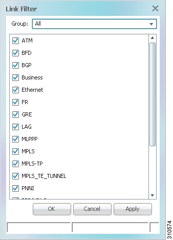
Figure 4-11 Link Filter Dialog Box
The Link Filter dialog box displays a list of all the types of links that you can filter in the map view and links view.
Note
Step 3
•
•
•
•
•
•
Note
Step 4
Step 5
Step 6
Step 7
Step 8
The links are displayed in the map view and links view according to your selections.
Filtering Links in an Existing Map
You can also create a map, add elements with all links enabled and visible in the map view and links view, and then filter (display or hide) the different types of links as required.
To filter links in an existing map:
Step 1
Step 2
Step 3
Step 4
The links are displayed in the map view and links view according to the defined filter, and the Link Filter Applied button is displayed in the to indicate that the links are filtered.
Opening the CPU Usage Graph
Prime Network Vision enables you to display memory and CPU usage information for a device or network element, including its history.
To open the CPU usage graph:
Step 1
The CPU Usage dialog box displays the following information:
•
•
•
•
Step 2
Step 3
Communicating with Devices Using Ping and Telnet
Prime Network Vision enables you to communicate with devices in the following ways:
Pinging a Device
Prime Network Vision enables you to ping a device to verify that the device is responding.
The ping is performed from the client to the device, and not from the Prime Network Vision unit hosting the VNE to the device.
To ping a device, right-click a device in the navigation tree or map, and choose Tools > Ping.
The results are displayed in a new window.
Telneting a Device
Prime Network Vision enables you to communicate with a device using the Telnet window.
The Telnet session is performed from the client to the device, and not from the Prime Network Vision unit hosting the VNE to the device.
Note
- For Windows 7 32-bit systems, enable the Windows Telnet Client to use the Prime Network Telnet option.
- For Windows 7 64-bit systems, a solution is available on the Cisco Developer Network at http://developer.cisco.com/web/prime-network/forums/-/message_boards/view_message/2780108/maximized?p_p_auth=jmRaG4QY.To telnet a device:
Step 1
Step 2