-
Cisco Prime Network User Guide, 3.9
-
Preface
-
Cisco Prime Network Client Overview
-
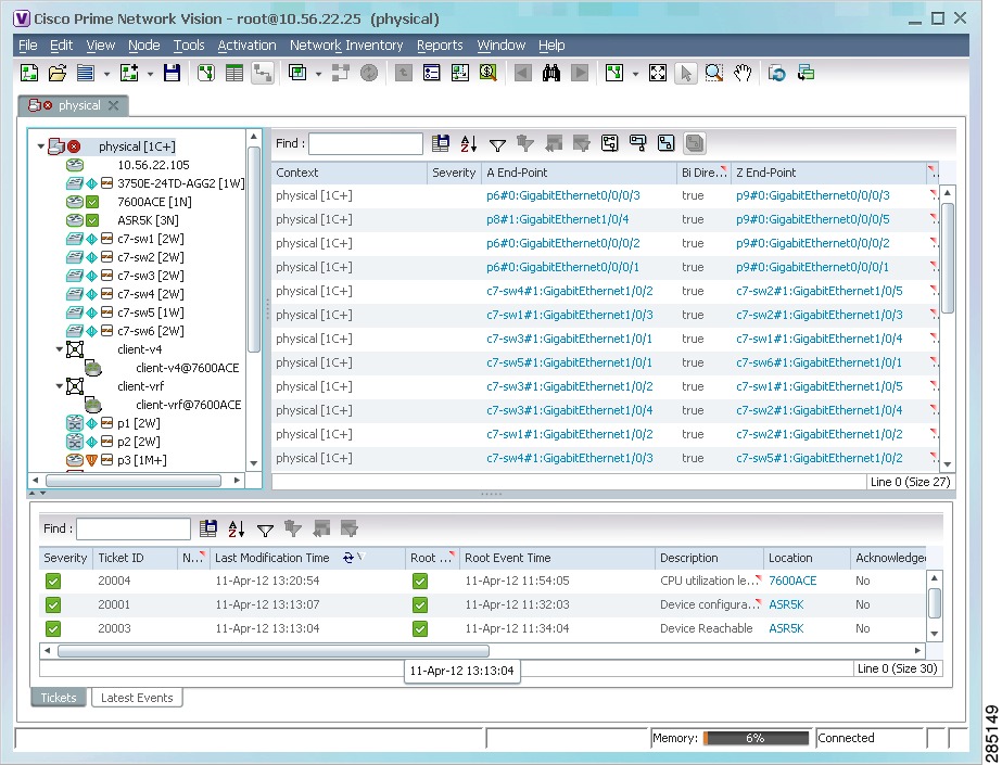
Working with the Cisco Prime Network Vision Client
-
Viewing Network Element Properties
-
Working with Prime Network Vision Maps
-
Working with Links
-
Working with Business Tags and Business Elements
-
Working with the Prime Network Events Client
-
Tracking Faults Using Prime Network Events
-
Working with Tickets in Cisco Prime Network Vision
-
Working with Reports
-
Using Cisco PathTracer to Diagnose Problems
-
Monitoring Carrier Ethernet Services
-
Monitoring Carrier Grade NAT Properties
-
Monitoring DWDM Properties
-
Viewing Ethernet Operations, Administration, and Maintenance Tool Properties
-
IPv6 and IPv6 VPN over MPLS
-
Monitoring MPLS Services
-
Monitoring MToP Services
-
Viewing SBC Properties
-
Viewing Mobile Technologies in Prime Network
-
Icon and Button Reference
-
Index
-
 Feedback
Table Of Contents
Working with the Cisco Prime Network Vision Client
User Roles Required to Work with Prime Network Vision
Launching Prime Network Vision
Launching Prime Network Vision from Prime Central
Launching Prime Network Vision as a Standalone Application
Prime Network Vision Inventory Tabs
Content Pane: Map, List, and Links Views
Prime Network Vision Status Indicators
Prime Network Vision Right-Click Menus
Changing a User Password in Prime Network Vision
Selecting Prime Network Vision Options
Working with Prime Network Tables
Using Keyboard Shortcuts in Tables
Working with the Cisco Prime Network Vision Client
The following topics describe the user access roles required to use Cisco Prime Network Vision (Prime Network Vision), the Prime Network Vision working environment, and how to access the Prime Network Vision tools and commands:
•
User Roles Required to Work with Prime Network Vision
•
•
•
•
•
•
•
User Roles Required to Work with Prime Network Vision
Table 2-1 identifies the GUI default permission or device scope security level that is required to work with Prime Network Vision. Prime Network Vision determines whether you are authorized to perform a task as follows:
•
•
For more information on user authorization, see the Cisco Prime Network 3.9 Administrator Guide.
By default, users with the Administrator role have access to all managed elements. To change the Administrator user scope, see the topic on device scopes in the Cisco Prime Network 3.9 Administrator Guide.
Table 2-1 Default Permission/Security Level Required for Prime Network Vision Functions
Start Prime Network Vision
X
X
X
X
X
Change a user password in Prime Network Vision
—1
—1
—1
—1
X1
Set Prime Network Vision options
X
X
X
X
X
Work with Prime Network Vision tables
X
X
X
X
X
1 Each user can change their own password, but only the Administrator role can change another user's password.
Launching Prime Network Vision
Prime Network provides two methods for launching Prime Network Vision:
•
•
Prime Network Vision is password protected to ensure security. Before you start working with Prime Network Vision, make sure you know your username and password. If you use the standalone application, you also need to know the Prime Network Vision gateway IP address or hostname.
Note
The following topics describe how to launch Prime Network Vision:
•
•
Launching Prime Network Vision from Prime Central
If Prime Central is available in your environment, you can launch Prime Network applications from the main Prime Central page.
To launch Prime Network Vision from Prime Central, choose Assure > Prime Network > Vision in the menu bar.
The Prime Network Vision application is opened in a separate window.
For more information about using Prime Network Vision with the Prime Central suite of products, see:
•
•
Launching Prime Network Vision as a Standalone Application
To launch Prime Network Vision as a standalone application:
Step 1
Note
The Cisco Prime Network Vision login dialog box is displayed.
Step 2
The Server field should already be populated with the hostname/IP address of the Prime Network gateway.
Step 3
If any client updates are available, Prime Network automatically installs them.
When you launch Prime Network Vision, messages are displayed if the server and client have different versions of the application that launches the client. For more information about these messages, see the Cisco Prime Network 3.9 Installation Guide.
The Prime Network Vision window appears empty when it is opened for the first time. You can create a new map or open a map that has been previously saved; see Chapter 4 "Working with Prime Network Vision Maps," for information on network maps. You can also open inventory tabs such as the Network Elements tab, which provides the available network element inventory. For more information on inventory tabs, see Prime Network Vision Inventory Tabs.
After logging into Prime Network Vision and launching the application, you can customize the Prime Network Vision settings. For example, you can:
•
•
•
•
For more information on customizing Prime Network Vision startup and display options, see Selecting Prime Network Vision Options.
Prime Network Vision Window
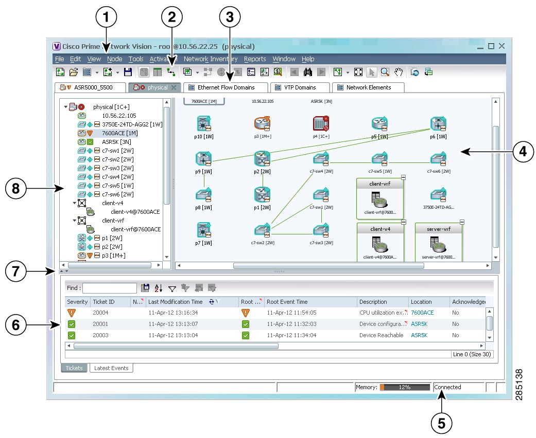
Figure 2-1 displays the Prime Network Vision window with an open map.
Figure 2-1 Prime Network Vision Window
Menu bar
Status bar
Toolbar
Ticket pane
Inventory and map tabs
Hide/display ticket pane
Content pane (showing the map view)
Navigation pane
The Prime Network Vision window can display either inventory tabs or maps. For more information, see the following topics:
•
The Prime Network Vision window enables you to:
•
•
•
•
•
•
•
Tip
The status bar at the bottom of the window provides information about the current connection status for the view. The status bar also displays information about the command that was sent while the application waits for an answer.
The memory utilization bar in the status bar displays the amount of memory used by the client. By default, if memory utilization exceeds 60%, it is colored yellow, and if it exceeds 80%, it is colored red.
Dragging the borders of the Prime Network Vision window adjusts the size of each pane. The navigation pane and content pane are correlated; this means that selecting an option in the navigation pane affects the information displayed in the content pane.
Prime Network Vision Inventory Tabs
The Prime Network Vision interface includes inventory tabs that enable you to access many Prime Network Vision features and functions without opening a map. For example, by opening the Network Elements inventory tab, you can:
•
–
–
–
–
•
•
Prime Network Vision includes the following inventory tabs:
•
–
–
•
•
Opening Inventory Tabs
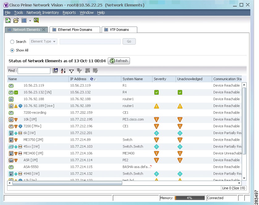
To open an inventory tab, either click the Network Elements icon in the toolbar or choose Network Elements in the menu bar, and choose the required option.
The selected inventory table is displayed as shown in Figure 2-2.
Figure 2-2 Prime Network Vision Inventory Tabs
The inventory tabs display the network inventory icon and name. If a tab is selected, it also displays an X for closing the tab. To close a tab that is not selected, place your cursor over that tab and click the X once it appears.
Working with Inventory Tabs
Table 2-2 describes the functions that are available for working with inventory tabs.
Table 2-2 Working with Inventory Tabs
Filter
Click Filter in the table toolbar and specify filter criteria.
For more information, see Filtering Table Contents.
Scroll
If the number of entries exceeds the current viewing area, use your mouse scroll wheel to move up and down through the table.
Search
This option is available only for the Network Elements tab.
To search for specific elements:
1.
2.
3.
4.
Sort
To sort:
•
•
For more information, see Sorting a Table.
Prime Network Vision Maps
Prime Network Vision enables you to visualize networks through network and service maps. These maps provide access to element physical and logical inventories, connectivity, and the current network and service states.
You can create as many maps as required to represent the network views you need. For example, maps can include specific network segments, customer networks, or the particular network elements and services that you require.
Each map is displayed in a tab that contains the following panes (as shown in Figure 2-1):
•
•
•
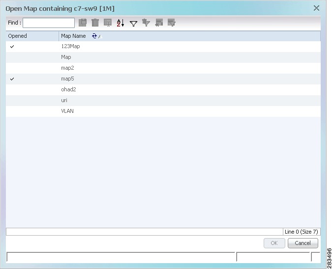
Opening Maps
You can open an existing map in any of the following ways:
•
•
•
•
The Open Map dialog box is displayed (see Figure 2-3).
Figure 2-3 Open Map Dialog Box
Depending on the method you use to open this dialog box, the Open Map dialog box lists either all maps or only those maps that contain the selected network element.
A check mark in the Opened column indicates that the map is already open.
Select the required maps and click OK.
Map tabs display the root node icon and name.
In addition, the icon color reflects the highest severity ticket that is not cleared in the map, and an alarm icon indicates the severity of the highest severity ticket that is not acknowledged. If a tab is selected, it also displays an X for closing the tab. To close a tab that is not selected, place your cursor over that tab and click the X once it appears.
For more information about maps, see Working with Prime Network Vision Maps.
Working with Multiple Tabs
Prime Network Vision enables you to open up to eight tabs at a time:
•
•
The following features can help you navigate multiple tabs more quickly:
•
–
–
•
•
•
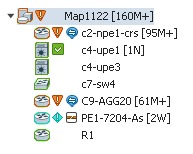
Navigation Pane
The navigation pane displays a tree-and-branch representation of the network elements and aggregations defined for the loaded map.
The highest level in the navigation tree displays root node icon with the map name. When the map name is changed, the Prime Network Vision window is updated, and the new map name is displayed at the top of the navigation tree and in the window title bar.
The lowest level of the navigation tree displays a single network element or service, such as a port, Ethernet flow point, or bridge.
The navigation pane can include up to two icons for each element. These icons can include alarm icons, communication or investigation state icons, and badges, as shown in Figure 2-4. Alarm icons are always displayed next to the element icon.
Figure 2-4 Navigation Pane with Icons
For information about the status of network objects, see Prime Network Vision Status Indicators.
Content Pane: Map, List, and Links Views
The content pane enables you to view and modify low-level information. It supports the following views:
•
•
•
When you switch between the map, list, and links views, the following are preserved:
•
•
•
–
–
–
Map View
Click Show Map View on the toolbar to display the map view in the Prime Network Vision window.
In the map view, Prime Network Vision displays:
•
•
–
–
•
•
•
•
•
•
•
•
–
–
•
The map view enables you to view network objects down to the device level. An example of the map view is displayed in Figure 2-1.
You can move network elements manually on the map by dragging the required icon. You can also click Layout Map in the toolbar or use your mouse to change the way the elements are displayed on the map. For more information about working with maps, see Chapter 4 "Working with Prime Network Vision Maps."
Element Icons
Prime Network Vision enables you to:
•
•
•
•
Table 2-3 provides examples of the four icons sizes and describes the information that is available with each.
For more information about using these features, see:
•
Prime Network Vision also provides additional features for working with aggregations. For more information, see Working with Aggregations.
The following tables identify some of the icons used to represent network elements and business elements in the Prime Network Vision window's navigation pane and content pane:
•
•
For a complete list of the icons and their descriptions, see "Icon and Button Reference."
Note
Links
Prime Network Vision maps contain graphical links that can represent multiple physical, topological, service, and business links.
The maximum number of graphical links that can be displayed is specified in the registry. If the number of graphical links exceeds the specified limit, a warning message with a Refresh button is displayed, and the map is surrounded by a red border. The presence of a red border around a map indicates that some links exist that are not displayed in the map.
Note
To reduce the number of graphical links in a map:
Step 1
•
a. Click Show Links View in the toolbar. The links view includes all links, even if the number of links exceeds the number of graphical links that can be displayed in a map.
b. Filter the links so that the map contains only the required links. For more information on filtering links, see Filtering Links in an Existing Map.
•
Only the links selected appear in the map and the Link Filter icon in the toolbar changes to indicate that a link filter is applied.
•
Step 2
Links in maps have tooltips that provide you with information regarding the link endpoints and the number of links represented by the selected link in the map. Click the link tooltip to view additional information about the link in a link quick view window. Click Properties in the link quick view window to open the link properties window. For more information about viewing link properties, see Viewing Link Properties in Prime Network Vision Maps.
Note
Alarm Indicators
Table 2-6 shows the colors that are used to display the severity (or propagated severity) of a network element in the navigation, content, and ticket panes.
Table 2-6 Severity Indicators
Red
Critical
Orange
Major
Yellow
Minor
Light Blue
Warning
Green
Cleared, Normal, or OK
Medium Blue
Information
Dark blue
Indeterminate
The same coloring conventions apply to the link severities displayed in the map view, links view, and link quick view.
Note
When you select an aggregation in the navigation tree, you can view the elements that belong to that aggregation in the map pane by either double-clicking its icon or clicking the plus sign in the upper right corner of its icon.
For more information about how the status of a network element is displayed in a map, see Prime Network Vision Status Indicators.
Right-Click Functions
Many functions can be performed by using the right-click menu in the map view, including launching external applications or tools. Some of these functions are also available in the navigation pane, links view, and ticket pane.
The specific options that are available in the right-click menu depend on whether you select a network element, click in the map background, select an aggregation, or select a ticket in the ticket pane. For details on the specific right-click options that are available for each scenario, see Prime Network Vision Right-Click Menus.
List View
Click Show List View in the toolbar to display the Prime Network Vision list view. The list view displays the tabs described in Table 2-7, depending on the items included in the current map and the item selected in the navigation tree.
Table 2-8 describes the network element properties displayed in the Network Elements tab. (Locked network elements display only managed element information and the locked element icon.) To ensure that you are viewing the latest information, either perform a new search or click the Refresh button.
Table 2-8 Network Element Information Displayed in List View
Name
Name of the network element managed by Cisco, as defined in Cisco Prime Network Administration. The Name property also displays a network element icon. The icon color reflects the highest network element alarm severity. In addition, the management state or an alarm icon is displayed.
IP Address
IP address used for managing the network element.
System Name
System name of the network element, as defined in the network element's MIB. If the network element is configured for Telnet access, the prompt is displayed.
Severity
Current operational health of the network element.
Unacknowledged
Severity of the most severe unacknowledged ticket.
Communication State
Ability of the VNE to reach the network element, according to the health of the element. For more information about communication states, see the Cisco Prime Network 3.9 Administrator Guide.
Investigation State
Level of network element discovery that has been performed or is being performed by the VNE. For more information about investigation states, see the Cisco Prime Network 3.9 Administrator Guide.
Vendor
Vendor name.
Product
Network element category, such as Router or Eth-Switch (Ethernet switch).
Device Series
Device series, such as Cisco 7600 Series Routers.
Element Type
Network element type including the manufacturer's name, such as Cisco 7200.
Software Version
Cisco IOS software version running on the network element.
Location
Location of the network element.
Up Since
Date and time the network element was last reset.
Tip
Table 2-9 identifies the buttons that are displayed in the list view toolbar.
Table 2-9 List View Toolbar
Find
Searches the table for the string you enter.
For more information, see Finding Text in a Table.
Export to CSV
Exports the information displayed in the table, or selected portions, to a CSV file.
For more information, see Exporting Tables to a File
Sort Table Values
Sorts the information displayed in the table by the criteria you specify.
For more information, see Sorting a Table.
Filter
Filters the information displayed in the table by the criteria you specify.
For more information, see Filtering Table Contents.
Clear Filter
Clears the existing filter.
Show All Rows
Displays all table rows that meet the current filtering criteria.
Show Only Selected Rows
Displays only the rows that you select.
For more information, see Viewing Selected Rows.
See Working with Prime Network Tables for more information about filtering, finding details about a network element in Prime Network Vision tables, and keyboard shortcuts available for accessing table functionality.
Table 2-10 describes some of the functions that are available from the right-click menu in the list view. You must select an item for the right-click menu to appear. Not all options are available for all selections.
Table 2-10 List View Right-Click Options
Inventory
View network element inventory
Poll Now
Poll the selected element
Attach / Detach / Edit Business Tag
Configure and view business tag information
Chapter 6 "Working with Business Tags and Business Elements"
Config Mgmnt
View the Configuration Management page in Prime Network Change and Configuration Management
Cisco Prime Network 3.9 Change and Configuration Management User and Administration Guide
Image Mgmnt
View the Image Management page in Prime Network Change and Configuration Management
Cisco Prime Network 3.9 Change and Configuration Management User and Administration Guide
Run Report
Generate reports
Show Only Selected Rows / Show All Rows
View selected rows or all rows
Tools
Ping or telnet a VNE, or check VNE CPU usage
Topology
Configure the topology
Properties
View network element properties
Commands
Launch any of the commands that are included with Prime Network Vision
Management
Access Command Builder and Soft Properties Management
VNE Tools
Poll a VNE, or start or stop a VNE
Tip
Links View
Click Show Links View in the toolbar to display the links view in the Prime Network Vision window.
Maps can contain many graphical links, each of which can represent multiple physical, topological, service, and business links. This can make it difficult for you to view the links you are interested in. In addition, if the number of graphical links exceeds the number that can be displayed in a map, not all links are displayed. By using the links view, you can view all links in the map, as well as search for a specific link and view the status of a link.
Note
Any links that are added or removed from the map are automatically added or removed from the links view, provided they have not been filtered out.
The links view is selection sensitive; that is, the links displayed in the links view depend on the context selected in the navigation pane or map. For example, if an aggregation is selected, the links in the selected aggregation are displayed in the links view.
Figure 2-5 shows a links view.
Figure 2-5 Links View
Note
Table 2-11 describes the information that is displayed in the links view.
Table 2-11 Information Displayed in the Links View
Context
Name of the map or aggregation containing the link.
This field can be empty for either of the following reasons:
•
•
Severity
Link alarm severity, represented by an icon. The icon and its color indicate the alarm severity and thereby the impact of the alarm on the network. For more information about severity, see Map View.
A End-Point
Element or site that is the source of the link as a hyperlink to the inventory of the element or site.
Bi Directional
Whether the link is bidirectional or unidirectional: true (bidirectional) or false (unidirectional). If the link is unidirectional (false), the traffic is from A to Z.
Z End-Point
Element or site that is the destination of the link as a hyperlink to the inventory of the element or site.
Link Type
Type of link, such as Physical Layer, LAG, MPLS TE Tunnel, pseudowire (PW) or VPN.
Note
The links view toolbar includes the tools described in Table 2-9 and the link filtering buttons described in Table 2-12.
For more information about filtering and sorting links in the links view, see Viewing Link Properties in the Links View.
For information about the right-click options available in the links view, see Links View Right-Click Menu.
Ticket Pane
The ticket pane shows the tickets that relate to the elements in the displayed map. It also contains the Latest Events tab that shows the latest incoming events for the elements in the map from the time the map was opened. See Chapter 9 "Working with Tickets in Cisco Prime Network Vision" for more information.
Prime Network Vision Status Indicators
The following topics describe the ways in which the status of an element is displayed in Prime Network Vision:
Severity
Severity indicates the operational health of the element. An element has only one severity value at any given time, and this value is displayed using a severity color. For more information about the colors used to display the severity (or propagated severity) of network elements and links, see Alarm Indicators.
Propagation
Severity is propagated upward in the network hierarchy, displaying the top-most severity of the network element's children and thereby ensuring that every single problem in the network is propagated and visible.
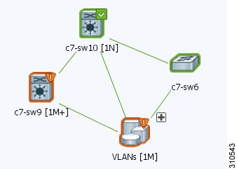
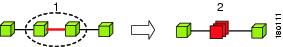
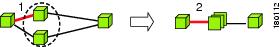
The same severity propagation rules that are used for network elements apply to links. A link is a child object of an aggregation only if it is fully contained in the aggregation; that is, the network elements on both sides of the link are part of the aggregation, as shown in Figure 2-6 and Figure 2-7.
Figure 2-6 Link Severity Example 1
Figure 2-6 shows critical link 1 between two network elements in an aggregation. This critical link affects the severity of aggregation 2. That is, the aggregation is critical because it contains a link with a critical severity. Link severity affects the context.
Figure 2-7 Link Severity Example 2
Figure 2-7 shows critical link 1 that forms part of a link aggregation. This affects the severity of link 2 because it contains a link with a critical severity.
New Ticket Propagation
A new ticket indicates a new local fault or accumulates and propagates the number of new faults in its children. New tickets are propagated upward, displaying the number of new tickets and the top-most severity.
When new tickets are accumulated, a label is displayed in the navigation pane and map, based on the following formula:
n s [+]
where:
For example:
•
•
An icon represents unacknowledged tickets, and the icon color is that of the most severe, unacknowledged ticket. For more information about severity colors and icons, see Alarm Indicators.
If all relevant tickets are acknowledged, no bell is displayed.
VNE Management State
The management state indicates the state or mode of the software component (a VNE) managing a network element and the communication with it. This enables you to determine the accuracy of the network information and the availability of VNEs to carry out network operations.
Management states are always local indications and are not propagated. A partial exception to this rule is the propagation of unreachable VNEs.
The management state indication applies only to VNE and its components. A VNE can have only one state at a time (for example, Unsupported or Connecting).
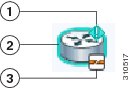
A managed VNE icon consists of a managed element icon and one or two overlay icons, or badges:
•
An element icon is colored green if either of the following is true:
–
–
For more information about network element icons, see Element Icons. For more information about severity colors, see Alarm Indicators.
•
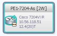
Figure 2-8 shows an example of an element with the following ticket and alarm severities:
–
–
Figure 2-8 Element with Ticket and Alarm Severity Indicators
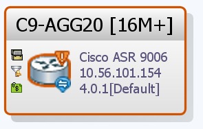
•
Figure 2-9 Element with Overlay Badges
Alarm badge with severity Warning.
Managed element icon with severity Warning.
VNE management state badge of Device Partially Reachable.
Table 2-13 and Table 2-14 describe network element communication and investigation states and shows the related badge for each state.
Table 2-13 VNE Communication States
Agent Not Loaded
The VNE is not responding to the gateway because it was stopped, or it was just created. This communication state is the equivalent of the Defined Not Started investigation state.
None
VNE/Agent Unreachable
The VNE is not responding to the gateway. This can happen if the unit or AVM is overutilized, the connection between the gateway and unit or AVM was lost, or the VNE is not responding in a timely fashion. (A VNE in this state does not mean the device is down; it might still be processing network traffic.)
Connecting
The VNE is starting and the initial connection has not yet been made to the device. This is a momentary state. Because the investigation state decorator (the hourglass) will already be displayed, a special GUI decorator is not required.
None
Device Partially Reachable
The VNE is not fully reachable because at least one protocol is not operational.
Note
Device Unreachable
The connection between the VNE and the device is down because all of the protocols are down (though the device might be sending traps or syslogs).
Note
Tracking Disabled
The reachability detection process is not enabled for any of the protocols used by the VNE. The VNE will not perform reachability tests nor will Cisco Prime Network generate reachability-related events. In some cases this is desirable; for example, tracking for Cloud VNEs should be disabled because Cloud VNEs represent unmanaged network segments.
Because this is a user-defined mode (rather than an error or transitional mode), Cisco Prime Network does not display a decorator for this state. To troubleshoot a VNE that is in this state, see the Cisco Prime Network 3.9 Administrator Guide.
None
Table 2-14 VNE Investigation States
Defined Not Started
A new VNE was created (and is starting); or an existing VNE was stopped. In this state, the VNE is managed and is validating support for the device type. (This investigation state is the equivalent of the Agent Not Loaded communication state.) A VNE remains in this state until it is started (or restarted).
None
Unsupported
The device type is either not supported by Prime Network or is misconfigured (it is using the wrong scheme, or is using reduced polling but the device does not support it).
To extend Cisco Prime Network functionality so that it recognizes unsupported devices, use the VNE Customization Builder. See the Cisco Prime Network 3.9 Customization User Guide.
Discovering
The VNE is building the model of the device (the device type was found and is supported by Cisco Prime Network). A VNE remains in this state until all device commands are successfully executed at least once, or until there is a discovery timeout.
Operational
The VNE has a stable model of the device. Modeling may not be fully complete, but there is enough information to monitor the device and make its data available to other applications, such as activation scripts. A VNE remains in this state unless it is stopped or moved to the maintenance state, or there are device errors.
None
Currently Unsynchronized
The VNE model is inconsistent with the device. This can be due to a variety of reasons; for a list of these reasons along with troubleshooting tips, see the topic on troubleshooting VNE investigation state issues in the Cisco Prime Network 3.9 Administrator Guide.
Maintenance
VNE polling was suspended because it was manually moved to this state (by right-clicking the VNE and choosing Actions > Maintenance). The VNE remains in this state until it is manually restarted. A VNE in the maintenance state has the following characteristics:
•
•
•
•
The VNE is moved to the Stopped state if: it is VNE is moved, the parent AVM is moved or restarted, the parent unit switches to a standby unit, or the gateway is restarted.
Partially Discovered
The VNE model is inconsistent with the device because a required device command failed, even after repeated retries. A common cause of this state is that the device contains an unsupported module.
To extend Cisco Prime Network functionality so that it recognizes unsupported modules, use the VNE Customization Builder. See the Cisco Prime Network 3.9 Customization User Guide.
Shutting Down
The VNE has been stopped or deleted by the user, and the VNE is terminating its connection to the device.
Stopped
The VNE process has terminated; it will immediately move to Defined Not Started.
None
More than one management state can occur at the same time. For example, a single overlay icon can be displayed, reflecting the device status based on the following priorities: Unsupported > Discovering > VNE/Agent Unreachable > Device Unreachable > Partially Discovered > Operational.
For more information about each of these states and how to troubleshoot any issues, see the Cisco Prime Network 3.9 Administrator Guide.
Tickets
Cisco Prime Network Vision displays an icon with a ticket to indicate the severity of the top-most alarm on the ticket. The icons are the same as those used with network elements (see Table 2-6) and are displayed in Cisco Prime Network Vision as follows:
Prime Network Vision Toolbar
The Prime Network Vision toolbar is context-sensitive and the options vary depending on your selection in the application.
Note
Table 2-15 identifies the toolbar buttons and describes the functions that are available in the Prime Network Vision toolbar.
Table 2-15 Prime Network Vision Toolbar
Open Network Inventory
Opens the Network Elements tab.
New Map
Creates a new map in the database.
Open Map
Opens a map saved in the database using the Open dialog box.
Add to Map
Adds an element to the map or to the subnetwork selected in the navigation pane and displayed in the content pane.
Save Map Appearance
Saves the current map (the background and the location of devices) to the database.
Show Map View
Displays the map view in the Prime Network Vision content pane (the button toggles when selected or deselected).
Show List View
Displays the list view in the Prime Network Vision content pane (the button toggles when selected or deselected).
Show Links View
Displays the links view in the Prime Network Vision content pane (the button toggles when selected or deselected).
Choose Overlay Type
Chooses and displays an overlay of a specific type on top of the elements displayed in the content pane in a map view.
Available overlay options are:
•
•
•
•
•
•
•
•
Show Overlay / Hide Overlay
Displays or hides a previously defined overlay on top of the elements displayed in the map view.
Note
Refresh Overlay
Refreshes the overlay that was last selected.
Go to Parent
Moves up one level in the navigation pane and content pane so you can view different information.
Link Filter
Opens the Link Filter dialog box, enabling you to display or hide different types of links in the map and links views.
If a link filter is applied to the map, the Link Filter Applied button is displayed instead.
Link Filter Applied
Indicates a link filter is currently applied to the map and opens the Link Filter dialog box so you can remove or modify the existing link filter.
If no link filter is applied to the map, the Link Filter button is displayed instead.
Overview
Opens a window displaying an overview of the network.
Find Business Tag
Opens the Find Business Tag dialog box, enabling you to find and delete a business tag according to name, key, or type.
Find Previous
Finds the previous instance of the search string entered in the Find in Map dialog box.
Find
Opens the Find in Map dialog box, enabling you to find an element in the map by its name or IP address.
Find Next
Finds the next instance of the search string entered in the Find in Map dialog box.
Layout Map
Defines the way in which the elements are arranged in the Prime Network Vision window: Circular, hierarchical, orthogonal, or symmetric.
Fit in Window
Fits all elements in the map in the content pane.
Normal Selection Mode
Activates the normal selection mode.
Zoom Selection Mode
Activates the zoom selection mode, which enables you to zoom in on a section of the map by clicking and dragging the required area.
Pan Mode
Activates the pan mode, which enables you to view different areas of the map by clicking and dragging the map.
Open Activation
Opens the Activation dialog box.
For more information, see the Cisco Prime Network 3.9 Customization User Guide.
Activation History
Opens the Activation History dialog box.
For more information, see the Cisco Prime Network 3.9 Customization User Guide.
Prime Network Vision Menu Bar
The following topics describe the options that are available in each Prime Network Vision menu:
Note
Note
File Menu
Table 2-16 describes the options that are available in the Prime Network Vision File menu. For more information, see Chapter 4 "Working with Prime Network Vision Maps."
Table 2-16 File Menu Options
New Map
Creates a new empty map in the database.
Open Map
Opens a map saved in the database using the Open dialog box.
Add to Map1
Opens the Add dialog box and enables you to add any of the following to the map or to the subnetwork selected in the navigation pane and displayed in the content pane:
•
•
•
•
•
•
•
•
•
Save Map1
Saves the appearance of the map (the background and the location of devices) to the database.
Save As Image1
Saves the active map as an image and automatically displays the Save as Image dialog box. Use this dialog box to save an image using a different file format or name.
Print Preview1
Displays how the map will look when it is printed.
Print1
Prints the active map as displayed in the Print Preview dialog box.
Load MultiPath
Loads a Cisco PathTracer multiple-path trace from a file that was previously saved in Cisco PathTracer.
Close
Closes the selected map or tab.
Exit
Exits the Prime Network Vision application and saves the content pane.
1 This option is available only when a map is displayed in the content pane.
Edit Menu
Table 2-17 identifies the options available in the Prime Network Vision Edit menu. For more information, see Chapter 4 "Working with Prime Network Vision Maps."
View Menu
Table 2-18 identifies the options available in the Prime Network Vision View menu. For more information, see Using the Overview Window.
Node Menu
Table 2-19 describes the Node menu options.
Note
Table 2-19 Node Menu Options
Inventory
Displays a dialog box that enables you to view the physical and logical inventory. For physical inventory, you can view all the components of the device, such as modules and ports. In addition, you can view the status of each component. For logical inventory, you can view all the profiles and virtual channels or routing tables of the device. For more information, see Chapter 3 "Viewing Network Element Properties."
Mark as A Side
Starts the process of creating a new static link. This option is enabled when a device, port, or unmanaged network is selected.
Mark as Z Side
Launches the Add Static Link dialog box, enabling you to create a static link between the two selected nodes. This option is enabled after a device, port, or unmanaged network is selected and after the Mark as A Side option is selected.
Note
Properties
Displays a dialog box enabling you to view the properties of the selected device, such as the severity, IP address, and communication state. For more information, see Chapter 3 "Viewing Network Element Properties."
Tools Menu
Table 2-20 describes the Tools menu options.
Table 2-20 Tools Menu Options
Change User Password
Enables you to change the password used when logging into the Prime Network client application suite. The change takes effect the next time you log into the application.
Note
Options
Enables you to customize several of Prime Network's options, such as whether or not to load the content upon startup. For more information, see Selecting Prime Network Vision Options.
Change and Config Mgmnt
Displays the Prime Network Change and Configuration Management dashboard.
For more information, see the Cisco Prime Network 3.9 Change and Configuration Management User and Administration Guide.
Command Jobs
Displays all Command Builder jobs that have been scheduled and their details.
For more information, see the Cisco Prime Network 3.9 Customization User Guide.
Activation Menu
See the Cisco Prime Network 3.9 Customization User Guide for more information about any of the options in this menu.
Table 2-21 describes the Activation menu options.
Network Inventory Menu
Table 2-22 describes the Network Inventory menu options.
Table 2-22 Network Inventory Menu Options
Network Elements
Displays a list of the available network elements in the Network Elements tab. For more information, see Prime Network Vision Inventory Tabs.
Ethernet Flow Domains
Displays a list of the current Ethernet flow domains in the Ethernet Flow Domains tab. For more information, see Viewing and Renaming Ethernet Flow Domains
VTP Domains
Displays a list of the current of the VLAN Trunk Protocol (VTP) domains in the VTP Domains tab. For more information, see Viewing VLAN Trunk Group Properties.
Reports Menu
Table 2-23 describes the Reports menu options.
For more information about Report Manager and reports, see Chapter 10 "Working with Reports."
Window Menu
The Prime Network Vision Window menu lists all maps open in the Prime Network Vision content pane, enabling you to move between the maps. The menu also lists any network element inventory tabs that are open.
Help Menu
Table 2-24 describes the Help menu options.
Prime Network Vision Right-Click Menus
If you right-click a specific area, link, network element, device, or alarm in a Prime Network Vision window, a context-sensitive right-click menu is displayed that contains options available for the selected item or items.
Right-click menus are also available in many of the inventory and property windows. For example, if you right-click an entry in a logical inventory table, you can view properties specific to that entry. The options that are available depend on the window or table currently displayed and the item selected.
The menus are context-sensitive and the options vary according to your selection in the application. For example, the right-click menus for network elements and aggregations are different.
Additional right-click options are displayed in the following situations:
•
•
•
The functionality that you can access in Prime Network Vision depends on your user role and the security level of the scopes that you can access. For more information, see User Roles Required for Working with Prime Network Vision Maps.
See the following topics for the default options available in Prime Network Vision right-click menus:
Map Right-Click Menu
The map right-click menu is displayed when you right-click anywhere on a map in the content pane and no elements are selected.
Table 2-25 describes the map right-click menu options.
Table 2-25 Map Right-Click Menu Options
Go to Parent
Moves up one level in the navigation pane and content pane to enable you to view different information.
Go to Root
Moves to the root level in the navigation pane and content pane to enable you to view different information.
Set Map Background
Displays a background image for the map in the content pane. For more information, see Applying a Background Image.
Element Right-Click Menu
The element right-click menu is displayed when you right-click an element in the navigation pane, the content pane, or in the Network Elements inventory tab.
Note
Table 2-26 describes the options available in the element right-click menu.
Table 2-26 Element Right-Click Menu Options
Add Associated VLAN
Opens the Add Associated VLAN dialog box so that you can add an associated VLAN to the selected VLAN. For more information, see Adding an Associated VLAN.
Aggregate
Groups the selected devices into an aggregation in the Prime Network Vision content pane, and enables you to define a name for the new aggregation. For more information, see Chapter 4 "Working with Prime Network Vision Maps."
Note
Attach / Detach / Edit Business Tag
Allows you to perform the following actions:
•
•
•
Note
For more information, see Chapter 6 "Working with Business Tags and Business Elements."
Commands
Enables you to launch any of the commands that are included with Prime Network Vision.
For more information on the available commands and how to implement them, see the "Using the Prime Network Basic Operation Commands" chapter in the Cisco Prime Network 3.9 Reference Guide.
Config Mgmnt
This option is available only if Prime Network Change and Configuration Management is installed.
Displays the Configuration Management page for the selected device in Prime Network Change and Configuration Management.
For more information, see the Cisco Prime Network 3.9 Change and Configuration Management User and Administration Guide.
Delete
Deletes the selected item from the map.
Disaggregate
Ungroups the devices in the selected aggregation in the navigation and map panes. For more information, see Chapter 4 "Working with Prime Network Vision Maps."
Note
Edit
Move the selected virtual router to the location you specify.
Filter Tickets
Displays only those tickets that have the selected VNE as the root cause.
This option is available only for VNEs that have not been deleted by Prime Network Administration.
Hide Connected Devices
Hides the devices for sites with one or more connected devices.
Image Mgmnt
This option is available only if Prime Network Change and Configuration Management is installed.
Displays the Image Management page for the selected device in Prime Network Change and Configuration Management.
For more information, see the Cisco Prime Network 3.9 Change and Configuration Management User and Administration Guide.
Inventory
Displays a window enabling you to view the physical and logical inventory. For physical inventory, you can view all the components of the device, such as the modules, ports, and its IP address or configured VLANs. In addition, you can view the status of each component. For logical inventory, you can view all the profiles and VC tables of the device. For more information, see Chapter 3 "Viewing Network Element Properties."
Launch external applications
Starts an external application or tool that has been configured for access via the right-click menu. For more information, see the Cisco Prime Network 3.9 Customization User Guide.
Management
Contains the following submenu options:
•
•
For more information about Command Builder and Soft Properties Manager, see the Cisco Prime Network 3.9 Customization User Guide.
Modify
Displays the Modify dialog box so that you can change the selected item's name, description, or icon.
Open Relevant Maps
Displays the Open Map dialog box so that you can view and open maps that contain the selected element.
PathTracer
Launches a path trace from the selected item.
Poll Now
Polls the selected element.
Properties
Displays the properties of the selected item, such as the IP address and system name. In addition, you can open the VNE Properties dialog box and manage VNE properties. For more information, see Chapter 3 "Viewing Network Element Properties."
Remove from Map
Removes the selected device and all its children from the map (navigation pane and content pane). The device that has been removed is still maintained in the network.
Rename
Renames the selected item.
Resize
Enables you to resize an object on the map by percentage or size.
Run Report
Enables you to run standard or user-defined events, inventory, and network service reports on demand.
Save as New Map
Creates a new map and places the selected aggregation as the root, while leaving the original map intact.
Script names
Launches available activation and configuration scripts. This can include the commands documented in Commands part of the Cisco Prime Network 3.9 Reference Guide, and those you create using Command Builder (can be launched against multiple network elements). For more information, see the Cisco Prime Network 3.9 Customization User Guide.
Show as Aggregation /
ThumbnailDisplays the selected aggregation as a single entity or as a collection of items.
The options toggle, depending on whether the aggregation is in a thumbnail or aggregated view.
Show CE Device
Displays devices for sites or LCPs with one or more hidden, connected devices.
Tools
The Tools option contains the following choices:
•
•
•
Note
- For Windows 7 32-bit systems, enable the Windows Telnet Client to use the Prime Network Telnet option.
- For Windows 7 64-bit systems, a solution is available on the Cisco Developer Network at http://developer.cisco.com/web/ana/forums/-/message_boards/message/2780108.Topology
The Topology option enables you to add:
•
•
•
When working with static links, the following submenu options enable you to define the A Side and Z Side of the link:
•
•
When working with VPNs in VPN Service View, the Add Tunnel submenu option allows you define and configure tunnels.
VNE Tools
Contains the following submenu options:
•
•
•
For more information, see Chapter 3 "Viewing Network Element Properties."
Aggregation Right-Click Menu
The aggregation right-click menu is displayed when you right-click an aggregation in a map.
Table 2-27 describes the aggregation right-click menu options.
Table 2-27 Aggregation Right-Click Menu Options
Aggregate
Groups the selected aggregations into an aggregation in the Prime Network Vision content pane, and enables you to define a name for the new aggregation. For more information, see Chapter 4 "Working with Prime Network Vision Maps."
Disaggregate
Ungroups the selected aggregation in the navigation pane and map in the Prime Network Vision window. All the aggregations in the selected node move up one level, and the original aggregation is removed. For more information, see Chapter 4 "Working with Prime Network Vision Maps."
Rename
Renames the selected aggregation.
Resize
Defines the size of selected aggregations in a map according to one of four sizes or according to a percentage of the current size.
Remove from Map
Removes the selected aggregation and all its children from the navigation pane and the map.
Save as New Map
Creates a new map and places the selected aggregation as the root, while leaving the original map intact.
Run Report
Enables you to run standard or user-defined events, inventory, and network service reports.
Show as Aggregation /
ThumbnailDisplays the aggregation as a single entity or as a collection of items.
The options toggle, depending on whether the aggregation is in a thumbnail or aggregated view.
Delete
Deletes the selected item.
This option is available when the item is marked with the reconciliation icon.
Link Right-Click Menu
The Link right-click menu is displayed when you right-click a link in the map view. For more information, see Chapter 5 "Working with Links."
Table 2-28 describes the link right-click menu options.
Table 2-28 Link Right-Click Menu Option
Properties
Displays the properties of the selected link.
List View Right-Click Menu
The list view right-click menu is displayed when you right-click an entry in the Network Elements tab in the list view table. For more information, see List View.
Table 2-29 describes the list view right-click menu options.
Table 2-29 List View Right-Click Menu Options - Network Elements Tab
Inventory
Displays a window enabling you to view the physical and logical inventory. For physical inventory, you can view all the components of the device, such as the modules, ports, and its IP address or configured VLANs. In addition, you can view the status of each component. For logical inventory, you can view all the profiles and VC tables of the device. For more information, see Chapter 3 "Viewing Network Element Properties."
Attach / Detach / Edit Business Tag
Allows you to perform the following actions:
•
•
•
Note
For more information, see Chapter 6 "Working with Business Tags and Business Elements."
Config Mgmnt
Displays the Configuration Management page for the selected device in Prime Network Change and Configuration Management.
For more information, see the Cisco Prime Network 3.9 Change and Configuration Management User and Administration Guide.
Image Mgmnt
Displays the Image Management page for the selected device in Prime Network Change and Configuration Management.
For more information, see the Cisco Prime Network 3.9 Change and Configuration Management User and Administration Guide.
Run Report
Enables you to run standard or user-defined events, inventory, and network service reports.
Show Only Selected Rows
Displays only the rows that you select.
For more information, see Viewing Selected Rows.
Show All Rows
Displays all table rows that meet the current filtering criteria.
Tools
Contains the following submenu options:
•
•
•
Note
- For Windows 7 32-bit systems, enable the Windows Telnet Client to use the Prime Network Telnet option.
- For Windows 7 64-bit systems, a solution is available on the Cisco Developer Network at http://developer.cisco.com/web/ana/forums/-/message_boards/message/2780108.Topology
Enables you to add:
•
•
•
When working with static links, the following submenu options enable you to define the A Side and Z Side of the link:
•
•
When working with VPNs in VPN Service View, the Add Tunnel submenu option allows you define and configure tunnels.
Launch external applications
Launches external applications or tools, such as an SSH client. See the Cisco Prime Network 3.9 Customization User Guide.
Properties
Displays the properties of the selected item, such as the IP address and system name. In addition, you can open the VNE Properties dialog box and manage VNE properties. For more information, see Chapter 3 "Viewing Network Element Properties."
Commands
Enables you to launch any of the commands that are included with Prime Network Vision. For a complete list of the available commands, see the Cisco Prime Network 3.9 Reference Guide.
Script names
Launches available activation and configuration scripts. This can include the commands documented in Commands part of the Cisco Prime Network 3.9 Reference Guide, and those you create using Command Builder (can be launched against multiple network elements). For more information, see the Cisco Prime Network 3.9 Customization User Guide.
Management
Contains the following submenu options:
•
•
For more information about Command Builder and Soft Properties Manager, see the Cisco Prime Network 3.9 Customization User Guide.
VNE Tools
Contains the following submenu options:
•
•
•
For more information, see Chapter 3 "Viewing Network Element Properties."
Links View Right-Click Menu
The links view right-click menu is displayed when you right-click a link in the links view table. For more information, see Chapter 5 "Working with Links."
Table 2-30 describes the links view right-click menu options.
Table 2-30 Links View Right-Click Menu Options
Attach Business Tag
Attaches a business tag to the selected link. For more information, see Chapter 6 "Working with Business Tags and Business Elements."
Detach/Edit Business Tag
Detaches or edits a business tag from the selected link. For more information, see Chapter 6 "Working with Business Tags and Business Elements."
The Detach and Edit options are available only when a business tag is attached to a link.
Select Link in Map
Highlights the selected link in the content pane.
Show Only Selected Rows
Displays only the rows that you select.
For more information, see Viewing Selected Rows.
Show All Rows
Displays all table rows that meet the current filtering criteria.
Properties
Displays the properties of the selected link.
Ticket Right-Click Menu
The Ticket right-click menu is displayed when you right-click a ticket in the ticket pane. The Ticket right-click menu enables you to view ticket properties and highlights the links or elements that are affected by a ticket. The Ticket menu also enables you to acknowledge, clear, and remove a ticket. For more information, see Chapter 9 "Working with Tickets in Cisco Prime Network Vision."
Table 2-31 describes the ticket right-click menu options.
Table 2-31 Ticket Right-Click Menu Options
Acknowledge
Acknowledges that the ticket is being handled; the ticket is displayed as true in the ticket pane. Acknowledging an alarm removes the alarm icon from the device icon. Multiple tickets can be acknowledged at the same time.
Clear
Approves the reported faulty ticket and clears the faulty networking entity from Prime Network. The ticket is displayed as Clear in the ticket pane.
Note
Remove
Removes the ticket and all its active subtickets from the ticket pane (this option is only available after the ticket has been cleared). The deleted tickets can be viewed using Cisco Prime Network Events. Multiple tickets can be removed at the same time.
Note
Clear and Remove
Approves the reported faulty ticket and clears the faulty networking entity from Prime Network. In addition, the ticket and all its active subtickets are removed from the ticket pane.
Find Affected Elements
Finds any elements affected by the selected ticket:
•
•
Show Only Selected Rows
Displays only the rows that you select.
For more information, see Viewing Selected Rows.
Show All Rows
Displays all table rows that meet the current filtering criteria.
Properties
Displays the Ticket Properties dialog box, enabling you to view ticket information, including impact analysis details of the affected parties and correlated alarms. See Viewing Ticket Properties.
Changing a User Password in Prime Network Vision
Prime Network enables you to provide authentication by Prime Network or an external Lightweight Directory Access Protocol (LDAP) server. The method used to change your password depends on whether authentication is provided by Prime Network or an LDAP server:
•
•
–
–
To change your password:
Step 1
Note
Step 2
•
•
•
Step 3
Selecting Prime Network Vision Options
Prime Network Vision enables you to select map, display, audio, event history size options.
To select Prime Network Vision options:
Step 1
Step 2
Step 3
Table 2-32 Prime Network Vision Display Options
Map Labels Font Size
In the drop-down list, choose the preferred font size for labels on maps. Font sizes are 26, 28, 30, 32, and 34, with a default of 30.
Show Severity Text
(e.g. [3M+]Check the check box to view severity labels in the navigation pane and maps, using the formula described in New Ticket Propagation.
Uncheck the check box to hide severity labels.
Show Acknowledged
Check the check box to view the number of both acknowledged and unacknowledged alarms in the network element display name.
Uncheck the check box to view only the number of unacknowledged alarms in the network element display name.
For example, assume that device NE1 has two alarms with the severity M. One of these two alarms is acknowledged, and the other is not. If you check the Show Acknowledged check box, the display name will be NE1 [2M]. If you uncheck the Show Acknowledged check box, the display name will be NE1 [1M].
Show Propagated
Check the check box to view propagated alarms on the specific entity.
Uncheck the check box to view only the alarms on the specific entity.
Display Name
Select the preferred setting for network element names:
•
•
•
Step 4
Table 2-33 Prime Network Vision Audio Options
Enable Audio Response for Alarm
Select the preferred setting for audio notifications:
•
•
If you uncheck the check box, continue with Step 6.
Critical
Specify the .wav file to use for critical alarms.
Major
Specify the .wav file to use for major alarms.
Minor
Specify the .wav file to use for minor alarms.
Loop Sound on Critical Alarm
Specify whether or not the critical alarm sound should sound continuously when a critical alarm is triggered:
•
•
Step 5
Step 6
Step 7
Working with Prime Network Tables
Prime Network uses tables to display different types of information. The following topics describe how to work with Prime Network tables so that you can view the information that you want and, optionally, save the information to a file:
To view all text in a table cell, you can do either of the following:
•
•
Table Toolbar Options
Table 2-34 describes the options available in table toolbars.
Table 2-34 Table Toolbar Options
Find
Searches the current table for the string you enter.
For more information, see Finding Text in a Table.
Export to CSV
Exports the information displayed in the table, or selected portions, to a CSV file.
For more information, see Exporting Tables to a File
Sort Table Values
Sorts the information displayed in the table by the criteria you specify.
For more information, see Sorting a Table.
Filter
Filters the information displayed in the table by the criteria you specify.
For more information, see Filtering Table Contents.
Clear Filter
Clears the existing filter.
Show All Rows
Displays all table rows that meet the current filtering criteria.
Show Only Selected Rows
Displays only the rows that you select.
For more information, see Viewing Selected Rows.
Using Keyboard Shortcuts in Tables
Table 2-35 lists the keyboard shortcuts that you can use when working with tables.
Finding Text in a Table
Prime Network Vision enables you to search for information about a specific entry in a table by entering search criteria, such as a partial IP address.
To find text in a table:
Step 1
Step 2
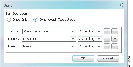
Sorting a Table
Prime Network Vision enables you to sort a table in the following ways:
•
•
•
A triangle next in the column heading indicates the sort order:
•
indicates the column is sorted in ascending order.
•
indicates the column is sorted in descending order.
To sort a table using the Sort Table Values option:
Step 1
Figure 2-10 Sort Dialog Box
Step 2
•
•
If you select this option, the
icon is displayed next to the selected column heading.
Step 3
a.
b.
Step 4
to add another sort criterion.
Step 5
•
.
•
.
Step 6
Filtering Table Contents
You can view only those items that are of interest to you by filtering a table's contents. This feature can be extremely helpful when working with tables that contain many entries.
Note
The following changes in the GUI indicate that a filter has been applied:
•
•
•
–
–
To define a filter:
Step 1
Figure 2-11 Table Filter Dialog Box
Step 2
•
•
Step 3
a.
b.
–
–
–
–
–
–
c.
–
–
Any entry that is not a regular expression is treated as a string.
Tip
Step 4
to add another criterion for this filter.
Step 5
.
Step 6
The table data is displayed using the defined filter.
Step 7
The table is refreshed and all entries are displayed.
The following tables have additional filtering capabilities:
•
•
Viewing Selected Rows
Prime Network enables you to select a line or a specific set of lines, and display them in the table. The lines that you do not select are hidden from view.
You can use this feature with the filtering mechanism to view the specific entries that you need. You can either select specific rows and then apply a filter, or you can filter the table's contents and then select specific rows to view.
If you apply a filter, the details of the filter are displayed below the table. For example, if you apply a filter that specifies all elements with names containing ME are to be displayed, the following appears in the table status line:
Filter: Name Contains METhe status bar below the table also displays the:
•
•
•
For example, if you select line four in a table with six rows, the following information is displayed:
Line 4 (1/6 Selected)If no rows are selected, the value for the line defaults to 0, such as:
Line 0 (Size 6)To view selected rows:
Step 1
Step 2
The table displays the selected rows, and the Show All Rows option becomes active.
Step 3
Exporting Tables to a File
Prime Network Vision enables you to export the currently displayed data from a table. You can either select specific rows to export, or clear all selections in the table to export the entire table. The data can then be imported and viewed at a later stage.
To export a table to a file:
Step 1
Step 2
•
•
Step 3
Step 4
Step 5
Step 6