Table Of Contents
Viewing Mobile Technologies in Prime Network
User Roles Required to View GGSN, GTPU, and APN Parameters
GGSN Overview
Viewing GGSN Properties
GTPU Overview
Viewing GTPU Properties
APN Overview
Viewing APN Properties
Viewing Additional Characteristics of an APN
Viewing Mobile Technologies in Prime Network
General Packet Radio Service (GPRS) and Universal Mobile Telecommunication System (UMTS) are evolutions of Global System for Mobile Communication (GSM) networks.
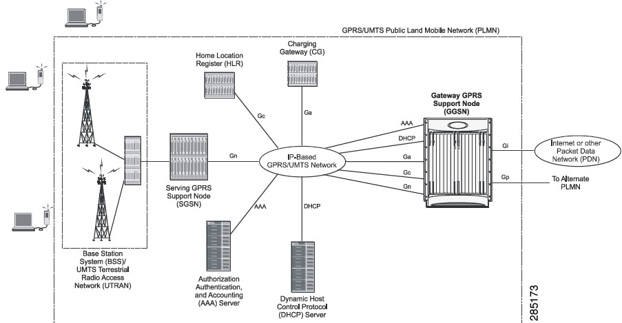
GPRS is a 2.5G mobile communications technology that enables mobile wireless service providers to offer their mobile subscribers packet-based data services over GSM networks. UMTS is a 3G mobile communications technology that provides wideband code division multiple access (CDMA) radio technology. Figure 20-1 shows a basic GPRS/UMTS network topology.
Figure 20-1 Basic GPRS/UMTS Network Topology
The GPRS/UMTS packet core comprises two major network elements:
•
Gateway GPRS support node (GGSN)—A gateway that provides mobile cell phone users access to a Packet Data Network (PDN) or specified private Internet Protocol (IP) networks.
•
Serving GPRS support node (SGSN)—Connects the radio access network (RAN) to the GPRS/UMTS core and tunnels user sessions to the GGSN. The SGSN sends data to and receives data from mobile stations, and maintains information about the location of a mobile station (MS). The SGSN communicates directly with the MS and the GGSN.
PDNs are associated with Access Point Names (APNs) configured on the system. Each APN consists of a set of parameters that dictate how subscriber authentication and IP address assignement is to be handled for that APN.
You can configure GGSN, associated GPRS Tunneling Protocol User Plane (GTPU), and APN with the required parameters using command-line interface (CLI). Prime Network Vision allows you to view the properties of GGSN, GTPU, and APN configured on the system.
From Prime Network 3.9, the mobile technologies are supported on Cisco Aggregation Service Router (ASR) 5000 series mobile gateways.
This chapter contains the following sections:
•
User Roles Required to View GGSN, GTPU, and APN Parameters
•
GGSN Overview
•
Viewing GGSN Properties
•
GTPU Overview
•
Viewing GTPU Properties
•
APN Overview
•
Viewing APN Properties
User Roles Required to View GGSN, GTPU, and APN Parameters
This topic identifies the GUI default permission or scope security level that is required to view the GGSN and APN properties in Prime Network Vision. Prime Network determines whether you are authorized to perform a task as follows:
•
For GUI-based tasks (tasks that do not affect elements), authorization is based on the default permission that is assigned to your user account.
•
For element-based tasks (tasks that do affect elements), authorization is based on the default permission that is assigned to your account. That is, whether the element is in one of your assigned scopes and whether you meet the minimum security level for that scope.
For more information on user authorization, see the Cisco Prime Network 3.9 Administrator Guide.
The following tables identify the tasks that you can perform:
•
Table 20-1 identifies the tasks that you can perform if a selected element is not in one of your assigned scopes.
•
Table 20-2 identifies the tasks that you can perform if a selected element is in one of your assigned scopes.
By default, users with the Administrator role have access to all managed elements. To change the Administrator user scope, see the topic on device scopes in the Cisco Prime Network 3.9 Administrator Guide.
Table 20-1 Default Permission/Security Level Required for Viewing GGSN, GTPU, and APN Properties - Element Not in User's Scope
Task
|
Viewer
|
Operator
|
OperatorPlus
|
Configurator
|
Administrator
|
GGSN
|
Viewing GGSN properties
|
—
|
—
|
—
|
—
|
X
|
GTPU
|
Viewing GTPU properties
|
—
|
—
|
—
|
—
|
X
|
APN
|
Viewing APN properties
|
—
|
—
|
—
|
—
|
X
|
Viewing additional APN characterisitcs
|
—
|
—
|
—
|
—
|
X
|
Table 20-2 Default Permission/Security Level Required for Viewing GGSN, GTPU, and APN Properties - Element in User's Scope
Task
|
Viewer
|
Operator
|
OperatorPlus
|
Configurator
|
Administrator
|
GGSN
|
Viewing GGSN properties
|
X
|
X
|
X
|
X
|
X
|
GTPU
|
Viewing GTPU properties
|
X
|
X
|
X
|
X
|
X
|
APN
|
Viewing APN properties
|
X
|
X
|
X
|
X
|
X
|
Viewing additional APN characterisitcs
|
X
|
X
|
X
|
X
|
X
|
GGSN Overview
The GGSN works in conjunction with SGSNs within the network to perform the following functions:
•
Establish and maintain subscriber Internet Protocol (IP) or Point-to-Point Protocol (PPP) type Packet Data Protocol (PDP) contexts originated by either the mobile or the network.
•
Provide charging detail records (CDRs) to the charging gateway (CG, also known as the Charging Gateway Function (CGF)).
•
Route data traffic between the subscriber's Mobile Station (MS) and a PDN such as the Internet or an intranet.
In addition, to providing basic GGSN functionality as described above, the system can be configured to support Mobile IP and/or Proxy Mobile IP data applications in order to provide mobility for subscriber IP PDP contexts. When supporting these services, the system can be configured to function as a GGSN and Foreign Agent (FA), a stand-alone Home Agent (HA), or a GGSN, FA, and HA simultaneously within the carrier's network.
Viewing GGSN Properties
Prime Network Vision displays the GGSNs in a GGSN container under the Mobile node in the logical inventory. The icon used for representing GGSNs in the logical inventory is explained in Logical Inventory Icons.
To view GGSN properties:
Step 1
Right-click the required device in Prime Network Vision and choose Inventory.
Step 2
In the logical inventory window, choose Logical Inventory > Context > Mobile > GGSN Container.
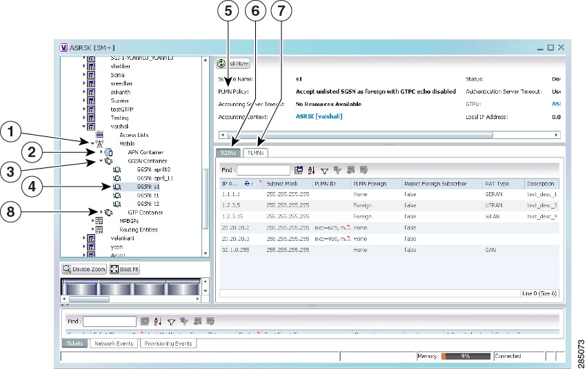
Prime Network Vision displays the list of GGSNs configured under the container as shown in Figure 20-2. You can view the individual GGSN details from the table on the right pane or by choosing Logical Inventory > Context > Mobile > GGSN Container > GGSN.
Figure 20-2 GGSN Properties in Logical Inventory
1
|
Mobile node
|
5
|
GGSN properties
|
2
|
APN container
|
6
|
Associated SGSNs
|
3
|
GGSN container
|
7
|
Associated PLMNs
|
4
|
GGSN
|
8
|
GTP container
|
Table 20-3 describes the details available for each GGSN.
Table 20-3 GGSN Properties in Logical Inventory
Field
|
Description
|
Service Name
|
The name of the GGSN service.
|
Status
|
The status of the GGSN service. Value could be Unknown, Running, or Down.
|
PLMN Policy
|
The PLMN policy for handling communications from SGSNs that are not configured to communicate with.
|
Newcall Policy
|
Specifies whether to accept or reject a new incoming call.
|
Authentication Server Timeout
|
The code used by the GGSN as a response message if communication with an authentication server times out. Value could be System Failure or User Authentication Failed.
|
Accounting Server Timeout
|
The code used by the GGSN as a response message if communication with an accounting server times out. Value could be System Failure or No Resouces.
|
GTPU
|
The GTPU that is associated with the GGSN and manages the GTP messages between GGSN and a radio access network equipment (RNC).
|
Accounting Context
|
The context that processes accounting for PDP contexts handled by the GGSN service.
|
Local IP Address
|
The local IP address bounded with the GGSN service.
|
GTPU
|
Service Name
|
The name of the GTPU service.
|
State
|
The status of the GTPU service. Status could be Unknown, Running, or Down.
|
Max Retransmissions
|
The maximum limit for GTPU echo retransmissions. Default value is 4.
|
Retransmission Timeout
|
The timeout in seconds for GTPU echo retransmissions. Default value is 5 Secs.
|
Echo Interval
|
The rate at which the GTPU echo packets are sent.
|
IPSEC Tunnel Idle Timeout
|
The IPSec tunnel idle timeout after which IPSec tunnel deletion is triggered. Default value is 60 Secs.
|
Allow Error Indication
|
Specifies whether error indication is dropped or sent without IPSec tunnel. Default value is Disabled.
|
Include UDP Port Ext Hdr
|
Specifies whether to include an extension header in the GTPU packet for error indication messages. Default value is False.
|
IP Address
|
The list of IP addresses configured on the GTPU. The IP addresses are available only when configured for the GTPU.
|
If the GGSN is associated with SGSNs and Public Land Mobile Networks (PLMNs), you can view the details from the respective tabs for that GGSN as shown in Figure 20-2.
Table 20-4 describes the SGSN and PLMN information associated with the GGSN.
Table 20-4 SGSN and PLMN information for a GGSN
Field
|
Description
|
SGSNs
|
IP Address
|
The IP address of the SGSN.
|
Subnet Mask
|
The subnet mask of the SGSN.
|
PLMN ID
|
The PLMN ID associated with the SGSN.
|
MCC
|
The mobile country code (MCC) portion of the PLMN.
|
MNC
|
The mobile network code (MNC) portion of the PLMN.
|
PLMN Foreign
|
Indicates whether the SGSN belongs to a home or foreign PLMN. This field is available only if MCC and MNC are not available.
|
Reject Foreign Subscriber
|
Specifies whether to accept or reject foreign subscriber. Value could be True or False.
|
RAT Type
|
The type of radio access technology (RAT) that is used for communication.
|
Description
|
The description of the SGSN entry in the GGSN service.
|
PLMNs
|
PLMN ID
|
The ID of the PLMN associated with the GGSN.
|
Primary
|
Indicates whether the PLMN ID is the primary PLMN ID for the GGSN. Value could be True or False. When multiple PLMN IDs are configured, the one configured as primary is used for the Authentication, Authorization, and Accounting (AAA) attribute.
|
GTPU Overview
The GGSN communicates with SGSNs on a Public Land Mobile Network (PLMN) using the GPRS Tunneling Protocol (GTP). The signaling or control aspect of this protocol is referred to as the GTP Control Plane (GTPC) while the encapsulated user data traffic is referred to as the GTP User Plane (GTPU). GTPU is used for transferring user data in separated tunnels for each PDP context.
You can configure various parameters for a GTPU using the command-line interface. You can view the configured parameters for a GTPU in the logical inventory.
Viewing GTPU Properties
Prime Network Vision displays the GTPUs in a GTP container under the Mobile node in the logical inventory. The icon used for representing GTPUs in the logical inventory is explained in Logical Inventory Icons.
To view GTPU properties:
Step 1
Right-click the required device in Prime Network Vision and choose Inventory.
Step 2
In the logical inventory window, choose Logical Inventory > Context > Mobile > GTP Container.
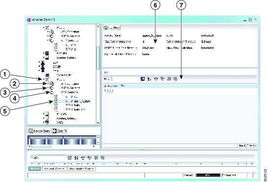
Prime Network Vision displays the list of GTPUs configured under the container as shown in Figure 20-3. You can view the individual GTPU details from the table on the right pane or by choosing Logical Inventory >Context > Mobile > GTP Container > GTPU.
Figure 20-3 GTPU Properties in Logical Inventory
1
|
Mobile node
|
5
|
GTPU
|
2
|
APN container
|
6
|
GTPU properties
|
3
|
GGSN container
|
7
|
IP addresses configured
|
4
|
GTP container
|
|
|
Table 20-5 describes the details available for each GTPU.
Table 20-5 GTPU Properties in Logical Inventory
Field
|
Description
|
Service Name
|
The name of the GTPU service.
|
State
|
The status of the GTPU service. Status could be Unknown, Running, or Down.
|
Max Retransmissions
|
The maximum limit for GTPU echo retransmissions. Default value is 4.
|
Retransmission Timeout
|
The timeout in seconds for GTPU echo retransmissions. Default value is 5 Secs.
|
Echo Interval
|
The rate at which the GTPU echo packets are sent.
|
IPSEC Tunnel Idle Timeout
|
The IPSec tunnel idle timeout after which IPSec tunnel deletion is triggered. Default value is 60 Secs.
|
Allow Error Indication
|
Specifies whether error indication is dropped or sent without IPSec tunnel. Default value is Disabled.
|
Include UDP Port Ext Hdr
|
Specifies whether to include an extension header in the GTPU packet for error indication messages. Default value is False.
|
IP Address
|
The list of IP addresses configured on the GTPU. The IP addresses are available only when configured for the GTPU.
|
APN Overview
APN is the access point name that is configured in the GGSN configurations. The GGSN's APN support offers the following benefits:
•
Extensive parameter configuration flexibility for the APN.
•
Extensive QoS support.
•
Virtual APNs to allow differentiated services within a single APN. The APN that is supplied by the SGSN is evaluated by the GGSN in conjunction with multiple configurable parameters. Then the GGSN selects an APN configuration based on the supplied APN and those configurable parameters.
Up to 1024 APNs can be configured in the GGSN. An APN may be configured for any type of PDP context, i.e., PPP, IPv4, IPv6 or both IPv4 and IPv6.
Many parameters can be configured independently for each APN by using the CLI. They are categorized as given below:
•
Accounting—RADIUS, GTPP, or none. Server group to use. Charging characteristics. Interface with mediation servers.
•
Authentication—Protocol, such as, Challenge Handshake Authentication Protocol (CHAP), Password Authentication Protocol (PAP), or none. Default username/password. Server group to use. Limit for number of PDP contexts.
•
Enhanced Charging—Name of rulebase to use, which holds the enhanced charging configuration (e.g., eG-CDR variations, charging rules, prepaid/postpaid options, etc.).
•
IP: Method for IP address allocation (e.g., local allocation by GGSN, Mobile IP, Dynamic Host Control Protocol (DHCP), DHCP relay, etc.). IP address ranges, with or without overlapping ranges across APNs.
•
Tunneling: PPP may be tunneled with L2TP. IPv4 may be tunneled with GRE, IP-in-IP or L2TP. Load-balancing across multiple tunnels. IPv6 is tunneled in IPv4. Additional tunneling techniques, such as, IPsec and VLAN tagging may be selected by the APN, but are configured in the GGSN independently from the APN.
•
QoS: IPv4 header ToS handling. Traffic rate limits for different 3GPP traffic classes. Mapping of R98 QoS attributes to work around particular handset defections. Dynamic QoS renegotiation (described elsewhere).
You can view the configured parameters for an APN in the logical inventory. After an APN is determined by the GGSN, the subscriber may be authenticated/authorized with an AAA server. The GGSN allows the AAA server to return VSAs (Vendor Specific Attributes) that override any or all of the APN configuration. This allows different subscriber tier profiles to be configured in the AAA server, and passed to the GGSN during subscriber authentication/authorization.
Viewing APN Properties
Prime Network Vision displays the APNs in an APN container under the Mobile node in the logical inventory. You can also view additional characteristics configured on the APN as explained in Viewing Additional Characteristics of an APN. The icon used for representing APNs in the logical inventory is explained in Logical Inventory Icons.
To view APN properties:
Step 1
Right-click the required device in Prime Network Vision and choose Inventory.
Step 2
In the logical inventory window, choose Logical Inventory >Context > Mobile > APN Container >APN.
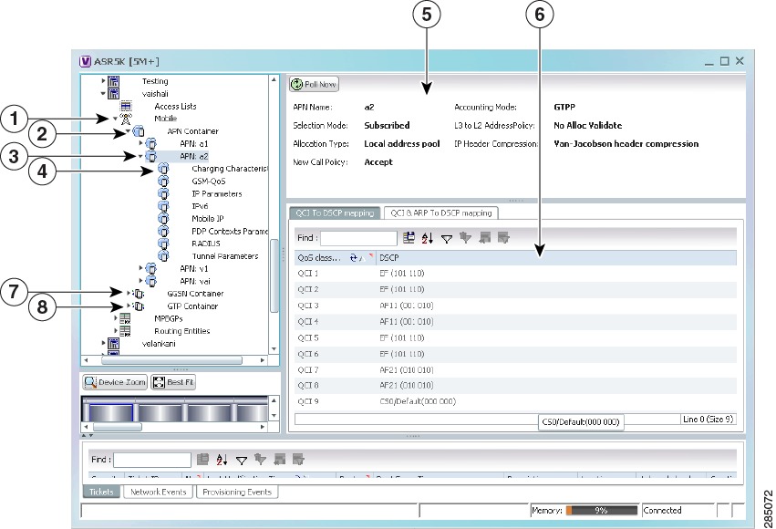
The APN details are displayed as shown in Figure 20-4.
Figure 20-4 APN Properties in Logical Inventory
1
|
Mobile node
|
5
|
APN properties
|
2
|
APN container
|
6
|
APN additional properties
|
3
|
APN
|
7
|
GGSN container
|
4
|
Configured APN characteristics
|
8
|
GTP container
|
Table 20-6 describes the information that is available for the APN. The information that is displayed depends on the configuration of the APN.
Table 20-6 APN Properties in Logical Inventory
Field
|
Description
|
APN Name
|
The APN name.
|
Accounting Mode
|
The accounting protocol in use in the APN. Values are GTPP (GPRS Tunneling Protocol Prime), RADIUS (Remote Authentication Dial In User Service), or None.
|
Selection Mode
|
The selection mode in use in the APN. Selection mode indicates the origin of the requested APN and whether or not the Home Location Register (HLR) has verified the user subscription.
|
L3 to L2 Address Policy
|
The layer 2 to layer 3 IP address allocation or validation policy.
|
Allocation Type
|
The method by which the APN obtains IP addresses for PDP contexts.
|
IP Header Compression
|
IP packet header compression parameters for the APN.
|
New Call Policy
|
Specifies whether to accept or reject a new incoming call in case of duplicate session calls with a request for same IP address.
|
Step 3
To view additional details configured for the APN, use the following tabs:
•
Virtual APNs—A virtual APN is a non-physical entity that represents an access point that does not itself provide direct access to a real target network. A virtual APN can be used to consolidate access to multiple, physical target networks through a single access point.
•
QCI to DSCP Mapping—Shows the mapping between QoS Class Indices (QCI) to Differentiated Services Code Point (DSCP).
•
QCI & ARP DSCP Mapping—Shows the mapping between QCI and Allocation/Retention Priority (ARP) to DSCP.
Field
|
Description
|
Virtual APNs
|
Preference
|
Specifies the order in which the referenced APNs are compared by the system. Can be configured to any integer value from 1 (highest priority) to 1000 (lowest priority).
|
APN
|
Specifies the name of an alternative APN configured on the system that is to be used for PDP contexts with matching properties. Value can be from 1 to 62, alpha and/or numeric characters, and is not case-sensitive. It may also contain dots ( . ) and/or dashes (- ).
|
Rule Definition
|
The virtual APN rule definition can be one of the following:
• access-gw-address—Specifies the access gateway (SGSN/SGW/Others) address for the virtual APN. The IP address can be an IPv4 or IPv6 address in decimal notation. IPv6 also supports :: notation for the IP address.
• bearer-access-service—Specifies the bearer access service name for the virtual APN.
• service name—Specifies the service name. Service name is unique across all the contexts. Value is a string of size 1 to 63.
• cc-profile—Specifies the APN for charging characteristics (CC) profile index. Value is an integer from 1 to 15.
• Domain name—Specifies the subscriber's domain name (realm). Domain name can be from 1 to 79 alpha and/or numeric characters.
• MCC—Specifies the MCC portion of the PLMN identifier. Value is an integer between 100 to 999.
• MCN—Specifies the MNC portion of the PLMN identifier. Value is an integer between 00 to 999.
• msisdn-range—Specifies the APN for this MSISDN range. The starting and ending values of the range is a string of size 2 to 15 with values between 00 and 999999999999999.
• Rat-Typ—Specifies the rat-type option, which could be gan, geran, hspa, utran, or wlan.
• Roaming mode—Specifies the roaming mode, which could be Home, Visiting, or Roaming.
|
QCI to DSCP Mapping
|
QoS class index
|
Denotes a set of transport characteristics used to differentiate various packet flows.
|
DSCP
|
Denotes a mechanism for classifying and managing network traffic and providing QoS.
|
QCI & ARP DSCP Mapping
|
QoS class index
|
Denotes a set of transport characteristics used to differentiate various packet flows.
|
Allocation retention priority
|
Indicates the priority of allocation and retention of the service data flow. This parameter allows prioritizing allocation of resources during bearer establishment and modification. During network traffic congestions, a lower ARP flow is dropped to free up the capacity.
|
DSCP
|
Denotes a mechanism for classifying and managing network traffic and providing QoS.
|
Viewing Additional Characteristics of an APN
To view additional characteristics of an APN:
Step 1
Right-click the required device in Prime Network Vision and choose Inventory.
Step 2
In the logical inventory window, choose Logical Inventory > Mobile > APN Container >APN.
Step 3
Expand the APN node. The following list of characteristics configured for the APN are displayed:
•
Charging Characteristics—Charging characteristics configured on the APN for different subscribers.
•
GSM-QoS—Represents the negotiated QoS attribute reliability class based on the configuration provided for service data unit (SDU) error ratio and residual bit error rate (BER) attributes in the APN.
•
IP Parameters—Represents the APN parameters related to IP.
•
IPv6—Represents IPv6 configurations and related services for the APN.
•
Mobile IP—Represents mobile IP configuration of the APN.
•
PDP Contexts Parameters—Represents the PDP contexts supported by the APN.
•
RADIUS—Represents the APN parameters related to communication with the RADIUS server.
•
Tunnel Parameters—Represents the parameters configured for tunneling between the GGSN and an external gateway for the APN.
•
DNS Configuration—Represents the Domain Name System (DNS) settings configured on the APN.
Step 4
Click each of one of these characteristics to view its properties on the right pane. See Table 20-7 for more details on the properties of each characteristics configured for the APN.
Table 20-7 APN Characteristics
Field
|
Description
|
Charging Characteristics
|
Home Bit Behavior
|
The behavior bit for charging a home subscriber.
|
Home Profile
|
The profile index for a home subscriber.
|
Roaming Bit Behavior
|
The behavior bit for charging a roaming subscriber.
|
Roaming Profile
|
The profile index for a roaming subscriber.
|
Visiting Bit Behavior
|
The behavior bit for charging a visiting subscriber.
|
Visting Profile
|
The profile index for a visiting subscriber.
|
All Bit Behavior
|
The behavior bit for charging all subscribers. This value is used only if all subscribers are configured to use the same charging characteristics. This value is overridden by the behavior bit set for a subscriber type.
|
All Profile
|
The profile index for all subscribers.
|
Use GGSN
|
The type of the subscriber using the charging characteristics configured on the APN. Value could be Home, Roaming, Visitor, or None. None indicates that the subscriber is using the charging characteristics from the SGSN.
|
Use RADIUS Returned
|
Specifies whether the GGSN accepts charging characteristics returned from the RADIUS server for all subscribers for the APN. Value could be True or False.
|
GSM-QoS
|
SDU Error Ratio Code
|
The SDU error ratio code based on which the negotiation of QoS attribute reliability class needs to be configured on the APN. Value is an integer between the range 1 and 7. Each code has an assigned value.
|
Residual BER Code
|
The residual bit error rate (BER) based on which the negotiation of QoS attribute reliability class needs to be configured on the APN. This value is specified if the SDU error ratio code is 1, 2, 3, or 7.
Residual BER code is an integer in the range 1 and 9. Each code has an assigned value.
|
IP Parameters
|
In Access Group
|
The name of the IPv4/IPv6 access group for the APN when configured for inbound traffic.
|
Out Access Group
|
The name of the IPv4/IPv6 access group for the APN when configured for outbound traffic.
|
Local Address
|
The static local IP address assigned to the APN.
|
Next Hop Gateway Address
|
The IP address of the next hop gateway for the APN. This parameter is available only if it is configured on the APN.
|
Is Discard Enabled
|
Specifies whether multicast discard is enabled or disabled. Value could be True or False.
|
IPv6
|
Inbound Access Group Name
|
The name of the IPv6 access group for the APN when configured for inbound traffic.
|
Outbund Access Group Name
|
The name of the IPv6 access group for the APN when configured for outbound traffic.
|
Router Advertisement Interval
|
The time interval (in milliseconds) the intial IPv6 router advertisement is sent to the mobile node. Value is an integer in the range 100 and 16,000. Smaller the advertisement interval greater is the chance of the router being discovered quickly.
|
Router Advertisement Number
|
The number of initial IPv6 router advertisements sent to the mobile node. Value is an integer in the range of 1 and 16.
|
Prefix Pool Name
|
The name of the IPv6 address prefix pool configured for the subscriber. You can configure upto a maximum of four pools per subscriber.
|
Egress Address Filtering
|
Specifies whether filtering of packets not meant for the mobile interface, is enabled or disabled.
|
Mobile IP
|
Home Agent
|
The IP address of the home agent (HA) used by the current APN to facilitate subscriber mobile IP sessions.
|
Mobile Node Home Agent SPI
|
The mobile node Security Parameter Index (SPI) configured for the APN. Value is an integer between 256 and 4294967295.
|
Mobile Node Home Agent Hash Algorithm
|
The encryption algorithm used (if any) by the APN for security.
|
Mobile Node AAA Removal Indication
|
Specifies whether the system is configured to remove various information elements when relaying registration request (RRQ) messages to HA. Value could be Enabled or Disabled.
|
PDP Contexts Parameters
|
Total Contexts
|
The total number of primary and secondary PDP contexts that can be supported by the APN. Value is an integer between 1 and 4,000,000.
|
PDP Type
|
The type of the PDP contexts supported by the APN.
|
Primary Contexts
|
The status of the primary contexts of the APN.
|
RADIUS
|
RADIUS Group
|
The Authentication, Authorization, and Accounting (AAA) group name for the subscriber. If no group is set, the value is displayed as Default.
|
RADIUS Secondary Group
|
The secondary AAA group for the APN. If no group is set, the value is displayed as None.
|
Returned Framed IP Address Policy
|
The policy which indicates whether to accept or reject a call when the RADIUS server supplies 255.255.255.255 as the framed IP address and when the MS does not supply an IP address.
|
Tunnel Parameters
|
Address Policy
|
The address allocation / validation policy for all tunneled calls except Layer 2 Tunneling Protocol (L2TP) calls.
|
Peer Load Balancing
|
The algorithm that defines how the tunnel peers are selected by the APN when multiple peers are configured in the APN.
|
DNS Configuration
|
Primary DNS Address
|
The primary DNS server for the APN.
|
Secondary DNS Address
|
The secondary DNS server for the APN.
|