-
Cisco Prime Network User Guide, 3.9
-
Preface
-
Cisco Prime Network Client Overview
-
Working with the Cisco Prime Network Vision Client
-
Viewing Network Element Properties
-
Working with Prime Network Vision Maps
-
Working with Links
-
Working with Business Tags and Business Elements
-
Working with the Prime Network Events Client
-
Tracking Faults Using Prime Network Events
-
Working with Tickets in Cisco Prime Network Vision
-
Working with Reports
-
Using Cisco PathTracer to Diagnose Problems
-
Monitoring Carrier Ethernet Services
-
Monitoring Carrier Grade NAT Properties
-
Monitoring DWDM Properties
-
Viewing Ethernet Operations, Administration, and Maintenance Tool Properties
-
IPv6 and IPv6 VPN over MPLS
-
Monitoring MPLS Services
-
Monitoring MToP Services
-
Viewing SBC Properties
-
Viewing Mobile Technologies in Prime Network
-
Icon and Button Reference
-
Index
-
 Feedback
Table Of Contents
User Roles Required to Work with MPLS Networks
Viewing MPLS-TP Tunnel Properties
Viewing LSPs Configured on an Ethernet Link
Viewing LSP Endpoint Redundancy Service Properties
Applying an MPLS-TP Tunnel Overlay
Viewing Additional VPN Properties
Moving a Virtual Router Between VPNs
Managing a VPN Overlay Display in the Map View
Displaying VPN Callouts in a VPN Overlay
Viewing VRF Egress and Ingress Adjacents
Viewing Rate Limit Information
Viewing Label Switched Entity Properties
Viewing BFD Session Properties
Viewing Cross-VRF Routing Entries
Viewing Pseudowire End-to-End Emulation Tunnels
Viewing MPLS TE Tunnel Information
Monitoring MPLS Services
The following topics describe how to view and manage aspects of Multiprotocol Label Switching (MPLS) services using Cisco Prime Network Vision (Prime Network Vision), including the MPLS service view, business configuration, and maps. The topics also describe the device inventory specific to MPLS VPNs, including routing entities, label switched entities (LSEs), BGP neighbors, Multiprotocol BGP (MP-BGP), VRF instances, pseudowires, and TE tunnels. Topics include:
•
User Roles Required to Work with MPLS Networks
User Roles Required to Work with MPLS Networks
This topic identifies the roles that are required to work with MPLS networks. Prime Network determines whether you are authorized to perform a task as follows:
•
•
For more information on user authorization, see the Cisco Prime Network 3.9 Administrator Guide.
The following tables identify the tasks that you can perform:
•
•
By default, users with the Administrator role have access to all managed elements. To change the Administrator user scope, see the topic on device scopes in the Cisco Prime Network 3.9 Administrator Guide.
Working with MPLS-TP Tunnels
MPLS-Transport Profile (MPLS-TP) is considered to be the next generation transport for those using SONET/SDH TDM technologies as they migrate to packet-switching technology. Although still under definition by the IETF, MPLS-TP provides:
•
•
•
•
MPLS-TP features include:
•
•
•
•
•
•
Prime Network automatically discovers network MPLS-TP tunnels from end to end, including LSPs, tunnel endpoints, and bandwidth. Network LSPs contain LSP endpoints and midpoints and are identified as working or protected.
Prime Network links the MPLS-TP tunnel components appropriately, provides a visual representation in Prime Network Vision maps, and displays the properties in logical inventory.
Prime Network employs warm start technology when rebooting. That is, when rebooting, Prime Network compares existing MPLS-TP tunnel information to topology changes that occur while Prime Network is down and updates MPLS-TP tunnel accordingly when Prime Network returns to operation.
The following options are available for working with MPLS-TP tunnels in Prime Network Vision:
•
•
•
•
•
Adding an MPLS-TP Tunnel
Prime Network Vision automatically discovers MPLS-TP tunnels, endpoints, and midpoints and enables you to add MPLP-TP tunnels to maps.
To add an MPLS-TP tunnel to a map:
Step 1
Step 2
•
•
The Add MPLS-TP Tunnel dialog box is displayed.
Step 3
•
–
–
–
•
Step 4
Step 5
The MPLS-TP tunnel is added to the map and to the navigation pane.
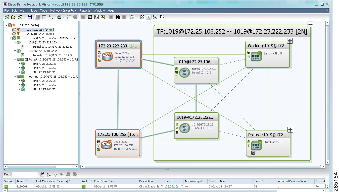
In Figure 17-1:
•
•
•
•
•
–
–
–
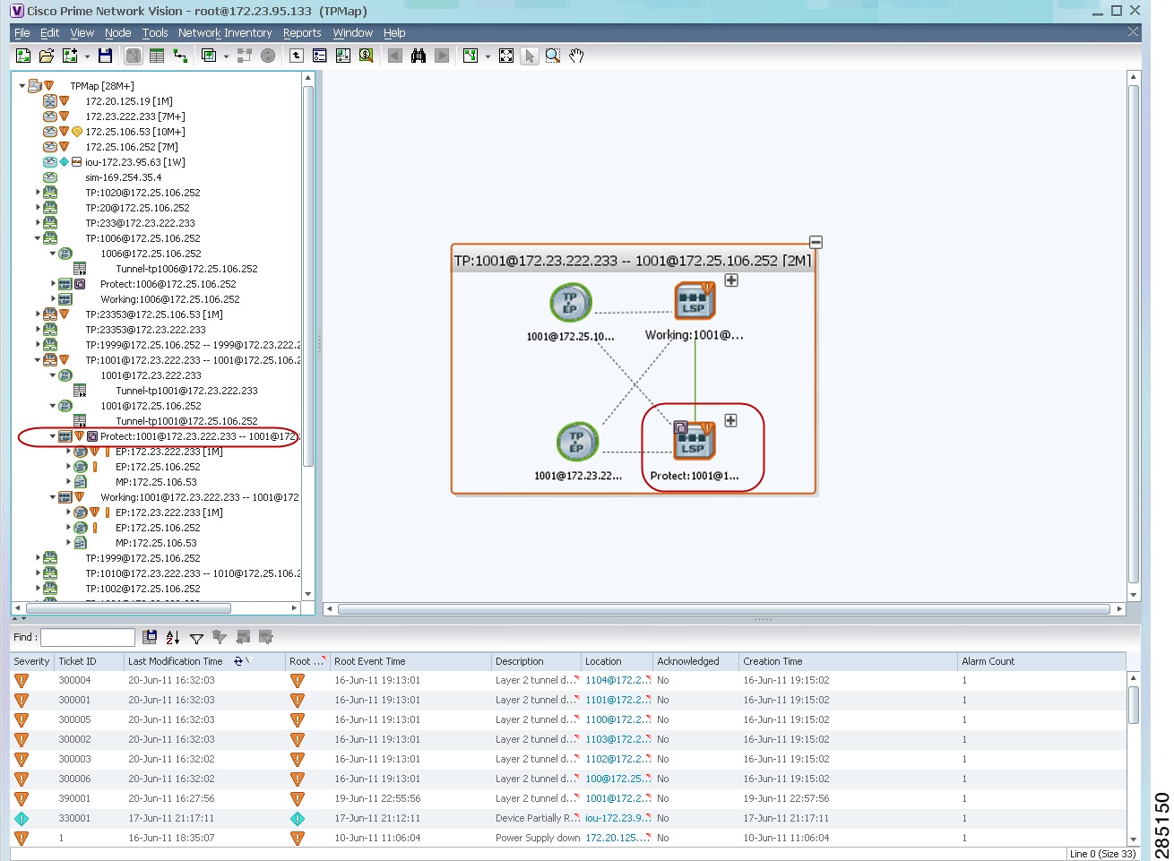
Figure 17-1 MPLS-TP Tunnel in Prime Network Vision Map
If an LSP is in lockout state, it is displayed with the lock badge (
).
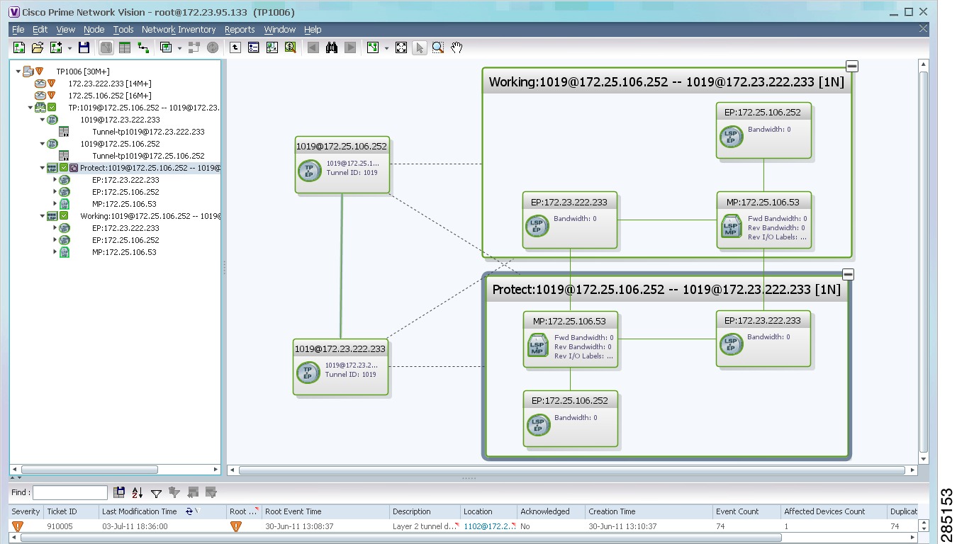
By expanding all aggregations in the MPLS-TP tunnel (see Figure 17-2), you can see components and links in the MPLS-TP tunnel, including:
•
•
•
Figure 17-2 MPLS-TP Tunnel Expanded
If an LSP is configured for redundancy service, a redundancy service badge is applied to the secondary (backup) LSP in the navigation and map panes in the navigation and map panes.
For more information about LSP redundancy service, see Viewing LSP Endpoint Redundancy Service Properties.
Viewing MPLS-TP Tunnel Properties
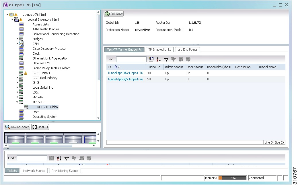
Prime Network Vision discovers and displays MPLS-TP attributes in the MPLS-TP branch in logical inventory as described in this topic.
Additional information about MPLS-TP tunnel properties are available in the following branches:
•
•
•
To view MPLS-TP tunnel properties:
Step 1
Step 2
The routing information is displayed as shown in Figure 17-3.
Figure 17-3 MPLS-TP Tunnel Properties in Logical Inventory
Table 17-3 describes the information that is available for MPLS-TP tunnels. The information that is displayed depends on the configuration.
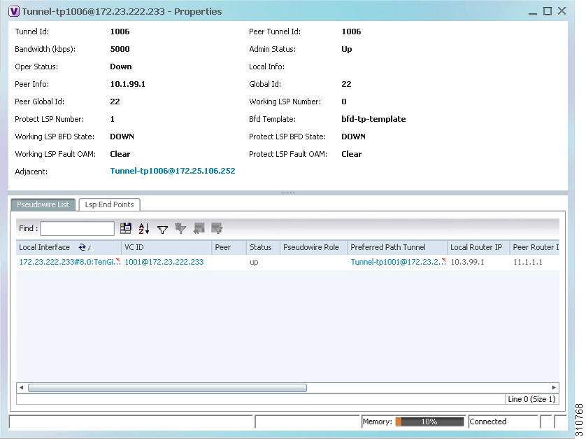
Step 3
The MPLS-TP Tunnel Properties window is displayed as shown in Figure 17-4.
Figure 17-4 MPLS-TP Tunnel Properties Window
Table 17-4 describes the information available in the top portion of the MPLS-TP Tunnel Properties window. For information about the tabs that are displayed, see Table 17-3.
Viewing LSPs Configured on an Ethernet Link
A single Ethernet link can support a number of LSPs. Prime Network Vision enables you to view all LSPs on a single Ethernet link and to identify the source and destination labels.
To view LSPs configured on an Ethernet link:
Step 1
Step 2
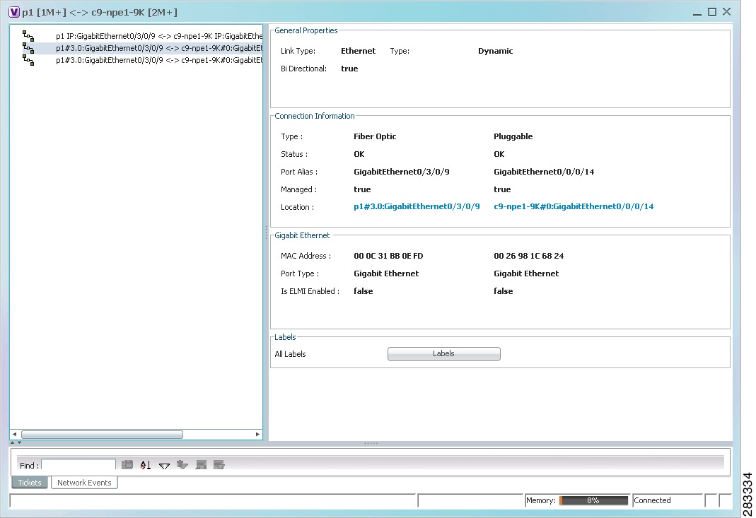
The link properties window refreshes and displays the Labels button as shown in Figure 17-5.
Figure 17-5 Link Properties Window with All Labels Button
Step 3
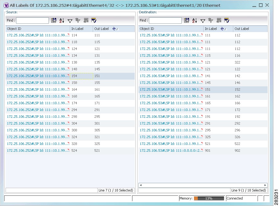
The All Labels window is displayed as shown in Figure 17-6 with the LSP sources and destinations.
Figure 17-6 All Labels Table
Step 4
Viewing LSP Endpoint Redundancy Service Properties
If an LSP endpoint in an MPLS-TP tunnel is configured for redundancy service, a redundancy service badge is applied to the secondary (backup) LSP endpoint in the navigation and map panes in Prime Network Vision. Additional redundancy service details are provided in the LSP endpoint properties window and the inventory window for the element on which the MPLS-TP tunnel is configured.
To view LSP endpoint redundancy service properties:
Step 1
If the LSP endpoint is configured for redundancy service, the redundancy service badge is displayed in the navigation and map panes as shown in Figure 17-7.
Figure 17-7 LSP Endpoint with Redundancy Service Badge
Step 2
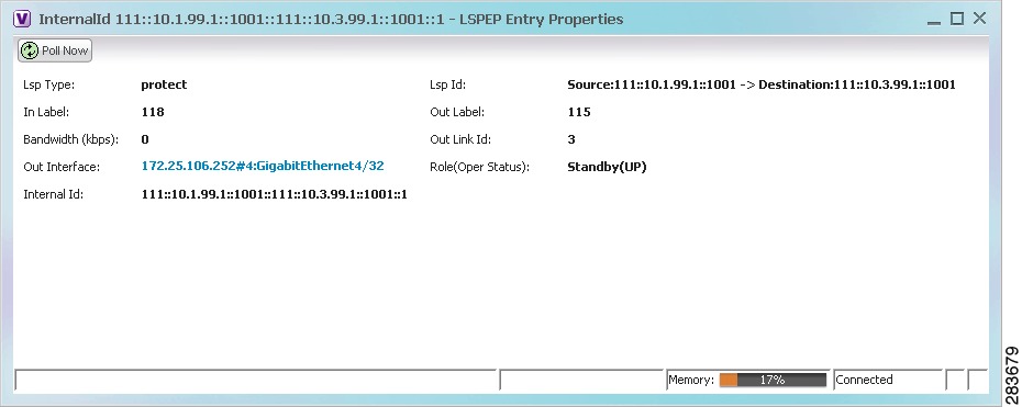
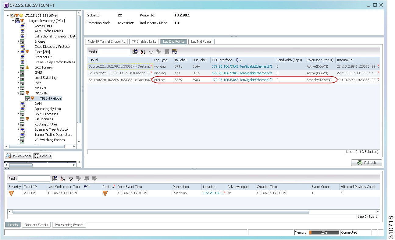
The LSP endpoint properties window is displayed as shown in Figure 17-8.
Figure 17-8 LSP Endpoint Properties Window
Table 17-5 describes the information displayed in the LSP Endpoint Properties window.
Step 3
Step 4
Step 5
•
•
•
Figure 17-9 LSP End Points Tab in Logical Inventory
Applying an MPLS-TP Tunnel Overlay
You can select and display an overlay of a specific MPLS-TP tunnel on top of the devices displayed in a map view. The overlay is a snapshot of the network that visualizes the flows between the sites and tunnel peers. When an MPLS-TP tunnel is selected in the map, the following elements are highlighted in the map:
•
•
All elements and links that are not part of the MPLS-TP tunnel are dimmed.
To apply an MPLS-TP tunnel overlay:
Step 1
Step 2
The Select MPLS-TP tunnel Overlay dialog box is displayed.
Step 3
•
–
–
–
The search condition is "contains." Search strings are case-insensitive. For example, if you choose the Name category and enter "net," Prime Network Vision displays MPLS-TP tunnels that have "net" in their names whether net appears at the beginning of the name, the middle, or at the end: for example, Ethernet.
•
Step 4
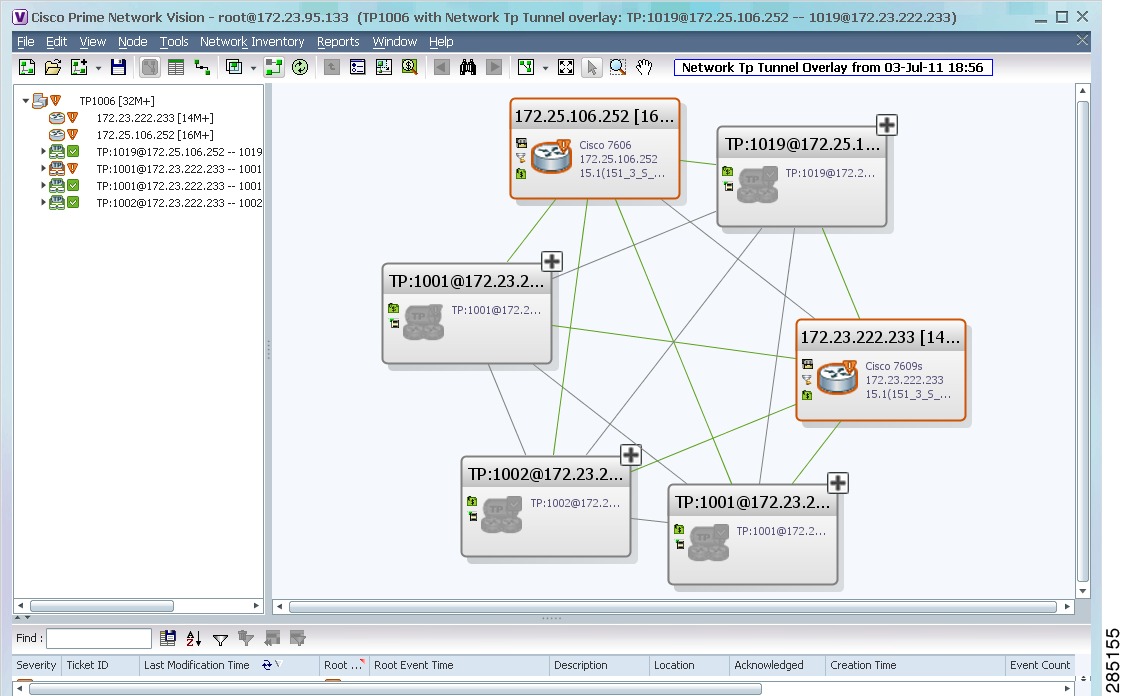
The elements and links used by the selected MPLS-TP tunnel are highlighted in the network map, and the MPLS-TP tunnel name is displayed in the window title bar as shown in Figure 17-10.
Figure 17-10 MPLS-TP Tunnel Overlay
Note
Viewing VPNs
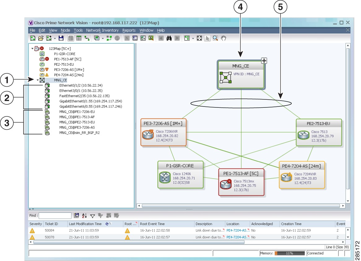
Figure 17-11 shows a VPN displayed in the Prime Network Vision map view. In this example, the VPN is selected in the navigation pane, so the VPN details, such as virtual routers and IP interfaces, are not shown in the map view.
Figure 17-11 VPN in Prime Network Vision Map View
VPN in the navigation tree
VPN in the map view
Sites
VPN links (IPv4 and IPv6 aware)
Virtual routers
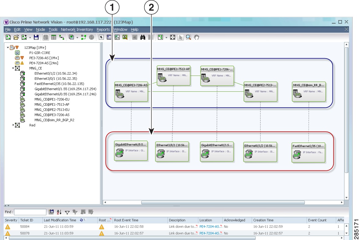
Figure 17-12 shows a VPN with details, including virtual routers and sites, in the Prime Network Vision map view.
Figure 17-12 VPN in Prime Network Vision Map View with VRFs and Sites
The Prime Network Vision navigation pane displays the VPN business elements in a tree-and-branch representation. Each business element is represented by an icon in a color that reflects the highest alarm severity. The icon might also have a management state badge or alarm. For more information about icon severity colors and badges, see Prime Network Vision Status Indicators.
Table 17-6 shows the VPN icons in the Prime Network Vision map view.
Table 17-6 VPN Icons in Prime Network Vision Map View
Root (map name) or aggregation
VPN
Virtual router
Site
The highest level of the navigation pane displays the root or map name. The branches display the VPN and aggregated business elements as well as their names. The Layer 3 VPN sub-branch displays the virtual routers and sites contained in the VPN along with the names of the business elements. In addition, CE devices can be displayed in the Layer 2 and Layer 3 VPN sub-branches. If you select an aggregated business element in the navigation pane, the map view displays the business elements contained within the aggregated business element.
The Prime Network Vision map view displays the VPN business elements and aggregated business elements loaded in the map view, along with the names of the business elements. In addition, the map view displays the VPN topology (between the virtual routers in the VPNs) and the topology and associations between other business elements. After you select the root in the navigation pane, the map view displays all the VPNs.
Prime Network Vision presents tickets related to the map in the ticket area, which allows you to view and manage the VPN tickets.
Viewing Additional VPN Properties
Prime Network Vision allows you to select any element in the navigation pane or map view and view additional underlying properties. To view additional properties for an object, either double-click it or right-click it and choose Properties. Table 17-7 shows the additional properties available for VPN entities.
Managing VPNs
The following topics describe:
•
Creating a VPN
You can change business configurations by manually creating VPNs. The VPNs that are manually created do not contain virtual routers and sites.
To create a VPN:
Step 1
Step 2
Step 3
•
Note
•
Note
•
Step 4
The new VPN is added to the VPN list in the Add VPN dialog box.
For more information about loading the newly created VPN in the service view map, see Adding a VPN to a Map.
Adding a VPN to a Map
You can add a VPN to a map view if the VPN was previously created by a user or discovered by Prime Network Vision and are not currently displayed in the map.
Note
To add an existing VPN to a map:
Step 1
Step 2
•
•
The Add VPN dialog box is displayed.
Step 3
•
–
–
The search condition is "contains." Search strings are case-insensitive. For example, if you choose the Name category and enter "net," Prime Network Vision displays VPNs that have "net" in their names whether at the beginning of the name, the middle, or the end.
•
Step 4
Tip
Step 5
The VPN is displayed in the navigation pane and the selected map or subnetwork in the Prime Network Vision window content pane. In addition, any tickets are displayed in the ticket area.
Removing a VPN from a Map
You can remove one or more VPNs from the current active map. This change does not affect other maps. Removing a VPN from a map does not remove it from the Prime Network Vision database. The VPN will appear in the Add VPN dialog box, so you can add it back to the map at any time.
When removing VPNs from maps, keep the following in mind:
•
•
•
To remove a VPN, in the Prime Network Vision pane or map view, right-click the VPN and choose Remove from Map.
The VPN is removed from the map view along with all VPN elements, such as connected CE devices. Remote VPNs (extranets) are not removed.
Note
Moving a Virtual Router Between VPNs
You can move a virtual router (including its sites) from one VPN to another after you create a VPN and add it to the service view map.
Note
To move a virtual router:
Step 1
Step 2
Caution
The virtual router and its sites are displayed under the selected VPN in the navigation pane and in the map.
Working with VPN Overlays
The following topics describe:
•
•
Applying VPN Overlays
You can select and display an overlay of a specific VPN on top of the devices displayed in a map view. The overlay is a snapshot of the network that visualizes the flows between the sites and tunnel peers. When one network VPN is selected in the network map, the PE routers, MPLS routers, and physical links that carry the LSP used by the VPN are highlighted in the network map. All the devices and links that are not part of the VPN are dimmed.
The VPN service overlay allows you to isolate the parts of a network that are being used by a particular service. This information can then be used for troubleshooting. For example, the overlay can highlight configuration or design problems when bottlenecks occur and all the site interlinks use the same link.
To apply a VPN overlay:
Step 1
Step 2
The Select VPN Overlay dialog box is displayed.
Step 3
•
–
–
The search condition is "contains." Search strings are case-insensitive. For example, if you choose the Name category and enter "net," Prime Network Vision displays VPNs that have "net" in their names whether net appears at the beginning of the name, the middle, or at the end: for example, Ethernet.
•
Step 4
The PE routers, MPLS routers, and physical links used by the selected VPN are highlighted in the network map. The VPN name is displayed in the title of the window.
Note
Managing a VPN Overlay Display in the Map View
After a VPN overlay is applied to a map, you can manage its display by using the overlay tools in the main toolbar:
•
•
Note
•
Displaying VPN Callouts in a VPN Overlay
You can display or hide the callouts for VPN links displayed in a VPN overlay to show the details of the sites that are interlinked through the selected links. The callouts (see Figure 17-13) enable you to view the VPN traffic links for a specific link (either bidirectional or unidirectional).
Note
Figure 17-13 Callouts Window
To display or hide the callouts:
Step 1
Step 2
Step 3
Monitoring MPLS Services
The following topics provide details for viewing MPLS services and technologies:
•
•
•
•
•
•
Viewing VPN Properties
To view the properties of a VPN:
Step 1
•
•
The VPN Properties window displays the following information:
•
•
Step 2
Viewing Site Properties
Prime Network Vision enables you to view site properties, including the interfaces that are configured on the PE device. The displayed properties reflect the configuration that Prime Network Vision automatically discovered for the device.
To view site properties, in the Prime Network Vision navigation pane or map view, right-click the required site and choose Properties.
Table 17-8 describes the information that is displayed in the Router IP Interface Properties window:
Table 17-8 Router IP Interface Properties Window for Sites
Name
Name of the site, such as FastEthernet4/1.252.
State
Interface state, either Up or Down.
IP Address
IP address of the interface.
Mask
Network mask.
Interface Description
Description applied to the interface.
Associated Entity
Element and interface associated with the site, hyperlinked to its entry in physical inventory.
Subnet
IP address and subnet mask.
Note
Type
Address type, such as Primary, Secondary, or IPv6 Unicast.
Viewing VRF Properties
Prime Network Vision enables you to view VRF properties, including the VRF route distinguisher, import and export route targets, and any provisioned sites and VRF routes.
To view VRF properties, do either of the following in map view:
•
•
The VRF properties window is displayed as shown in Figure 17-14.
Figure 17-14 VRF Properties
The VRF Properties window contains the VRF routing table for the device. The table is a collection of routes that are available or reachable to all the destinations or networks in the VRF. The forwarding table also contains MPLS encapsulation information.
Table 17-9 describes the information displayed in the VRF Properties window.
Note
Table 17-9 VRF Properties
Route Distinguisher
Name
VRF name.
Description
Description of the VRF.
Export Route Targets
IPv4 export route targets contained by the VRF.
Import Route Targets
IPv4 import route targets contained by the VRF.
Route Maps
Route maps for the VRF.
Export Route Targets
IPv6 export route targets contained by the VRF.
Import Route Targets
IPv6 import route targets contained by the VRF.
Route Maps
Route maps for the VRF.
Destination
Destination of the specific network.
Prefix Length
Length of the network prefix in bits.
Next Hop
Next routing hop.
Outgoing Interface
Name of the outgoing interface; displayed if the Routing Protocol type is local.
Type
Route type: Direct (local), Indirect, or Static.
Routing Protocol
Routing protocol used to communicate with the other sites and VRFs: BGP or local.
BGP Next Hop
Border Gateway Protocol (BGP) next hop. This is the PE address from which to continue to get to a specific address. This field is empty when the routing entry goes to the CE.
Bottom In Label
Innermost label that is expected when MPLS traffic is received.
Bottom Out Label
Innermost label sent with MPLS traffic.
Outer Label
Outermost or top label in the stack used for MPLS traffic.
Name
Site name.
IP Address
IP address of the interface.
Mask
Subnet mask.
State
State of the subinterface: Up or Down.
Associated Entity
Element and interface associated with the site, hyperlinked to its entry in physical inventory.
Description
Interface description.
Input Access List
Access list applied to the inbound traffic.
Output Access List
Access list applied to the outbound traffic.
Rate Limits
If a rate limit is configured on an IP interface, the limit is shown as an IP interface property. This option is checked when a rate limit is defined on the IP interface, meaning the access list is a rate limit access list. IP interface traffic is measured and includes the average rate, normal burst size, excess burst size, conform action, and exceed action.
Note
Note
IP Sec Map Name
IP Security (IPsec) map name.
Site Name
Name of the business element to which the interface is attached.
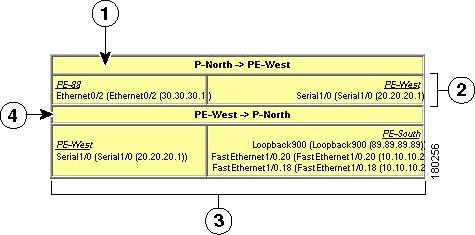
Viewing VRF Egress and Ingress Adjacents
Prime Network Vision enables you to view the exporting and importing neighbors by displaying the VRF egress and ingress adjacents. In addition, you can view the connectivity between the VRFs for the route targets and view their properties. For example, if VRF A retrieved route target import X, you can view all VRFs that export X as a route target whether it is in the same or another VPN.
To display the VRF egress and ingress adjacents, you can use either an element configured for VRFs or a virtual router:
•
a.
b.
c.
•
Table 17-10 describes the information displayed in the Adjacents window.
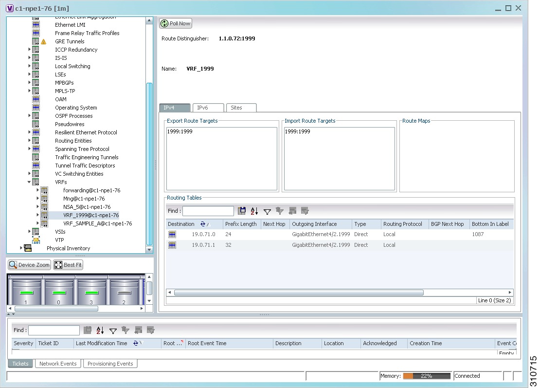
Viewing Routing Entities
To view routing entities:
Step 1
Step 2
The routing information is displayed as shown in Figure 17-15.
Figure 17-15 Routing Entity Table
Table 17-11 describes the information that is displayed in the Routing Entity table.
Table 17-11 Routing Entity Table
Name
Name of the routing entity.
Name
Site name.
IP Address
IP address of the interface.
Mask
Network mask.
State
State of the subinterface: Up or Down.
Associated Entity
Interface associated with the routing entity, hyperlinked to its location in physical inventory.
Description
Description of the interface.
Input Access List
If an input access list is assigned to an IP interface, the list is shown as an IP interface property, and a hyperlink highlights the related access list in the Access List table. When an access list is assigned to the inbound traffic on an IP interface, the actions assigned to the packet are performed.
VRRP Group
If a VRRP group is configured on an IP interface, the information is shown as an IP interface property. This option is checked when a rate limit is defined on the IP interface.
Note
Output Access List
If an output access list is assigned to an IP interface, the list is shown as an IP interface property, and a hyperlink highlights the related access list in the Access List table. When an access list is assigned to the outbound traffic on an IP interface, the actions assigned to the packet are performed.
Rate Limits
If a rate limit is configured on an IP interface, the limit is shown as an IP interface property. This option is checked when a rate limit is defined on the IP interface, meaning the access list is a rate limit access list. IP interface traffic is measured and includes the average rate, normal burst size, excess burst size, conform action, and exceed action.
Note
Note
IP Sec Map Name
IP Security (IPsec) crypto map name.
Site Name
Name of the business element to which the interface is attached.
Destination
Destination of the specific network.
Outgoing If Name
Name of the outgoing interface; displayed if the Routing Protocol type is local.
Type
Routing type: Direct, Indirect, Static, Other, Invalid, or Unknown.
Next Hop
IP address from which to continue to get to a specific address. This field is empty when the routing entry goes to a PE router.
Prefix Length
Length of the network prefix in bits.
Route Protocol Type
Routing protocol used to communicate with other routers.
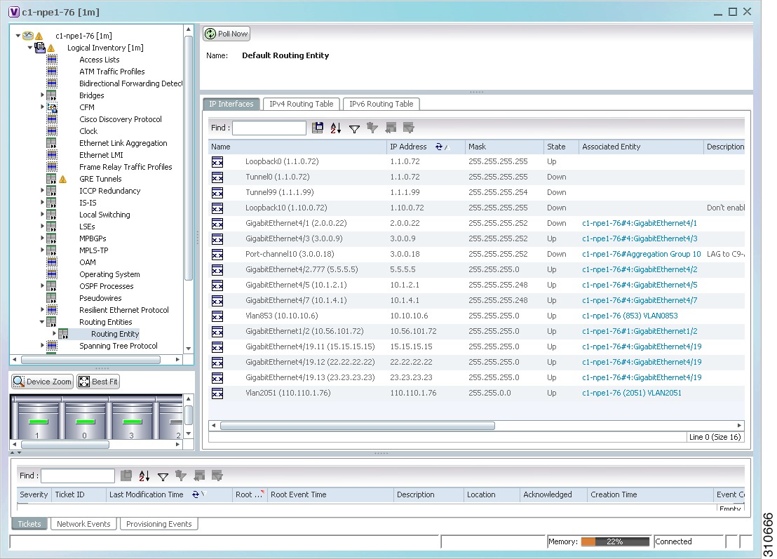
Viewing the ARP Table
To view the ARP table:
Step 1
Step 2
Table 17-12 describes the information that is displayed in the ARP table.
Viewing the NDP Table
Neighbor Discovery Protocol (NDP) is used with IPv6 to discover other nodes, determine the link layer addresses of other nodes, find available routers, and maintain reachability information about the paths to other active neighbor nodes.
NDP functionality includes:
•
•
•
•
•
•
To view the NDP table:
Step 1
Step 2
Step 3
Figure 17-16 shows an example of the NDP Table tab.
Figure 17-16 NDP Table in Logical Inventory
Table 17-13 describes the information displayed for NDP.
Viewing Rate Limit Information
To view rate limit information:
Step 1
Step 2
Step 3
Note
Table 17-14 describes the information that is displayed in the Rate Limits tab of the IP Interface Properties dialog box.
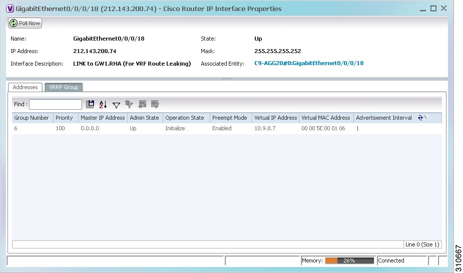
Viewing VRRP Information
Virtual Router Redundancy Protocol (VRRP) is a non-proprietary redundancy protocol that is designed to increase the availability of the static default gateway servicing hosts on the same subnet. This increased reliability is achieved by advertising a virtual router (a representation of master and backup routers acting as a group) as a default gateway to the hosts instead of one physical router. Two or more physical routers are then configured to stand for the virtual router, with only one doing the actual routing at any given time. If the current physical router that is routing the data on behalf of the virtual router fails, another physical router automatically replaces it. The physical router that forwards data on behalf of the virtual router is called the master router; physical routers standing by to take over for the master router if needed are called backup routers.
To view VRRP information:
Step 1
Step 2
Step 3
Figure 17-17 VRRP Properties in IP Interface Properties Window
Table 17-15 describes the information in the VRRP Groups tab.
Viewing Label Switched Entity Properties
Logical inventory can display any or all of the following tabs for label switched entities, depending on the configuration:
•
•
Two LDP peer discovery types are supported:
–
–
If two LSRs are connected with two separate interfaces, two LDP discoveries are performed.
•
•
•
•
To view information for label switched entities:
Step 1
Step 2
Table 17-16 describes the information that is displayed for label switched entities.
Step 3
Viewing MP-BGP Information
The MP-BGP branch displays information about a router's BGP neighbors and cross-connect VRFs.
Note
To view MP-BGP information:
Step 1
Step 2
Table 17-18 describes the information that is displayed for MP-BGP.
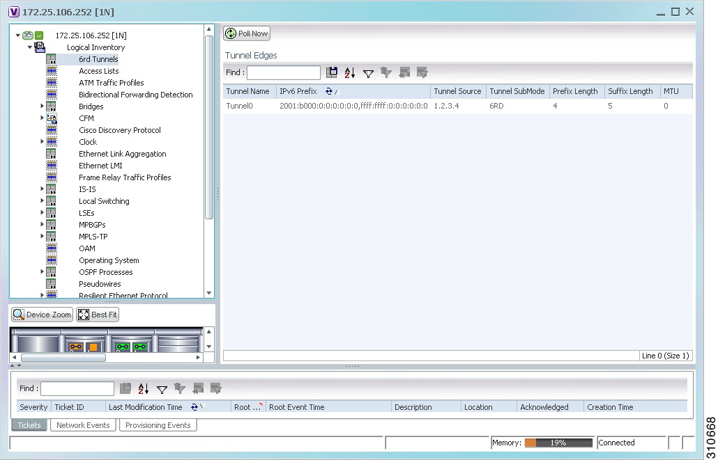
Viewing 6rd Tunnel Properties
IPv6 rapid deployment (6rd) is a mechanism that allows stateless tunneling of IPv6 over IPv4. From Prime Network Vision 3.8, 6rd is supported on the following devices:
•
•
To view 6rd tunnel properties:
Step 1
Step 2
The 6rd tunnel properties are displayed as shown in Figure 17-18.
Figure 17-18 6rd Tunnel Properties in Logical Inventory
Table 17-19 describes the information displayed for 6rd tunnels.
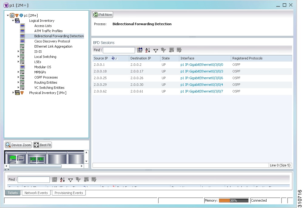
Viewing BFD Session Properties
Bidirectional Forwarding Detection (BFD) is used to detect communication failures between two elements, or endpoints, that are connected by a link, such as a virtual circuit, tunnel, or LSP. BFD establishes sessions between the two endpoints over the link. If more than one link exists, BFD establishes a session for each link.
Prime Network Vision supports BFD with the following protocols: BGP, IPv4 (static), IPv6 (static), IS-IS, LAG (Ether channel), MPLS TE, MPLS-TP, and OSPF.
To view BFD session properties that are configured on an element:
Step 1
Step 2
The properties for BFD sessions are displayed as shown in Figure 17-19.
Figure 17-19 BFD Session Properties
Table 17-20 describes the information displayed for BFD sessions.
For MPLS-TP BFD sessions, the information in Table 17-21 is displayed.
Step 3
Table 17-22 describes the information that is displayed in the Session Properties window.
Viewing Cross-VRF Routing Entries
Cross-VRF routing entries display routing information learned from the BGP neighbors (BGP knowledge base).
To view properties for cross-VRF routing entries:
Step 1
Step 2
Step 3
Step 4
The Cross VRF Properties window is displayed, containing the information described in Table 17-23.
Viewing Pseudowire End-to-End Emulation Tunnels
The Pseudowires branch in logical inventory displays a list of the Layer 2 tunnel edge properties (per edge), including tunnel status and VC labels.
To view pseudowire properties:
Step 1
Step 2
The Tunnel Edges table is displayed and contains the information described in Table 17-24.
Viewing MPLS TE Tunnel Information
Prime Network Vision automatically discovers MPLS TE tunnels and enables you to view MPLS TE tunnel information in inventory.
To view MPLS TE tunnel information:
Step 1
Step 2
Table 17-25 describes the information that is displayed in the Tunnel Edges table.
The Traffic Engineering LSPs tab in the LSEs branch in logical inventory displays TE tunnel LSP information.
For details about the information displayed for TE tunnel LSPs, see Traffic Engineering LSPs.