-
Cisco Prime Network User Guide, 3.9
-
Preface
-
Cisco Prime Network Client Overview
-
Working with the Cisco Prime Network Vision Client
-
Viewing Network Element Properties
-
Working with Prime Network Vision Maps
-
Working with Links
-
Working with Business Tags and Business Elements
-
Working with the Prime Network Events Client
-
Tracking Faults Using Prime Network Events
-
Working with Tickets in Cisco Prime Network Vision
-
Working with Reports
-
Using Cisco PathTracer to Diagnose Problems
-
Monitoring Carrier Ethernet Services
-
Monitoring Carrier Grade NAT Properties
-
Monitoring DWDM Properties
-
Viewing Ethernet Operations, Administration, and Maintenance Tool Properties
-
IPv6 and IPv6 VPN over MPLS
-
Monitoring MPLS Services
-
Monitoring MToP Services
-
Viewing SBC Properties
-
Viewing Mobile Technologies in Prime Network
-
Icon and Button Reference
-
Index
-
 Feedback
Table Of Contents
Using Cisco PathTracer to Diagnose Problems
User Roles Required to Work with Cisco PathTracer
Cisco PathTracer Right-Click Menu Options
From Logical or Physical Inventory
Examples of Launching Cisco PathTracer
Viewing Path Traces in Cisco PathTracer
Cisco PathTracer Details Window Toolbar
Saving and Opening Cisco PathTracer Map Files
Saving Cisco PathTracer Counter Values
Rerunning a Path and Comparing Results
Viewing Q-in-Q Path Information
Using Cisco PathTracer in MPLS Networks
Cisco PathTracer MPLS Start and Endpoints
Using Cisco PathTracer for CSC Configurations
Using Cisco PathTracer for Layer 3 VPNs
Using Cisco PathTracer for Layer 2 VPNs
Using Cisco PathTracer for MPLS TE Tunnels
Using Cisco PathTracer to Diagnose Problems
Cisco PathTracer enables you to view a network path between two network objects. The following topics describe Cisco PathTracer and how to use it:
•
User Roles Required to Work with Cisco PathTracer
•
•
•
•
•
•
•
User Roles Required to Work with Cisco PathTracer
This topic identifies the roles that are required to work with Cisco PathTracer. Cisco Prime Network (Prime Network) determines whether you are authorized to perform a task as follows:
•
•
For more information on user authorization, see the Cisco Prime Network 3.9 Administrator Guide.
The following tables identify the tasks that you can perform:
•
•
By default, users with the Administrator role have access to all managed elements. To change the Administrator user scope, see the topic on device scopes in the Cisco Prime Network 3.9 Administrator Guide.
Cisco PathTracer Overview
Cisco PathTracer enables you to launch end-to-end route traces and view related performance information for Layer 1, Layer 2, and Layer 3 traffic. Upon receiving a path's start and endpoint, Cisco PathTracer visually traces the route through the network. For example, in an ATM network environment, Cisco PathTracer identifies all information regarding the connection of a subscriber to a provider, including all ATM PVCs, ATM switching tables, ATM class of service (CoS) definitions, IP-related information, and so on.
You can also use Cisco PathTracer to:
•
•
•
In MPLS and Carrier Ethernet environments, Cisco PathTracer can trace paths across:
•
•
•
•
•
In addition, Cisco PathTracer can trace a path:
•
•
Prime Network derives the various paths on the network from its up-to-date knowledge of the network. After a user selects a source and destination, Cisco PathTracer finds and retrieves the path of a specified service, and displays the path in the Cisco PathTracer window. The retrieved information contains network elements in the path, including all properties at Layer 1, Layer 2, and Layer 3, plus alarm information, counters, and more, all of which is available via Cisco PathTracer.
Launching Path Traces
Cisco PathTracer can be launched from a bridge, switching entity, Ethernet interface, Ethernet flow point, VLAN interface, ATM VC, DLCI, or IP interface entry point. Ethernet flow points can be starting points whether they are associated with an interface, bridge, or LAG.
The virtual route is found according to the cross connect table of each ATM switch or Frame Relay device. The IP routing and path-finding process is enabled according to the VRF tables of each router, and the Ethernet-simulated path is found according to the various Layer 2 forwarding tables, such as bridges or VSIs.
To view a specific path, you must specify an initial point and a destination, such as an IP or MAC address. If you specify VC or DLCI information, which ends in a router, Cisco PathTracer finds the next hop according to the destination IP address. If you do not specify a destination IP or MAC address, Cisco PathTracer uses the default gateway in the router. Any business tags that are associated with the physical or logical entities are also displayed.
Note
Path Traces and Blocked Ports
The following conditions apply for blocked ports:
•
•
•
Table 11-3 identifies the available path trace launching points and their locations within Cisco Prime Network Vision. Cisco PathTracer is available in each location as a right-click menu option.
Cisco PathTracer Right-Click Menu Options
Cisco PathTracer is launched by using right-click menu options. Table 11-3 identifies the launching points for the different types of elements.
Starting a Path Trace
You can start a path trace in the following ways:
•
From the Map View
To start a path trace from the map view:
Step 1
•
a. In the navigation pane or map pane, select the required network VLAN.
b. Double-click the VLAN to view the VLAN entities.
c. Right-click the required item and choose PathTracer > From Here to Destination or PathTracer > Start Here.
•
a. In the navigation pane or map pane, select the required network VPN.
b. Double-click the VPN to view the VPN entities.
c. Right-click the site and choose PathTracer > From Here to Destination or PathTracer > Start Here.
•
a. Choose Network Inventory > Ethernet Flow Domains.
b. In the Ethernet Flow Domain List Properties window, double-click the required domain.
c. In the Ethernet Flow Domain Properties window, right-click the required element and choose PathTracer > From Here to Destination or PathTracer > Start Here.
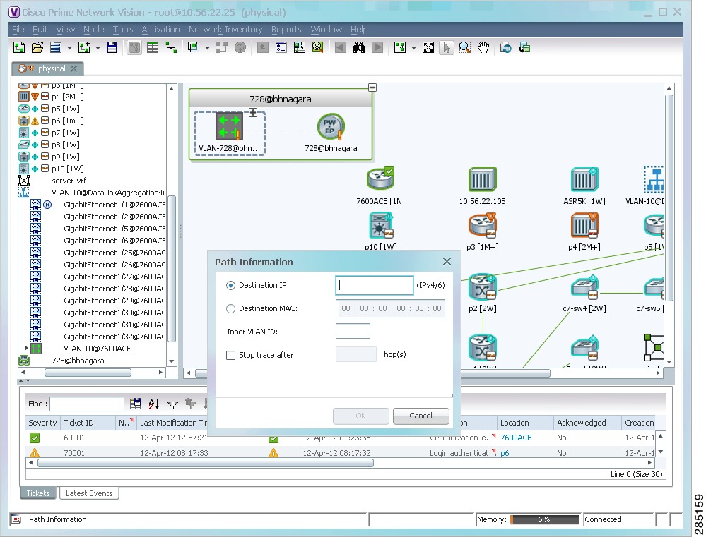
The next step depends on your choice in Step 1:
•
•
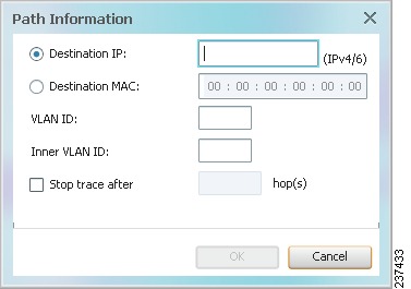
Figure 11-1 Path Information Dialog Box
Step 2
a.
Depending on the launch point, the Path Information dialog box might not contain all of the fields in Table 11-4.
b.
Step 3
The Cisco PathTracer window is displayed showing the path or paths that were found.
Step 4
Step 5
•
•
For more information about the end-to-end path and networking layer details, see Viewing Path Trace Details.
From Logical or Physical Inventory
To start a path trace from logical or physical inventory:
Step 1
Step 2
•
•
•
•
•
Step 3
•
Note
•
Examples of Launching Cisco PathTracer
The following topics provide examples for launching Cisco PathTracer from different locations in Cisco Prime Network Vision:
•
Using an Ethernet Flow Point
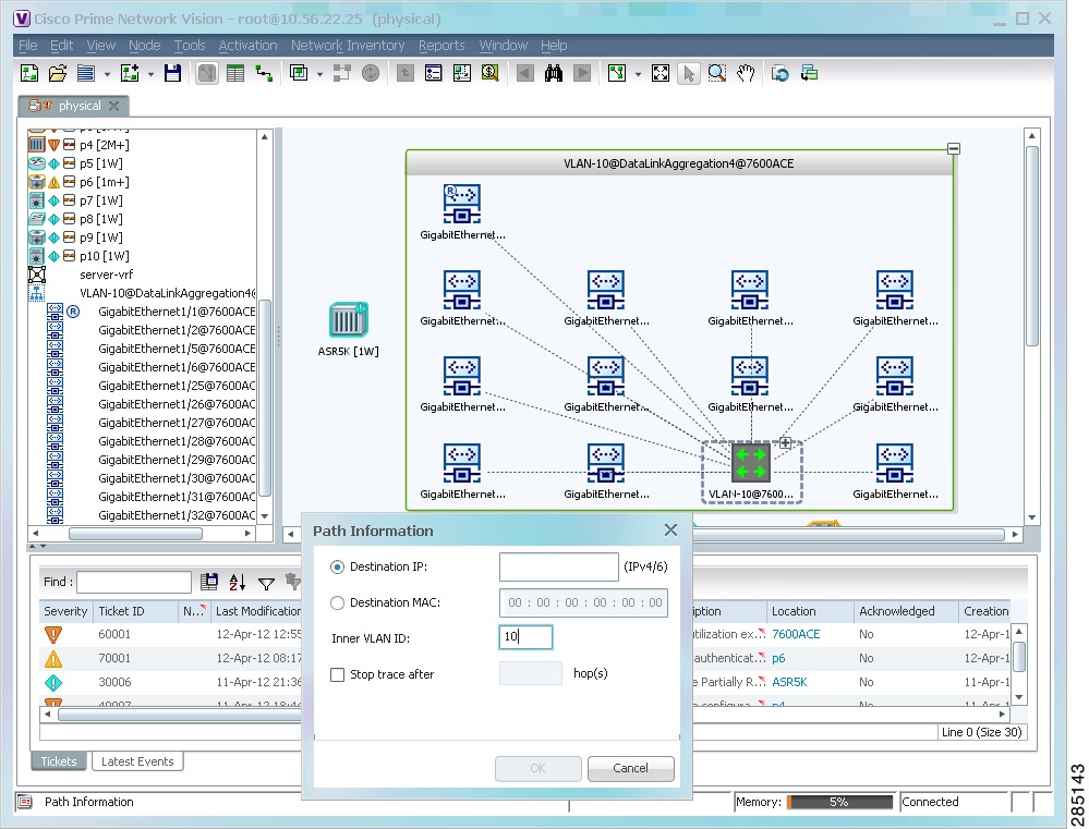
A network VLAN is required for you to start a path trace using an Ethernet flow point.
To launch a path trace from an Ethernet flow point:
Step 1
Step 2
Figure 11-2 Ethernet Flow Point Path Trace Launch Point
Step 3
Step 4
Step 5
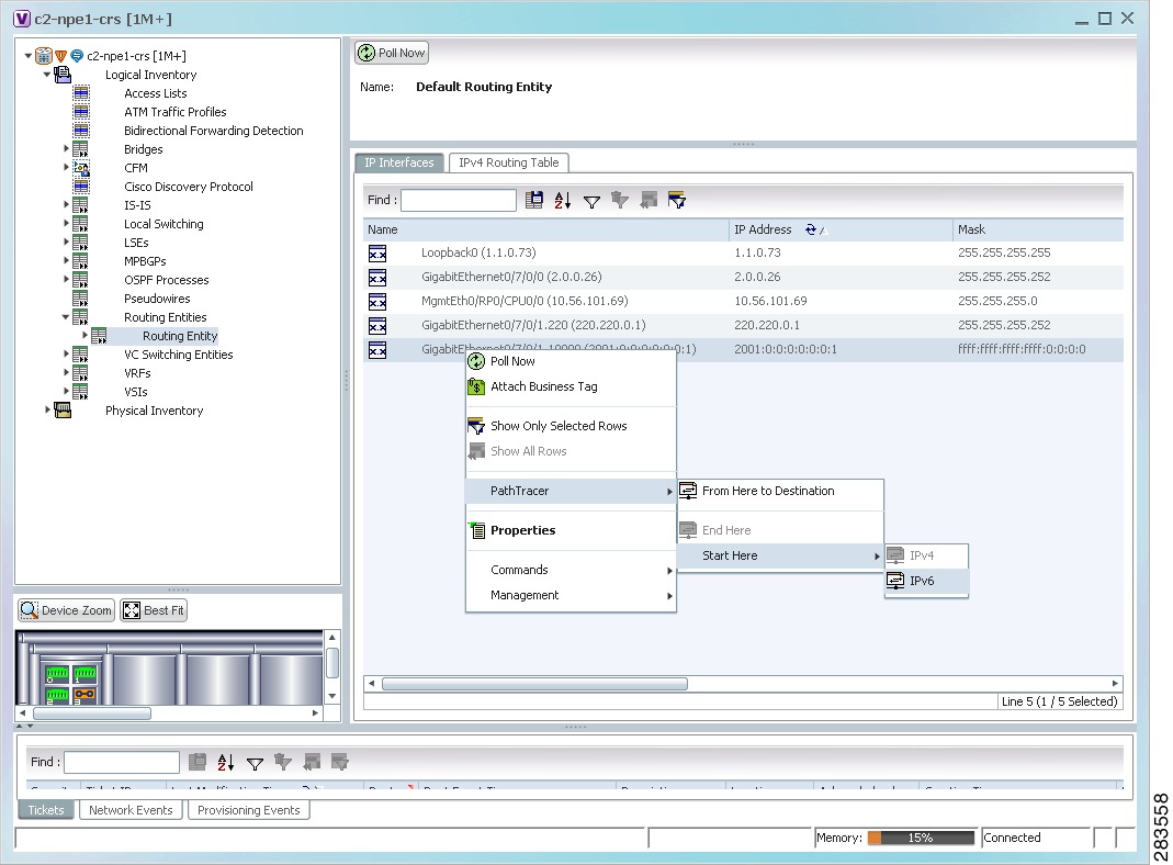
Using an IP Interface
Both IPv4 and IPv6 addresses are supported as valid path trace sources and destinations as illustrated in the following procedure.
To launch a path trace from an IP interface:
Step 1
The right-click menu displays IPv4 and IPv6 options. These options are enabled or dimmed, depending on whether the IP interface has an IPv4 address, an IPv6 address, or both IPv4 and IPv6 addresses. See Figure 11-3.
Figure 11-3 IP Interface Path Trace Launch Point - Right-Click Menu
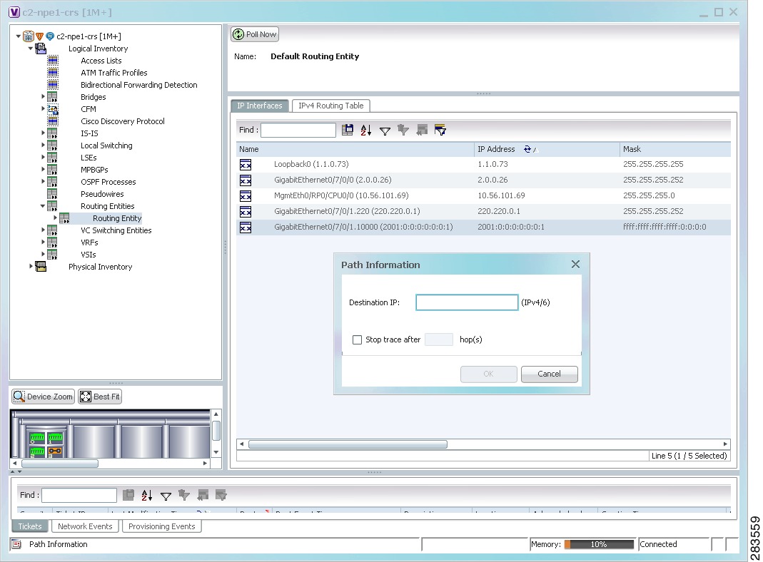
Step 2
The Path Information dialog box is displayed as shown in Figure 11-4.
Figure 11-4 IP Interface Path Trace Launch Point - Path Information Dialog Box
Step 3
Step 4
Step 5
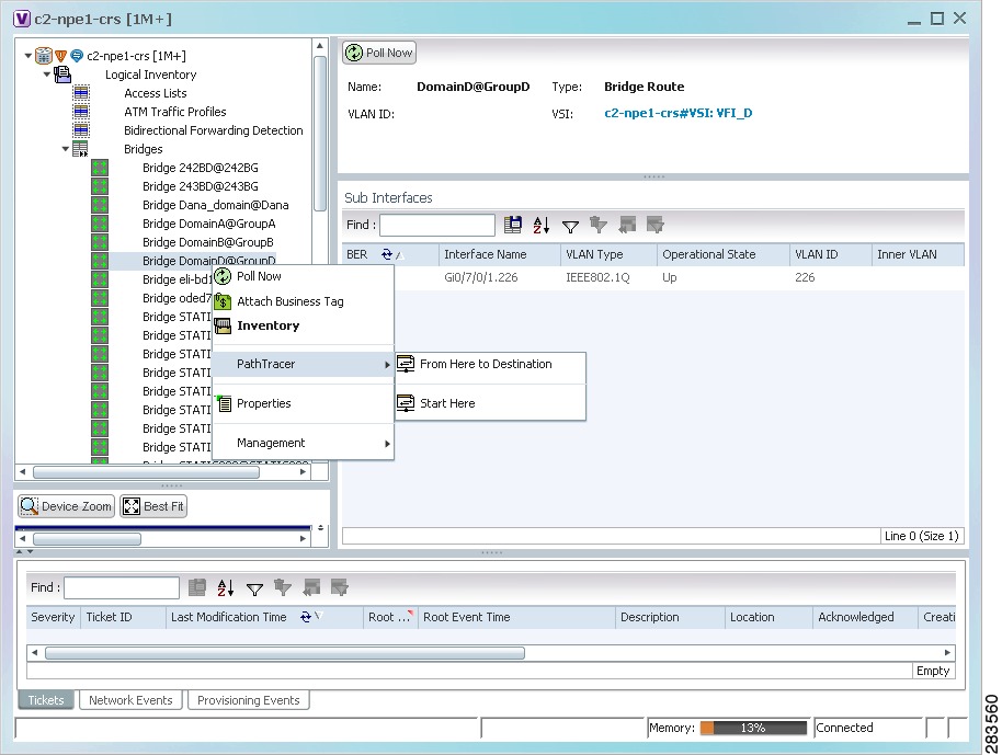
Using a VLAN Bridge
You can launch path traces from VLAN bridges. Additionally, MAC addresses in the VLAN bridge forwarding table can be path trace destinations.
To launch a path trace from a VLAN bridge:
Step 1
•
•
Figure 11-5 VLAN Bridge Path Trace Launch Point
Step 2
Step 3
•
•
•
•
When a destination is selected, the system extracts the relevant IP address from this point and uses it as the destination.
The Cisco PathTracer window is displayed with the resulting path trace.
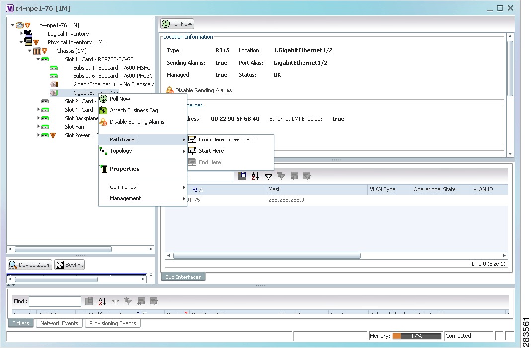
Using an Ethernet Port
To launch a path trace from an Ethernet port:
Step 1
•
•
Figure 11-6 Ethernet Port Path Trace Launch Point
Step 2
The Cisco PathTracer window appears, displaying the resulting path trace.
Using a Pseudowire
To launch a path trace from a network pseudowire endpoint:
Step 1
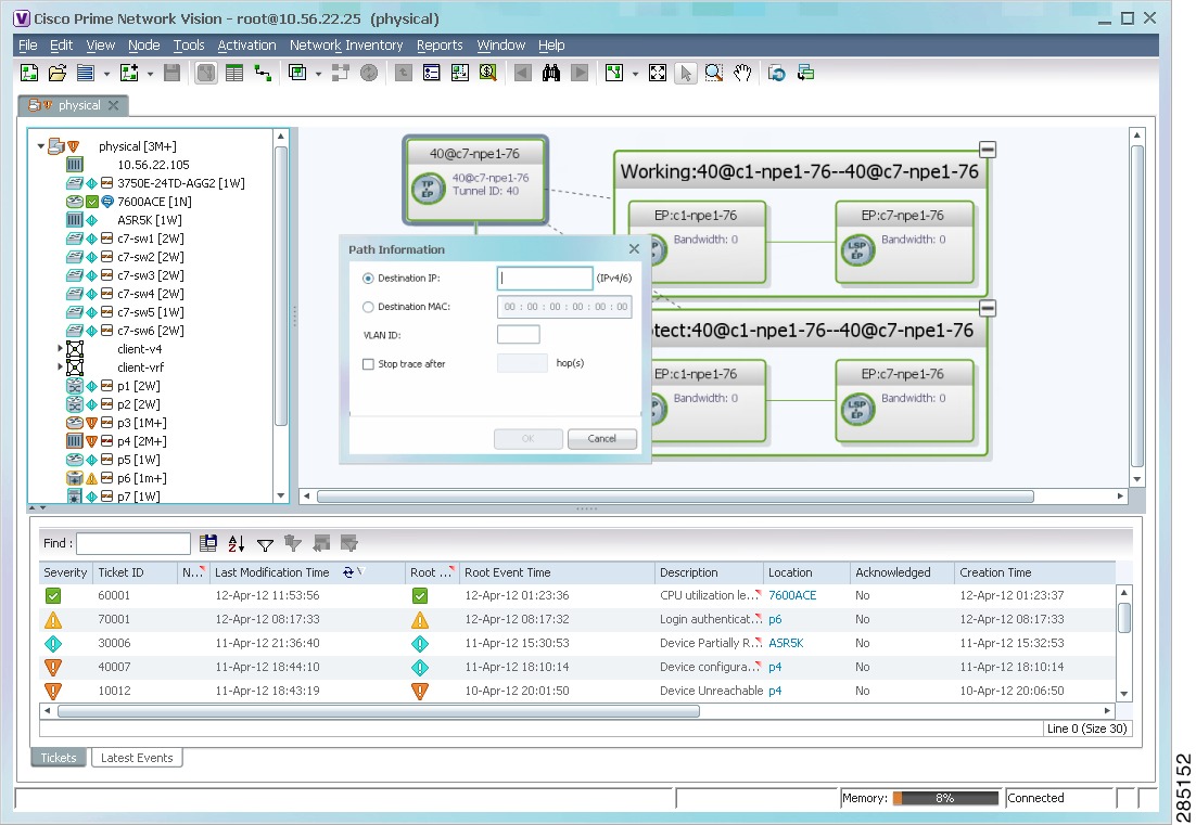
Step 2
The Path Information dialog box is displayed as shown in Figure 11-7.
Figure 11-7 Path Information Dialog Box for a Network Pseudowire
Step 3
Step 4
The Cisco PathTracer window appears, displaying the resulting path trace.
Using an MPLS-TP Tunnel Endpoint
To launch a path trace from an MPLS-TP tunnel endpoint:
Step 1
Step 2
The Path Information dialog box is displayed as shown in Figure 11-8.
Figure 11-8 MPLS-TP Tunnel Endpoint Path Trace Launch
Step 3
Step 4
The Cisco PathTracer window appears, displaying the resulting path trace.
Viewing Path Traces in Cisco PathTracer
The Cisco PathTracer window displays all discovered paths for the specified source and destination of the path trace, including the devices and physical links.
In addition, the Cisco PathTracer window enables you to:
•
•
•
•
You can also right-click elements in the Cisco PathTracer window and choose options from a right-click menu. The right-click menu is context sensitive depending on the view and the item selected. For more information about the right-click menu and the available options, see Right-Click Menu Options.
The Cisco PathTracer window enables you to:
•
•
•
•
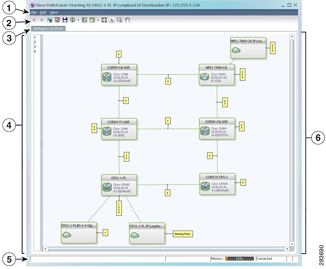
Figure 11-9 shows an example of the Cisco PathTracer window with a multiple-path trace.
Figure 11-9 Cisco PathTracer Window - Multiple-Path Trace
The Cisco PathTracer window contains the following components and options:
Menus
Table 11-5 describes the options available in the Cisco PathTracer menus.
Toolbar
Table 11-6 describes the options available in the Cisco PathTracer toolbar.
Table 11-6 Cisco PathTracer Toolbar Options
Displays the previous path in the path trace pane.
Displays the next path in the path trace pane.
Clears the path selection made in the path trace pane.
Opens the Cisco PathTracer details window. A map is displayed for the selected path, including network element details, links, and property information. For more information, see Viewing Path Trace Details.
Saves the current multiple-path trace to an XML file on your local system. For more information, see Saving and Opening Cisco PathTracer Map Files.
Offers the following options for running Cisco PathTracer again for the same source and destination:
•
•
•
The new path trace map is displayed in the path trace pane.
A new tab with the up-to-date (or refreshed) path map is created for each run, with each tab representing a run and the tab label indicating the snapshot time.
Opens a window displaying a high level view of the path trace currently displayed in the path trace pane.
Specifies how the elements are arranged in the path trace pane: circular, hierarchical, orthogonal, or symmetric.
Fits the entire path trace in the path trace pane.
Activates the normal selection mode. The button toggles when selected or deselected.
Activates the zoom selection mode, which enables you to select a specific area in the path to zoom in on by clicking and dragging. The button toggles when selected or deselected.
Activates the pan mode, which enables you to move around in the path trace by clicking and dragging. The button toggles when selected or deselected.
Trace Tabs
The discovered path trace is initially displayed in the path trace pane with a tab that displays the date and time when Prime Network started the path tracing process (snapshot time).
If you load a saved path from a file or run the displayed path trace again, the opened or refreshed path is displayed in a new tab with a refreshed path map for each run or file. When using a saved path from a file, the source and destination must be the same as the current display for it to appear in the same path trace window. Each tab represents a run or file, and its header displays the snapshot time.
Paths Pane
The paths pane lists all the paths discovered in the current path trace. A new path is created for each source and destination pair. The paths are identified by number, such as 1, 2, and 3.
If you launch a path trace with a specific hop count, the paths pane displays First n Hops where n is the number of hops specified.
Selecting a path in the paths pane highlights the selected path in the path trace pane. The paths that are not selected are dimmed in the map.
To view a different path, do either of the following:
•
•
To remove a path selection, click Clear Path Selection in the toolbar.
Path Trace Pane
The path trace pane displays the devices, links, and topological paths that are part of the path trace. All links and nodes in the path trace pane are labeled with their relevant path numbers, corresponding to the numbers in the paths pane. The starting point is labeled with a Starting Point callout. All other edge points are displayed as clouds.
The same coloring conventions that are used for links in the Prime Network content pane are used to display links in the Cisco PathTracer path trace pane.
Cisco PathTracer uses icons to display the network objects and their status. The status of a network object can be indicated on the topological map in the following ways:
•
•
•
For more information, see:
•
•
Right-Click Menu Options
You can right-click network elements in the path trace window and choose items from a right-click menu. The right-click menu is context sensitive depending on the view and the element selected.
Table 11-7 describes the right-click menu options that are available for elements selected in the Cisco PathTracer window.
Table 11-7 Cisco PathTracer Element Right-Click Menu Options
Inventory
Opens the inventory window for the selected element.
Aggregate
Groups the selected devices into an aggregation.
Disaggregate
Ungroups the devices in the selected aggregation.
Note
Poll Now
Polls the selected element.
Attach Business Tag
Attaches a business tag to the selected network element
Config Mgmnt
This option is available only if Prime Network Change and Configuration Management is installed.
Displays the Configuration Management page for the selected device in Prime Network Change and Configuration Management.
Image Mgmnt
This option is available only if Prime Network Change and Configuration Management is installed.
Displays the Configuration Management page for the selected device in Prime Network Change and Configuration Management.
Resize
Enables you to resize an object on the map by percentage or size.
Open Relevant Maps
Displays the Open Map dialog box so that you can view and open maps that contain the selected element.
Run Report
Enables you to run standard or user-defined events, inventory, and network service reports on demand.
Show Callouts/
Hide CalloutsDisplays or hides callouts associated with the selected element.
Tools
Contains the following choices:
•
•
•
Note
- For Windows 7 32-bit systems, enable the Windows Telnet Client to use the Prime Network Vision Telnet option.
- For Windows 7 64-bit systems, a solution is available on the Cisco Developer Network at http://developer.cisco.com/web/ana/forums/-/message_boards/message/2780108.Topology
Enables you to add:
•
•
•
Launch external applications
Starts an external application or tool that has been configured for access via the right-click menu. For more information, see the Cisco Prime Network 3.9 Customization User Guide.
Properties
Displays the properties of the selected item, such as the IP address and system name.
Commands
Launches available activation and configuration scripts. This can include the commands documented in Commands part of the Cisco Prime Network 3.9 Reference Guide, and those you create using Command Builder. For more information, see the Cisco Prime Network 3.9 Customization User Guide.
Management
Contains the following submenu options:
•
•
VNE Tools
Contains the following submenu options:
•
•
•
Viewing Path Trace Details
In addition to the information displayed in the Cisco PathTracer window, you can:
•
–
–
–
•
•
To view this information, select the required path in the Cisco PathTracer window, and then click PathTracer in the toolbar. If you select multiple paths, a separate window is opened for each path.
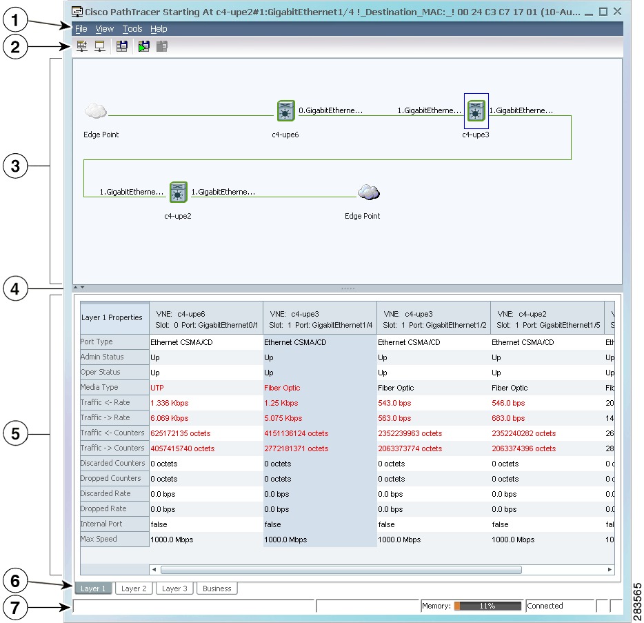
Figure 11-10 shows an example of the Cisco PathTracer details window.
Figure 11-10 Cisco PathTracer Details Window
Menu bar
Details pane
Toolbar
Layer and Business tabs
Path trace pane
Status bar
Hide/display path trace pane
The Cisco PathTracer details window contains the following components:
•
Menus
Table 11-8 describes the Cisco PathTracer details window menu options.
Cisco PathTracer Details Window Toolbar
Table 11-9 describes the tools that are available in the Cisco PathTracer details window toolbar.
Path Trace Pane
The path trace pane in the Cisco PathTracer details window displays information related to the tab selected in the details pane. For example, if you choose the Layer 2 tab in the details pane, Layer 2 information is displayed in the path trace pane. Similarly, if you choose an element or link in the path trace pane, the related parameters are highlighted in the details pane.
By default, the path trace pane includes:
•
•
•
Hovering your mouse over an element displays a tooltip that contains the element name, device type, and IP address. Hovering your mouse over the link to the right or left of the element displays the associated incoming or outgoing interface for that element and link.
Table 11-10 describes the right-click menu options that are available for elements in the path trace pane.
Table 11-10 Cisco PathTracer Element Right-Click Menu Options
Inventory
Opens the inventory window for the selected element.
Attach Business Tag
Attaches a business tag to the selected network element
Poll Now
Polls the selected element.
Config Mgmnt
This option is available only if Prime Network Change and Configuration Management is installed.
Displays the Configuration Management page for the selected device in Prime Network Change and Configuration Management.
Image Mgmnt
This option is available only if Prime Network Change and Configuration Management is installed.
Displays the Configuration Management page for the selected device in Prime Network Change and Configuration Management.
Run Report
Enables you to run standard or user-defined events, inventory, and network service reports on demand.
Tools
Contains the following choices:
•
•
•
Note
- For Windows 7 32-bit systems, enable the Windows Telnet Client to use the Prime Network Vision Telnet option.
- For Windows 7 64-bit systems, a solution is available on the Cisco Developer Network at http://developer.cisco.com/web/ana/forums/-/message_boards/message/2780108.Topology
Enables you to add:
•
•
•
Launch external applications
Starts an external application or tool that has been configured for access via the right-click menu. For more information, see the Cisco Prime Network 3.9 Customization User Guide.
Properties
Displays the properties of the selected item, such as the IP address and system name.
Commands
Launches available activation and configuration scripts. This can include the commands documented in Commands part of the Cisco Prime Network 3.9 Reference Guide, and those you create using using Command Builder. For more information, see the Cisco Prime Network 3.9 Customization User Guide.
Management
Contains the following submenu options:
•
•
VNE Tools
Contains the following submenu options:
•
•
•
Details Pane
Selecting a device or link in the path trace pane automatically highlights the related parameters in the details pane.
The details pane, with its Layer and Business tabs, displays the supported parameters of the selected element in a table, with the ingress and egress ports along the top and the parameters on the left.
Any inconsistencies between the two connected ports are colored to emphasize a discrepancy, such as different admin statuses.
The information parameters are arranged as follows:
•
–
–
–
If a field has no value on any of the interfaces, the field is not displayed in the table. For example, if none of the interfaces is configured for MTU, the MTU row is not displayed in the table. If at least one of the interfaces is configured for MTU, the MTU row is displayed.
•
Saving and Opening Cisco PathTracer Map Files
Prime Network enables you to export multiple-path trace maps that are displayed in the Cisco PathTracer window to an XML file. You can view the data later to assess whether anything has changed.
Saving Cisco PathTracer Map Files
To save Cisco PathTracer map files:
Step 1
Step 2
Step 3
Step 4
Opening Cisco PathTracer Map Files
Prime Network enables you to open saved XML-formatted path-tracing maps.
The following conditions apply when working with multiple-path trace files:
•
•
To open Cisco PathTracer map files:
Step 1
Step 2
Step 3
Saving Cisco PathTracer Counter Values
Prime Network enables you to export, over a period of time, the counter values of the path displayed in the Cisco PathTracer window to a CSV file. The data can then be viewed later, as required.
Note
To save Cisco PathTracer counter values that are generated over a period of time:
Step 1
Step 2
Step 3
Step 4
Step 5
Step 6
Cisco PathTracer stops exporting the counter values to the file.
Rerunning a Path and Comparing Results
If you save a path to a file (see Saving and Opening Cisco PathTracer Map Files), you can use the file to rerun the same path automatically with the same source and destination. You can also compare the saved path to a newly run path to determine if the path has changed or to assess a problem.
To rerun a saved path:
Step 1
Step 2
The path trace runs automatically using the same source and destination as the loaded map file, and a new tab is displayed in the Cisco PathTracer window with the updated map. The tab displays the date and time when the path was rerun.
Step 3
Note
•
Viewing Q-in-Q Path Information
The Q-in-Q (IEEE 802.1) tagging technology (also known as Dot1q tunneling) allows the nesting of another VLAN tag in a packet, in addition to an existing one. Either VLAN tag is considered an 802.1Q header.
Cisco PathTracer uses the VLAN tags of the Ethernet header and the port configuration to trace the path from one interface to another over the network. Among other things, you can:
•
•
Q-in-Q and Dot1q information is displayed in the Cisco PathTracer window when a path is traced over Ethernet ports with Dot1q and a Q-in-Q configuration.
As described in Launching Path Traces, to view a specific path, you must specify an initial start point, such as an IP interface, and then an endpoint, such as a destination IP address.
To trace a Q-in-Q path, you start the path from any:
•
•
After you select the endpoint, the Cisco PathTracer window is displayed. From this window, you can open the Cisco PathTracer details window, with the appropriate Q-in-Q information displayed in the Layer 2 tab.
The Layer 2 tab can display the following information specific to Q-in-Q and VLAN port configurations:
•
•
–
–
•
•
Viewing L2TP Path Information
Cisco PathTracer uses VC ID encapsulation information to trace the path from one tunnel interface to another over the network. The Cisco PathTracer tool enables you to:
•
•
The Layer 3 tab displays the peer name for L2TP tunnels.
Table 11-11 describes the information that is displayed in the Layer 2 tab for L2TP tunnels.
Using Cisco PathTracer in MPLS Networks
You can open and view Cisco PathTracer information between service endpoints, such as an IP interface that is attached to the VRF over an MPLS network. The LSP in the MPLS network is found according to the cross-connect table of each router.
Note
To view a specific path, you must specify an initial starting point, such as an IP interface; specifying a destination IP address is optional. If the traced path (for example, a VC or VLAN) ends in a router, Cisco PathTracer finds the next hop according to the destination IP address. If you select an endpoint, Cisco PathTracer extracts the relevant IP address from this point and uses it as the destination.
The following topics provide more information on using Cisco PathTracer in MPLS networks:
•
•
•
•
•
Cisco PathTracer MPLS Start and Endpoints
You can open Cisco PathTracer by right-clicking a starting point and entering the required destination IP address. Table 11-12 lists the Cisco PathTracer starting points.
If you choose the Start Here option, Table 11-13 lists the endpoints that can be selected as path destinations.
The Cisco PathTracer window is displayed. From this window you can open the Cisco PathTracer details window with the VPN information displayed in the Layer 2 and Layer 3 tabs.
Note
Using Cisco PathTracer for CSC Configurations
Cisco PathTracer traces a CSC flow from the customer CE through the customer carrier VPN, across the customer backbone carrier VPN, back to the customer carrier VPN, and to the destination CE.
To launch a path trace for a CSC configuration:
Step 1
Step 2
Step 3
Step 4
Step 5
Step 6
The path trace is displayed in the Cisco PathTracer window.
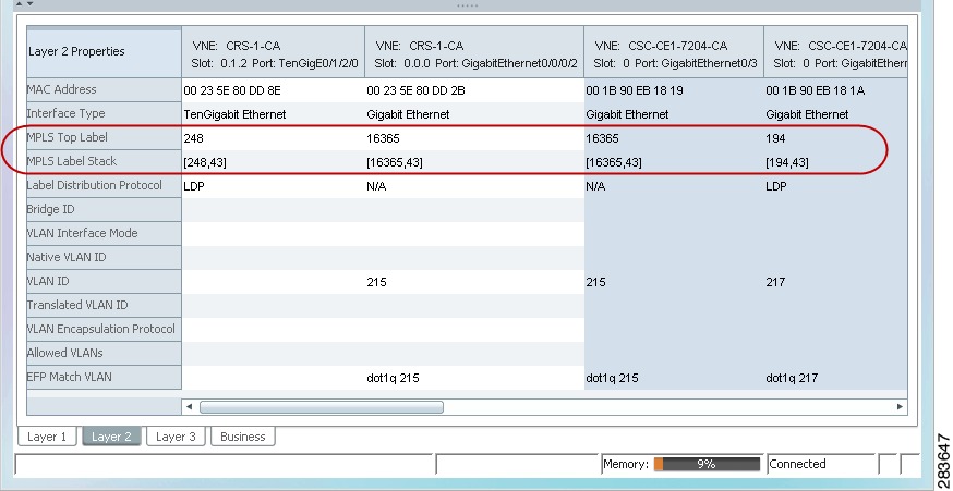
Step 7
The Layer 2 tab displays a single outer label and two inner labels for each interface, reflecting the CSC configuration. (See Figure 11-11.)
Figure 11-11 CSC Configuration Path Trace
Using Cisco PathTracer for Layer 3 VPNs
Cisco PathTracer uses VRF routing and label switching information to trace the path from one VRF interface to another. If you choose a launch point and destination from the right-click menu, you can open the Cisco PathTracer for Layer 3 VPNs. The Cisco PathTracer window shows the VPN topology map. From this window, you can open the Cisco PathTracer details window with the appropriate VPN information displayed in the Layer 2 and Layer 3 tabs.
For Layer 3 path information, Prime Network uses VRF routing and label switching information to trace the path from one VRF interface to another. Layer 3 path trace information is displayed in the Cisco PathTracer window when the path goes over connections and ends in VRFs.
If a VRF table includes more than one path toward a destination, Cisco PathTracer shows all paths.
To view Layer 3 path information, choose the Layer 3 tab and choose Show All from the View menu. The path information is displayed in the active tab.
The table displays the Layer 3 VPN information on the device that has a VRF. The following Layer 3 properties displayed in the Layer 3 tab relate specifically to VPNs:
•
•
•
•
•
Cisco PathTracer does not display or trace EXP bits for Layer 3 VPNs that use policy-based tunnel selection (PBTS).
Using Cisco PathTracer for Layer 2 VPNs
Cisco PathTracer uses VC ID and label switching information to trace the path from one tunnel interface to another over the MPLS network.
Cisco PathTracer also covers end-to-end Layer 2 VPN service paths from one CE router to another. The path goes over circuits (such as a VC) or VLANs in access networks and over LSP between the Layer 2 tunnel edge.
The Cisco PathTracer window shows the VPN topology map for the relevant devices and links. From this window, you can open the Cisco PathTracer details window with the appropriate VPN information displayed in the Layer 2 and Layer 3 tabs.
For Layer 2 path information, Cisco PathTracer uses VC ID and label switching information to trace the path from one tunnel interface to another. Layer 2 path trace information is displayed in the Cisco PathTracer window when the path goes over pseudowire tunnels.
To view Layer 2 path information, choose the Layer 2 tab and then View > Show All. The path information is displayed in the active tab.
Table 11-14 describes the Layer 2 properties that can be displayed in the Layer 2 tab specifically for VPNs.
Using Cisco PathTracer for MPLS TE Tunnels
Cisco PathTracer uses label switching information to trace the end-to-end path of a TE tunnel path from one PE router to another.
Using MPLS TE technology, Cisco PathTracer enables you to:
•
•
–
–
The Cisco PathTracer window is displayed showing the MPLS TE tunnel topology map. From this window, you can open the Cisco PathTracer details window with the appropriate MPLS TE tunnel information displayed in the Layer 2 tab.
Note
Layer 2 and Layer 3 path trace information is displayed in the Cisco PathTracer details window when a path is traced over MPLS TE tunnels. To view Layer 2 path information, choose the Layer 2 tab and then View > Show All. The path information is displayed in the active tab.
Table 11-15 describes the Layer 2 properties that can be displayed in the Layer 2 tab specifically for MPLS TE tunnels.
Table 11-15 Cisco PathTracer Layer 2 Properties for MPLS TE Tunnels
MPLS TE Properties
MPLS TE data set in an MPLS interface, primarily bandwidth allocation levels and signaling protocol.
Tunnel Oper Status
Operational status of the tunnel: Up or Down.
If this value is Up, the Tunnel Admin Status must also be Up. See Tunnel Admin Status properties for additional information.
Tunnel Bandwidth Kbps
Configured bandwidth (in Kb/s) for the tunnel.
Tunnel Description
Description of the tunnel.
Tunnel Name
Interface name.
Tunnel Admin Status
Administrative status of the tunnel (Up or Down) with the following caveats:
•
•
Tunnel Lockdown
Whether or not the tunnel can be rerouted:
•
•
Tunnel LSP ID
LSP identifier.
Tunnel Auto Route
Whether or not destinations behind the tunnel are routed through the tunnel: Enabled or disabled.
Tunnel Hold Priority
Tunnel priority after path setup.
Tunnel Setup Priority
Tunnel priority upon path setup.
Tunnel Path Option
Tunnel path option:
•
•
Tunnel Out Label
TE tunnel MPLS label distinguishing the LSP selection in the adjacent device.
Tunnel Affinity
Tunnel's preferential bits for specific links.
Tunnel Destination Address
IP address of the device in which the tunnel ends.
Tunnel Peak Rate Kbps
Peak flow specification (in Kb/s) for this tunnel.
Tunnel Out Interface
Interface through which the tunnel exits the device.
Tunnel Burst Kbps
Burst flow specification (in Kb/s) for this tunnel.
Tunnel Average Rate Kbps
Tunnel average rate in Kb/s.
Tunnel Affinity Mask
Tunnel affinity bits that should be compared to the link attribute bits.