-
Cisco IP Solution Center MPLS VPN User Guide, 4.1
-
Index
-
Preface
-
Getting Started
-
Provisioning Unmanaged Multi-VRF CE
-
Creating Resource Pools
-
Defining VPNs and CERCs
-
MPLS VPN Service Policies
-
MPLS VPN Service Requests
-
Provisioning Regular PE-CE Links
-
Provisioning MVRFCE PE-CE Links
-
Provisioning Management VPN
-
Provisioning Cable Services
-
Provisioning Carrier Supporting Carrier
-
Provisioning Multiple Devices
-
Spanning Multiple Autonomous Systems
-
Creating Custom MPLS Reports
-
IP Solution Center - MPLS VPN
-
Service Request Transition States
-
Troubleshooting MPLS VPN
-
 Feedback
Table Of Contents
Service Request Transition States
How ISC Accesses Network Devices
Creating a PE-CE Service Request
Creating a Multi-VRF Service Request
Creating an Multi-VRFCE PE-CE Service Request
Creating a PE-Only Service Request
How to Perform a Functional Audit
Where to Find the Functional Audit
Why a Functional Audit Could Fail
How to Perform a Configuration Audit
Where to Find the Configuration Audit
Why a Configuration Audit Could Fail
MPLS VPN Service Requests
This chapter describes how to provision and audit service requests in IP Solution Center (ISC). This chapter contains the following major sections:
Overview of Service Requests
This section contains the following sections:
•
Service Request Transition States
•
Service Request Transition States
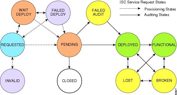
The focus of ISC is the service provided for a customer on the link between a customer CE and a provider PE. The service request model is the centerpiece of service provisioning. With the service request model, the ISC can capture the specified VPN service provisioning request, analyze the validity of the request, and audit the provisioning results.
The service provider operators take all service request information from their customers. ISC can assist the operator in making entries because the product has customer information such as the VPN information, the list of the assigned PEs and CEs, and so forth.
ISC steps the operator through the process and simplifies the task of provisioning the CE and PE by automating most of the tasks required to set up an MPLS VPN.
Figure 6-1 shows a high-level diagram of the relationships and movement among ISC service request states. For a description of the service request transition sequences, see "Service Request Transition States."
Figure 6-1 Service Request States: Movement and Relationships
Table 6-1, "Summary of Cisco IP Solution Center Service Request States," describes each of the service request states and their transition sequences.
Service Enhancements
With this release of MPLS VPN Management, a number of enhancements to the service function are available:
•
•
A multicast address is a single address that represents a group of machines. Unlike a broadcast address, however, the machines using a multicast address have all expressed a desire to receive the messages sent to the address. A message sent to the broadcast address is received by all IP-speaking machines, whether they care what it contains or not. For example, some routing protocols use multicast addresses as the destination for their periodic routing messages. This allows machines that have no interest in routing updates to ignore them.
To implement multicast routing, ISC employs the concept of a multicast domain (MD), which is a set of VRFs associated with interfaces that can send multicast traffic to each other. A VRF contains VPN routing and forwarding information for unicast. To support multicast routing, a VRF also contains multicast routing and forwarding information; this is called a Multicast VRF.
•
Although a route target provides the mechanisms to identify which VRFs should receive routes, a route target does not provide a facility that can prevent routing loops. These routing loops can occur if routes learned from a site are advertised back to that site. To prevent this, the Site of Origin (SOO) feature identifies which site originated the route, and therefore, which site should not receive the route from any other PE routers.
•
•
How ISC Accesses Network Devices
When ISC attempts to access a router, it uses the following algorithm:
1.
2.
3.
If any step in the VPN Solutions Center device-access algorithm fails, the entire device access operation fails—there is no retry or rollover operation in place. For example, if there is a terminal server and ISC encounters an error in attempting to access the target device through the terminal server, the access operation fails at that point. With the failure of the terminal server access method, ISC does not attempt to find the management interface to access the target device.
Creating Service Requests
A service request is an instance of service contract between a customer edge router (CE) and a provider edge router (PE). The service request user interface asks you to enter several parameters, including the specific interfaces on the CE and PE routers, routing protocol information, and IP addressing information.
You can also integrate an ISC template with a service request, and associate one or more templates to the CE and the PE.
To create a service request, a Service Policy must already be defined, as described in "MPLS VPN Service Requests."
This section has the following sections:
•
•
•
MPLS VPN Topology Example
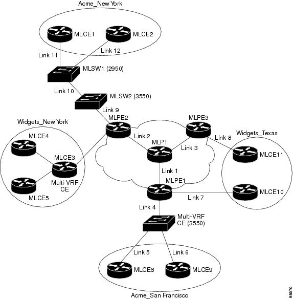
Figure 6-2 shows the topology for the network used to define the service requests in this section.
PE-CE Example
In the PE-CE example, the service provider needs to create an MPLS service for a CE (mlce1) in their customer site Acme_NY (in New York).
Multi-VRF Example
In the Multi-VRF example, the service provider needs to create an MPLS service between a CE (mlce4) in their customer site Widgets_NY (in New York) and a Multi-VRFCE (mlce3) located in their customer site Widgets_NY (in New York).
The goal is to create a single service request that defines a link between the customer site in New York and the PE (mlpe2).
PE-Only Example
In the PE-Only example, the service provider needs to create an MPLS service for a PE (mlpe2.)
Figure 6-2 Example Network Topology
Creating a PE-CE Service Request
To create a PE-CE service request, follow these steps:
Step 1
a.
b.
c.
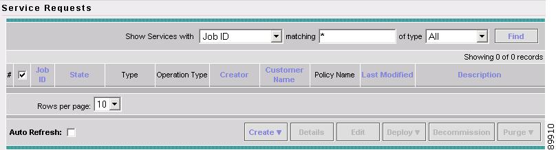
The Service Requests dialog box appears (see Figure 6-3).
Figure 6-3 Initial Service Requests Dialog Box
Step 2
A drop-down list is displayed, showing the types of service requests you can create.
Step 3
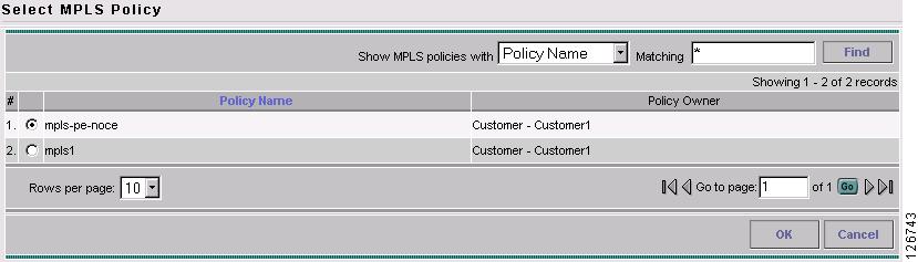
The Select MPLS Policy dialog box appears (see Figure 6-4).
This dialog box displays the list of all the MPLS service policies that have been defined in ISC.
Figure 6-4 Selecting the MPLS Policy for This Service
Step 4
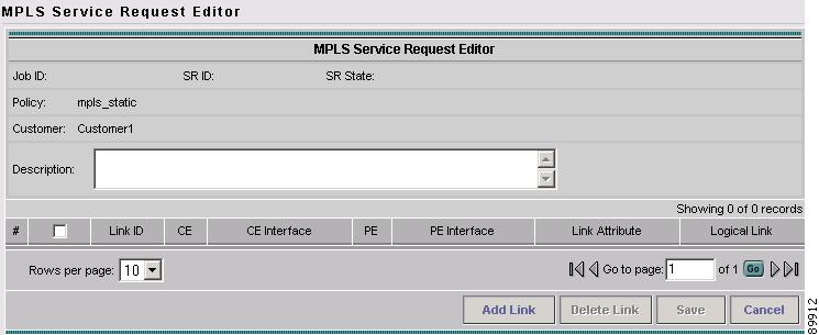
The MPLS Service Request Editor appears (see Figure 6-5).
Figure 6-5 MPLS Service Request Editor
Step 5
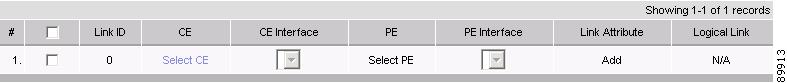
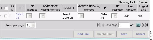
The MPLS Service Request Editor now displays a set of fields, as shown in Figure 6-6. Notice that the Select CE field is enabled. Specifying the CE for the link is the first task required to define the link for this service.
Figure 6-6 Initial Fields Displayed to Define PE-CE Link
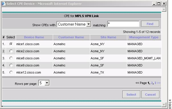
Step 6
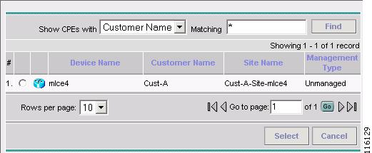
The Select CPE Device dialog box is displayed (see Figure 6-7).
Figure 6-7 Selecting the CE for the MPLS Link
a.
b.
c.
d.
To go to the another page of CE devices, click the number of the page you want to go to.
Step 7
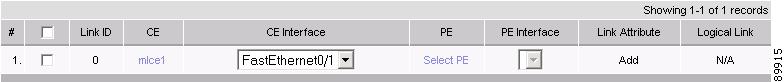
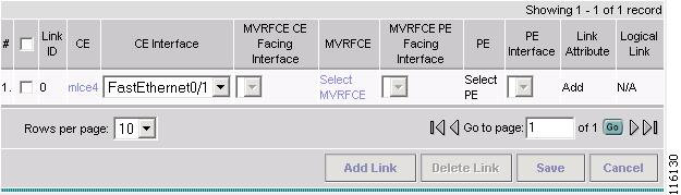
You return to the Service Request Editor window, where the name of the selected CE is now displayed in the CE column.
Step 8
Figure 6-8 CE and CE Interface Fields Defined
Note that in the PE column, the Select PE option is now enabled.
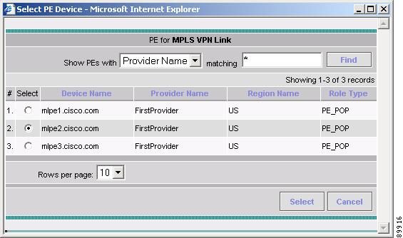
Step 9
The Select PE Device dialog box is displayed (see Figure 6-9).
Figure 6-9 Selecting the PE for the MPLS Link
a.
b.
c.
d.
To go to the another page of PE devices, click the number of the page you want to go to.
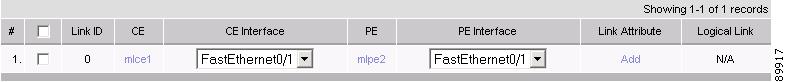
Step 10
You return to the Service Request Editor window, where the name of the selected PE is now displayed in the PE column.
Step 11
Figure 6-10 PE and PE Interface Fields Defined
Note that the Link Attribute Add option is now enabled.
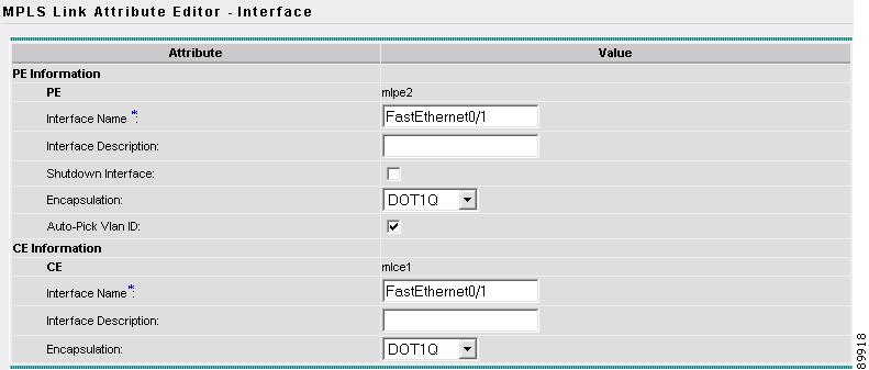
Step 12
The MPLS Link Attribute Editor appears, showing the fields for the interface parameters (see Figure 6-11).
Figure 6-11 Specifying the MPLS Link Interface Attributes
The field values displayed in this dialog box reflect the values specified in the service policy associated with this service. For details on each of the PE and CE interface fields, see Specifying PE and CE Interface Parameters.
Note
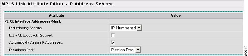
Step 13
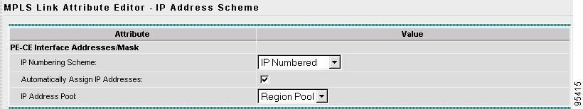
The MPLS Link Attribute Editor for the IP Address Scheme appears (see Figure 6-12).
Figure 6-12 Specifying the MPLS Link IP Address Attributes
The field values displayed in this dialog box reflect the values specified in the service policy associated with this service. For details on the IP address scheme fields, see Specifying IP Address Scheme.
Step 14
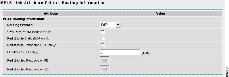
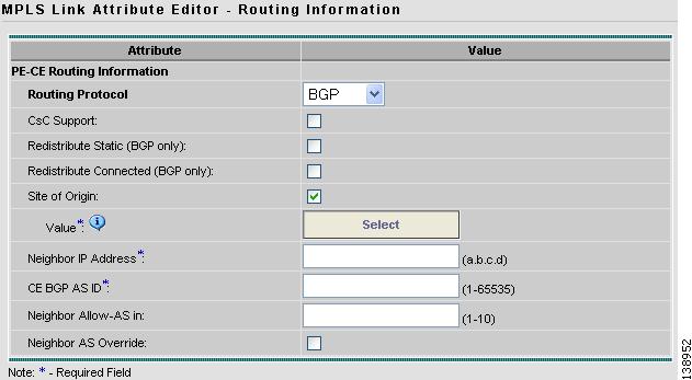
The MPLS Link Attribute Editor for Routing Information appears (see Figure 6-13).
Figure 6-13 Specifying the MPLS Link Routing Protocol Attributes
The field values displayed in this dialog box reflect the values specified in the service policy associated with this service. For details on the routing information for the PE and CE, see Specifying Routing Protocol for a Service.
Because the service policy used for this service specified the routing protocol as editable, you can change the routing protocol for this service request as needed.
Note
Step 15
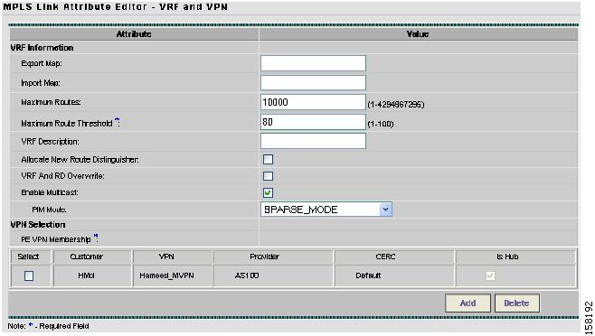
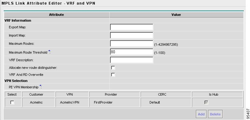
The MPLS Link Attribute Editor for the VRF and VPN attributes appears (see Figure 6-14).
Figure 6-14 Specifying the MPLS Link VRF and VPN Attributes
The field values displayed in this dialog box reflect the values specified in the service policy associated with this service. For details on the VRF and VPN information, see Defining the Service Policy VRF and VPN Information.
Step 16
SPARSE_MODE
SPARCE_DENSE_MODE
Tip
Step 17
You return to the MPLS Service Request Editor. You can define multiple links in this service request.
Step 18
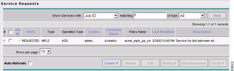
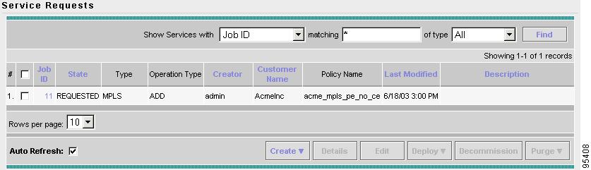
You return to the Service Requests dialog box, where the information for the link you just defined is now displayed (see Figure 6-15).
Figure 6-15 Service Request for an MPLS Link Completed
As you can see, the service request is in the Requested state. When all the links for this service have been defined, you must deploy the service, as described in Deploying Service Requests.
IP Multicast VPN Service Request Configlets
Step 1
The Service Request Details window appears for the associated job number.
Step 2
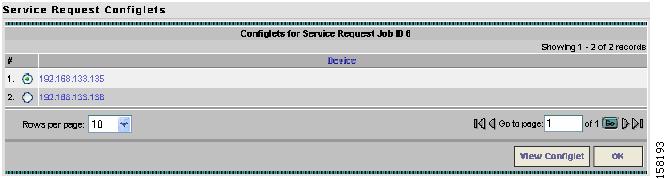
The Service Request Configlets window appears (see Figure 6-16).
Figure 6-16 Service Request Configlets
Step 3
Examples of PE and CE configlets are shown below:
PE Configlet
--------------------------------------------------Configlet #1, Job ID 8 (Created: 2006-05-31 17:39:01)!ip vrf V2:Hameed_MVPNrd 100:1011route-target import 100:12route-target import 100:13route-target export 100:12maximum routes 10000 80mdt default 239.232.1.1mdt data 239.232.2.0 0.0.0.255 threshold 50mdt mtu 1500!interface Ethernet1/1.99description Ethernet1/1.99 dot1q vlan id=99. By VPNSC: Job Id# = 8encapsulation dot1Q 99ip vrf forwarding V2:Hameed_MVPNip address 10.99.0.1 255.255.255.252ip pim sparse-modeno shutdown!ip multicast vrf V2:Hameed_MVPN route-limit 100000!ip multicast-routing vrf V2:Hameed_MVPN!ip pim vrf V2:Hameed_MVPN autorp listener!ip pim vrf V2:Hameed_MVPN ssm range ssmList!ip pim vrf V2:Hameed_MVPN rp-address 10.99.1.2 rp12List!ip pim vrf V2:Hameed_MVPN rp-address 10.99.1.5 override!ip pim vrf V2:Hameed_MVPN rp-address 10.99.1.1 rp11List override!router ospf 21 vrf V2:Hameed_MVPNredistribute bgp 100 subnetsnetwork 10.99.0.0 0.0.0.3 area 21!router bgp 100address-family ipv4 vrf V2:Hameed_MVPNredistribute ospf 21 vrf V2:Hameed_MVPN match internal external 1 external 2exit-address-family--------------------------------------------------CE Configlet
--------------------------------------------------Configlet #1, Job ID 8 (Created: 2006-05-31 17:39:01)!interface Ethernet0/0.99description Ethernet0/0.99 dot1q vlan id=99. By VPNSC: Job Id# = 8encapsulation dot1Q 99ip vrf forwarding V2:Hameed_MVPNip address 10.99.0.2 255.255.255.252ip pim sparse-modeno shutdown!router ospf 21network 10.99.0.0 0.0.0.3 area 21--------------------------------------------------
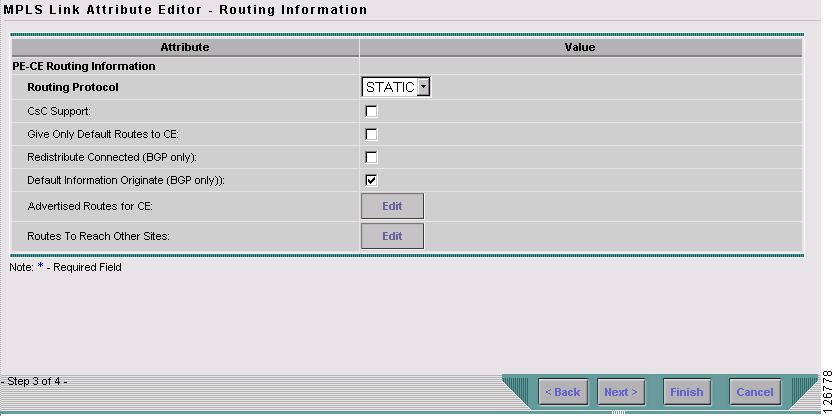
Static Routing Protocols
For the static routing protocol, in addition to the attributes that you can specify in the service policy, here are two additional attributes that you can add via the Link Attribute Editor.
•
•
Step 1
Figure 6-17 Static Routing Protocol
You can edit Advertised Routes for CE: and Routes to Reach other Sites: for this service request.
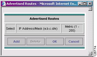
Step 2
Figure 6-18 Advertised Routes Window
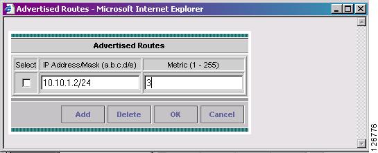
Step 3
Figure 6-19 Add IP Address
Step 4
Step 5
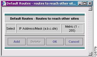
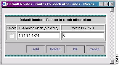
Figure 6-20 Routes to reach other sites Window
Step 6
Figure 6-21 Add an IP Address
Step 7
Creating a Multi-VRF Service Request
This chapter contains graphics for the following sections:
•
•
Multi-VRF Overview
MPLS-VPNs provide security and privacy as traffic travels through the provider network. The CE router has no mechanism to guarantee private networks across the traditional LAN network. Traditionally to provide privacy, either a switch needed to be deployed and each client be placed in a separate VLAN or a separate CE router is needed per each client's organization or IP address grouping attaching to a PE.
These solutions are costly to the customer as additional equipment is needed and requires more network management and provisioning of each client site.
Multi-VRF is a new feature, introduced in Cisco IOS release 12.2(4)T, that addresses these issues. Multi-VRF extends limited PE functionality to a CE router in an MPLS-VPN model. A CE router now has the ability to maintain separate VRF tables in order to extend the privacy and security of an MPLS-VPN down to a branch office rather than just at the PE router node.
CE routers use VRF interfaces to form a VLAN-like configuration on the customer side. Each VRF on the CE router is mapped to a VRF on the PE router. With Multi-VRF, the CE router can only configure VRF interfaces and support VRF routing tables. Multi-VRF extends some of the PE functionality to the CE router—there is no label exchange, there is no LDP adjacency, there is no labeled packet flow between PE and CE. The only PE-like functionality that is supported is the ability to have multiple VRFs on the CE router so that different routing decisions can be made. The packets are sent toward the PE as IP packets.
Creating an Multi-VRFCE PE-CE Service Request
To create a MVRFCE PE-CE Service Request, follow these steps:
Step 1
Step 2
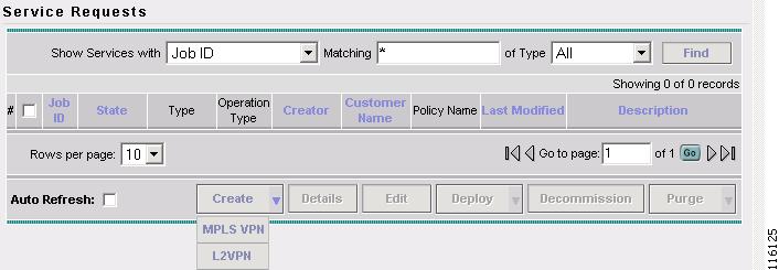
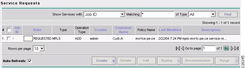
The Service Requests window appears, as shown in Figure 6-22.
Figure 6-22 Service Requests
Step 3
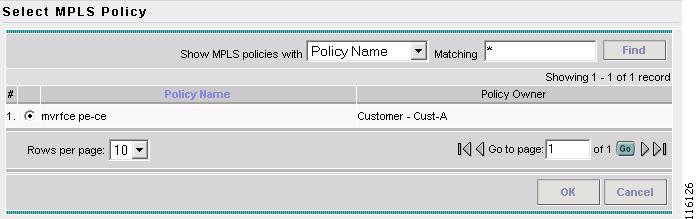
The Select MPLS Policy window appears, as shown in Figure 6-23.
Figure 6-23 Select MPLS Policy
Step 4
Step 5
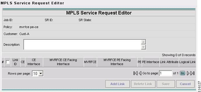
The MPLS Service Request Editor window appears, as shown in Figure 6-24.
Figure 6-24 MPLS Service Request Editor
Step 6
The MPLS Service Request Editor window appears, as shown in Figure 6-25.
Figure 6-25 MPLS Service Request Editor - Select CE
Step 7
The Select CPE Device - CE window appears, as shown in Figure 6-26.
Figure 6-26 Select CPE Device - CE
Step 8
The MPLS Service Request Editor window appears, as shown in Figure 6-27.
Figure 6-27 MPLS Service Request Editor - CE Interface
Step 9
Step 10
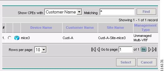
The Select CPE Device - MVRFCE window appears, as shown in Figure 6-28.
Figure 6-28 Select CPE Device - MVRFCE
Step 11
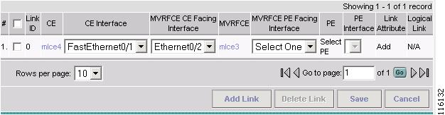
The MPLS Service Request Editor window appears, as shown in Figure 6-29.
Figure 6-29 MPLS Service Request Editor - MVRFCE CE Facing Interface
Step 12
Step 13
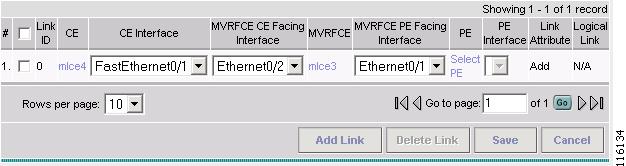
The MPLS Service Request Editor window appears, as shown in Figure 6-30.
Figure 6-30 MPLS Service Request Editor - Choose MVRFCE PE Facing Interface
Step 14
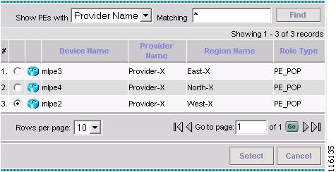
The Select PE Device window appears, as shown in Figure 6-31.
Figure 6-31 Choose PE Device
Step 15
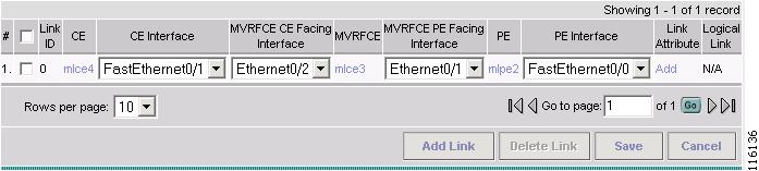
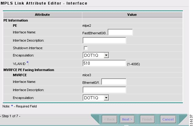
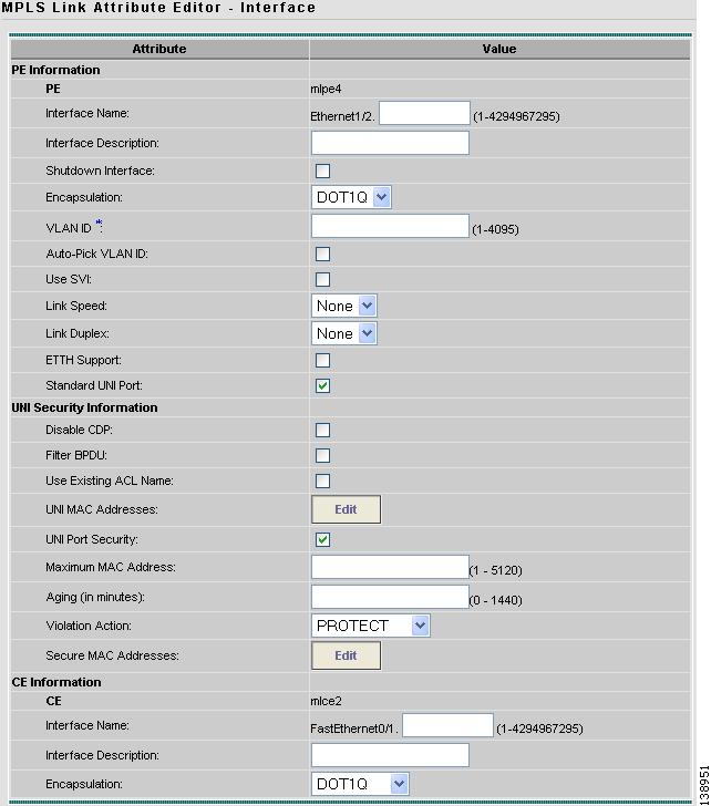
The MPLS Link Attribute Editor window appears, as shown in Figure 6-32.
Figure 6-32 MPLS Link Attribute Editor - Interface
Step 16
Step 17
The MPLS Link Attribute Editor - Interface window appears, as shown in Figure 6-32.
Figure 6-33 MPLS Link Attribute Editor - Interface
Step 18
Step 19
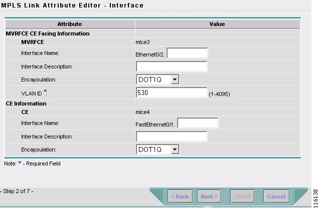
The MPLS Link Attribute Editor - Interface window appears, as shown in Figure 6-34.
Figure 6-34 MPLS Link Attribute Editor - Interface
Step 20
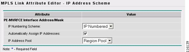
Click Next.
The MPLS Link Attribute Editor - IP Address Scheme window appears, as shown in Figure 6-35.
Figure 6-35 MPLS Link Attribute Editor - IP Address Scheme
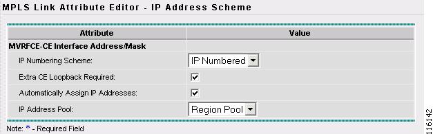
Step 21
The MPLS Link Attribute Editor - IP Address Scheme window appears, as shown in Figure 6-36.
Figure 6-36 MPLS Link Attribute Editor - IP Address Scheme
Step 22
The MPLS Link Attribute Editor - Routing Information window reappears, as shown in Figure 6-37.
Figure 6-37 MPLS Link Attribute Editor - PE Routing Information
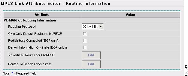
Step 23
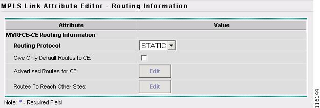
The MPLS Link Attribute Editor - Routing Information window reappears, as shown in Figure 6-38.
Figure 6-38 MPLS Link Attribute Editor - MVRFCE Routing Information
Step 24
The MPLS Link Attribute Editor - VRF and VPN window appears (not shown).
Step 25
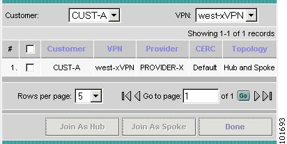
The Choose VPN window appears, as shown in Figure 6-39.
Figure 6-39 Choose VPN
Step 26
Step 27
Step 28
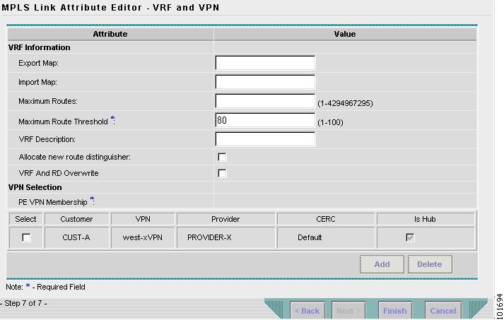
The MPLS Link Attribute Editor - VRF and VPN window reappears, as shown in Figure 6-40.
Figure 6-40 MPLS Service Request Editor
Step 29
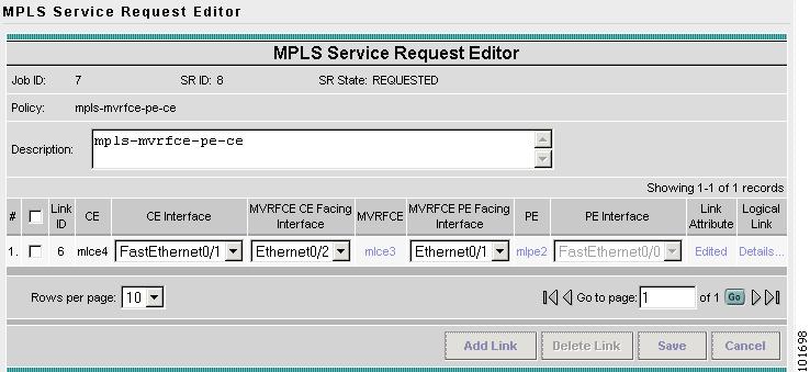
The MPLS Service Request Editor window appears, as shown in Figure 6-41.
Figure 6-41 MPLS Service Request Editor
Step 30
The MPLS Service Requests window appears, as shown in Figure 6-42.
Figure 6-42 Service Request
The MPLS VPN MVRFCE PE-CE Service Request is in the Requested state and ready to deploy.
Creating a PE-Only Service Request
To create a PE-Only (No CE) service request, follow these steps:
Step 1
a.
b.
c.
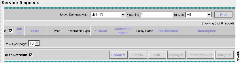
The Service Requests dialog box appears (see Figure 6-43).
Figure 6-43 Initial Service Requests Dialog Box
Step 2
A drop-down list is displayed, showing the types of service requests you can create.
Step 3
The Select MPLS Policy dialog box appears (see Figure 6-44).
This dialog box displays the list of all the MPLS service policies that have been defined in ISC.
Figure 6-44 Selecting the PE-Only Policy for this Service
Step 4
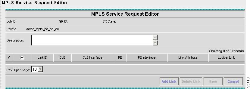
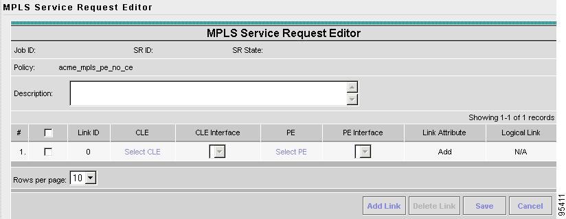
The MPLS Service Request Editor appears (see Figure 6-45).
Figure 6-45 MPLS Service Request Editor
Step 5
The MPLS Service Request Editor now displays a set of fields, as shown in Figure 6-46. Notice that the Select PE field is enabled. Specifying the PE for the link is the first task required to define the link for this service, unless a CLE switch link is needed. If a CLE switch is needed go to "Adding a CLE Service Request" section.
Figure 6-46 Initial Fields Displayed to Define PE-Only Link
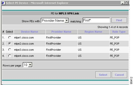
Step 6
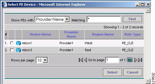
The Select PE Device dialog box is displayed (see Figure 6-47).
Figure 6-47 Selecting the PE for the PE-Only Link
a.
b.
c.
d.
To go to the another page of PE devices, click the number of the page you want to go to.
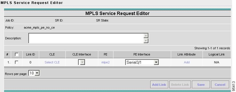
Step 7
You return to the Service Request Editor window, where the name of the selected PE is now displayed in the PE column.
PE Interface: Choose the PE interface from the drop-down list (see Figure 6-48).
Figure 6-48 PE and PE Interface Fields Defined
Note that the Link Attribute Add option is now enabled.
Step 8
The MPLS Link Attribute Editor is displayed, showing the fields for the interface parameters (see Figure 6-49).
Figure 6-49 Specifying the PE-Only Link Interface Attributes
The field values displayed in this dialog box reflect the values specified in the service policy associated with this service. For details on the PE interface fields, see Specifying PE and CE Interface Parameters.
Step 9
The MPLS Link Attribute Editor for the IP Address Scheme appears (see Figure 6-50).
Figure 6-50 Specifying the PE-Only Link IP Address Attributes
The field values displayed in this dialog box reflect the values specified in the service policy associated with this service. For details on the IP address scheme fields, see Specifying IP Address Scheme.
Step 10
The MPLS Link Attribute Editor for Routing Information appears (see Figure 6-51).
Figure 6-51 Specifying the PE-Only Routing Protocol Attributes
The field values displayed in this dialog box reflect the values specified in the service policy associated with this service. For details on the routing information for the PE, see Specifying Routing Protocol for a Service.
Because the service policy used for this service specified the routing protocol as editable, you can change the routing protocol for this service request as needed.
Step 11
a.
The Site for SOO Value window appears.
b.
Step 12
The MPLS Link Attribute Editor for the VRF and VPN attributes appears (see Figure 6-52).
Figure 6-52 Specifying the PE-Only Link VRF and VPN Attributes
The field values displayed in this dialog box reflect the values specified in the service policy associated with this service. For details on the VRF and VPN information, see Defining the Service Policy VRF and VPN Information.
Step 13
You return to the MPLS Service Request Editor. You can define multiple links in this service request.
Step 14
You return to the Service Requests dialog box, where the information for the link you just defined is now displayed (see Figure 6-53).
Figure 6-53 Service Request for an PE-Only Link Completed
You can add additional links to this service request by choosing Add Link and specifying the attributes of the next link in the service. As you can see, the service request is in the Requested state. When all the links for this service have been defined, you must deploy the service, as described in Deploying Service Requests.
Adding a CLE Service Request
To add a CLE link:
Step 1
Step 2
The Select PE Device dialog box is displayed (see Figure 6-54).
Figure 6-54 Selecting the CLE for the PE-Only Link
a.
b.
c.
d.
To go to the another page of PE devices, click the number of the page you want to go to.
Step 3
You return to the Service Request Editor window, where the name of the selected CLE is now displayed in the CLE column.
Step 4
Step 5
Deploying Service Requests
When you have queued one or more service requests, you can then deploy them. This procedure automatically audits the new service requests. This audit passes the service request into an operational state.
ISC sets up a scheduled task that deploys service requests to the appropriate routers. This involves computing the configlets for each service request, downloading the configlets to the routers, and running audit reports to determine whether the service was successfully deployed.
You can choose to deploy the service requests immediately or schedule their deployment.
Step 1
a.
b.
c.
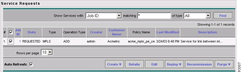
The Service Requests dialog box appears (see Figure 6-55).
Figure 6-55 Selecting a Service Requests to Deploy
Step 2
Step 3
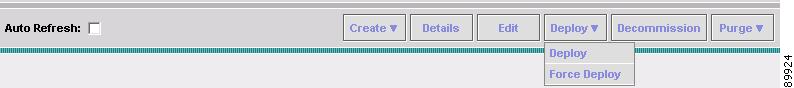
You have two deployment options, as shown in Figure 6-56:
•
•
Figure 6-56 Deployment Options
Step 4
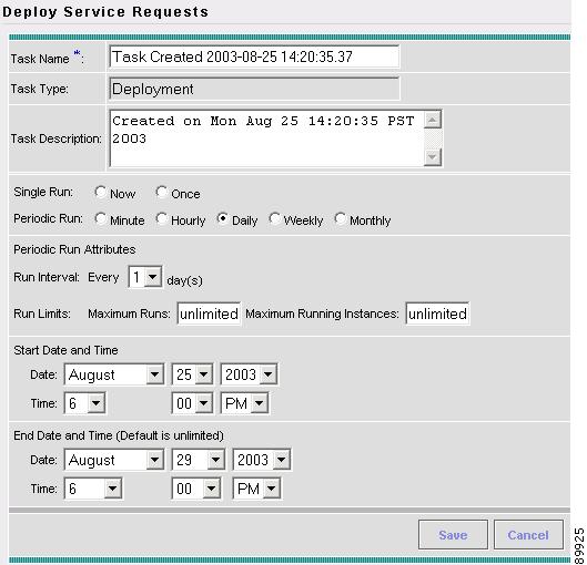
The Deploy Service Requests dialog box appears, which allows you to schedule when you want to deploy the selected service request (see Figure 6-57).
Figure 6-57 Scheduling a Service Request for Deployment
Step 5
Step 6
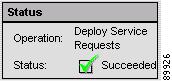
You return to the Service Requests dialog box. Check the Status display in the lower left corner of the window. If the service request has been deployed successfully, the Status display appears as shown in Figure 6-58.
Figure 6-58 Status for Successful Deployment
Step 7
You can view logs to check on the task status and whether or not it completed successfully. To view logs, choose Monitoring > Task Manager > Logs (for Log details, refer to Cisco IP Solution Center Infrastructure Reference on Cisco.com).
Monitoring Service Requests
Once you have created and deployed a service request, you can monitor its status.
Step 1
Step 2
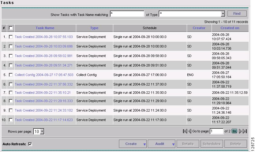
The Task Manager dialog box is displayed (see Figure 6-59).
Figure 6-59 Viewing Information on Running Tasks
Step 3
Step 4
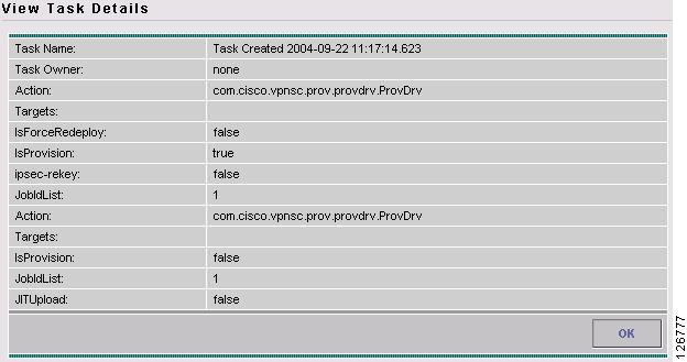
The Service Request Details window appears (see Figure 6-60).
Figure 6-60 Service Request Details Displayed
Auditing Service Requests
This section describes auditing in MPLS VPN. It contains the following sections:
Functional Audit
A functional audit verifies that the links in a service request or VPN are working correctly. The audit checks the routes to remote CEs in the VRF route tables on the PE devices. The user can optionally ping the connected CE from the PE to verify that the link is functional.
How to Perform a Functional Audit
ISC automatically provides a functional audit whenever a service request is deployed or force-redeployed.
You can also create a task to do a functional audit for one or more service requests. To create a task to do a functional audit, follow these steps:
Step 1
Step 2
a.
b.
c.
d.
e.
f.
Where to Find the Functional Audit
To find the Functional Audit, follow these steps:
Step 1
On the service request details page, the Audit button has two choices:
•
•
Step 2
Why a Functional Audit Could Fail
A Functional Audit could fail for the following reasons:
•
•
•
A Ping could fail for the following reasons:
•
•
Configuration Audit
A configuration audit verifies if all the commands for a service (service intent) are present on the network elements that participate in the service.
How to Perform a Configuration Audit
ISC automatically does a config audit whenever a service request is deployed or force-redeployed. You can also create a task to do a configuration audit for one or more service requests.
To create a task to do a configuration audit, follow these steps:
Step 1
Step 2
Step 3
Where to Find the Configuration Audit
After selecting the service request, click on Details.
On the details page, the Audit button has two choices:
•
•
Click on Config to display the Configuration audit report.
Why a Configuration Audit Could Fail
A configuration audit can fail if some of the commands are removed after provisioning from the network elements. This could happen if the commands are manually removed or they are removed as part of provisioning some other service.
Editing Configuration Files
To view or edit an existing router configuration file:
Caution
Step 1
The Inventory and Connection Manager window is displayed.
Step 2
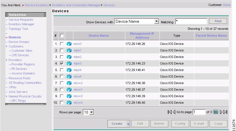
The Devices dialog box appears (see Figure 6-61).
Figure 6-61 List of Devices Recognized by ISC
Step 3
Step 4
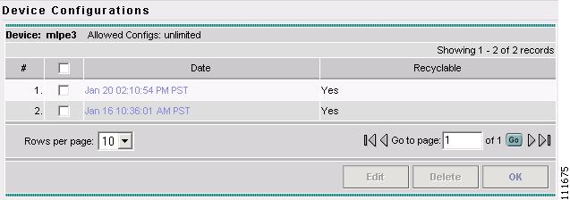
The Device Configurations dialog box appears (see Figure 6-62).
Figure 6-62 List of Configurations for the Selected Device
The Device Configurations dialog box displays the list of the current versions of the configuration files for the selected device. The configurations are listed by date and time. The configuration file listed first is the latest version.
Step 5
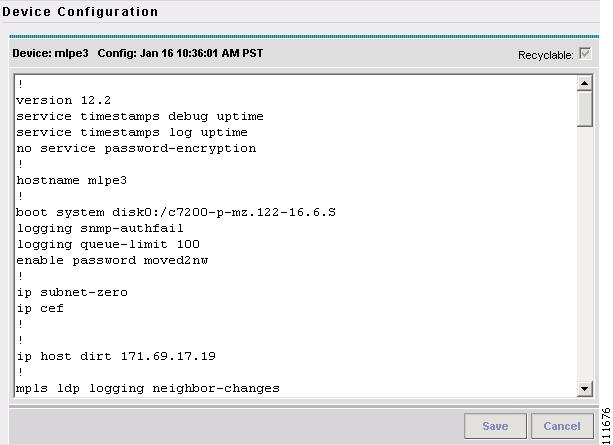
The contents of the selected configuration file are displayed (see Figure 6-63).
Figure 6-63 Selected Configuration Displayed
You can view or edit the displayed device configuration file.
Step 6
Step 7