-
Cisco IP Solution Center MPLS VPN User Guide, 4.1
-
Index
-
Preface
-
Getting Started
-
Provisioning Unmanaged Multi-VRF CE
-
Creating Resource Pools
-
Defining VPNs and CERCs
-
MPLS VPN Service Policies
-
MPLS VPN Service Requests
-
Provisioning Regular PE-CE Links
-
Provisioning MVRFCE PE-CE Links
-
Provisioning Management VPN
-
Provisioning Cable Services
-
Provisioning Carrier Supporting Carrier
-
Provisioning Multiple Devices
-
Spanning Multiple Autonomous Systems
-
Creating Custom MPLS Reports
-
IP Solution Center - MPLS VPN
-
Service Request Transition States
-
Troubleshooting MPLS VPN
-
 Feedback
Table Of Contents
Overview of the ISC Management Network
Unmanaged Customer Edge Routers
Issues Regarding Access to VPNs
Provisioning a Management CE in ISC
Creating an MCE Service Request
Adding PE-CE Links to the Management VPN
Provisioning Management VPN
This chapter describes how to implement the IP Solutions Center (ISC) Management VPN. This chapter contains the following major sections:
•
Overview of the ISC Management Network
•
Overview of the ISC Management Network
This section provides the fundamental concepts and considerations for administering customer edge routers (CEs) in the context of an ISC management subnet. Before ISC can be appropriately deployed to deliver services to customers, the question of whether the CEs are to be managed by the Service Provider or not must be answered
This section contains the following sections:
•
•
Unmanaged Customer Edge Routers
One of the options available to the Service Provider is to not manage the customer edge routers (CEs) connected to the Service Provider network. For the Service Provider, the primary advantage of an unmanaged CE is administrative simplicity.
If the CEs are unmanaged, the provider can use IPv4 connectivity for all management traffic. ISC is not employed for provisioning or managing unmanaged CEs.
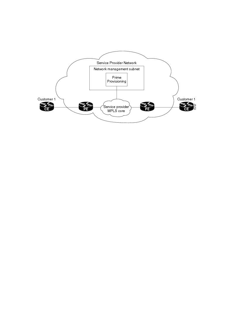
Figure 9-1 shows a basic topology with unmanaged CEs. The network management subnet has a direct link to the Service Provider MPLS core network.
Figure 9-1 Service Provider Network and Unmanaged CEs
Regarding unmanaged CEs, Service Providers should note the following considerations:
•
•
–
–
–
–
–
–
•
•
–
–
•
•
•
Managed Customer Edge Routers
The alternative to unmanaged CEs is managed CEs, that is, customer edge routers managed by the Service Provider. Managed CEs can be wholly within the Service Provider's administrative domain or co-managed between the provider and the customer, although CE co-management poses a number of ongoing administrative challenges and is not recommended.
Regarding managed CEs, Service Providers should note the following considerations:
•
•
–
–
–
–
•
•
•
•
•
•
•
•
•
The following sections discuss the concepts and issues required for administering a managed CE environment.
Network Management Subnets
The Network Management Subnet is required when the provider's service offering entails the management of CEs. Once a CE is in a VPN, it is no longer accessible by means of conventional IPv4 routing unless one of the techniques described in this chapter is employed.
Figure 9-2 shows the ISC network management subnet and the devices that might be required to connect to it:
Figure 9-2 The ISC Network Management Subnet
Issues Regarding Access to VPNs
The core issues with regard to gaining access to VPNs are as follows:
•
•
•
•
ISC does not handle any of these responsibilities—doing so must be designed and implemented by the Service Provider.
•
Before you provision a CE in the ISC, you might be able to reach the CE via IPv4 connectivity, but the moment the product deploys a service request, you cannot reach that CE any more—unless you have first implemented the network management subnet.
Implementation Techniques
The network management subnet must have access to a Management CE (MCE) and PEs.
The network management subnet is appropriate—and necessary—when there is an intent to have managed CEs connected via an in-band connection. In-band indicates a single link or permanent virtual circuit (PVC) that carries both the customer's VPN traffic, as well as the provider's network management traffic.
Management CE (MCE)
The network management subnet is connected to the Management CE (MCE). The MCE emulates the role of a customer edge router (CE), but the MCE is in provider space and serves as a network operations center gateway router. The MCE is part of a management site as defined in the ISC.
You configure the MCE by identifying the CE as part of the management LAN in ISC.
Management PE (MPE)
The Management PE (MPE) emulates the role of a PE in the provider core network. The MPE connects the MCE to the provider core network. An MPE can have a dual role as both a PE and the MPE.
The MPE needs access to the following devices:
At the current time, ISC recommends two main network management subnet implementation techniques:
•
The MPE-MCE link uses a Management VPN (see Management VPN) to connect to managed CEs. To connect to the PEs, the MPE-MCE link uses a parallel IPv4 link.
•
In the Out-of-Band technique, the MCE has IPv4 connectivity (that is, not MPLS VPN connectivity) to all the CEs and PEs in the network (see Out-of-Band Technique). In this context, out-of-band signifies a separate link between PEs that carries the provider's management traffic.
The network management subnet technique the provider chooses to implement depends on many factors, which are discussed later in this chapter.
Management VPN
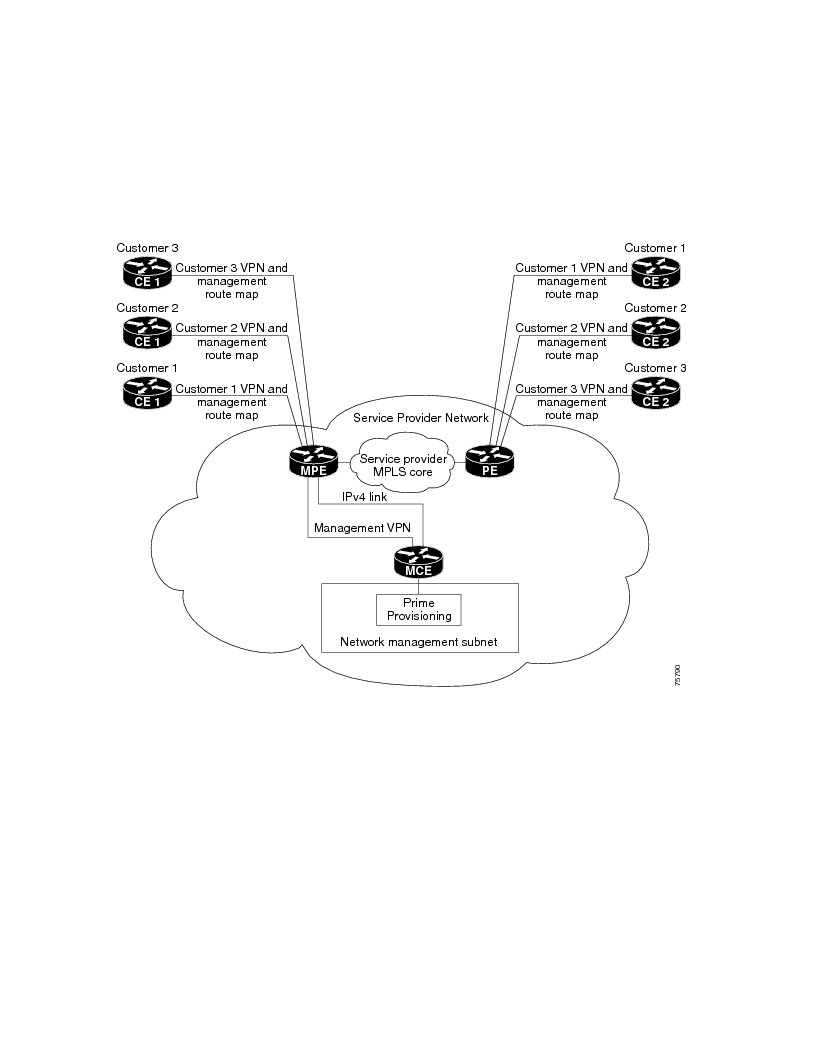
The Management VPN technique is the default method provisioned by ISC. A key concept for this implementation technique is that all the CEs in the network are a member of the management VPN. To connect to the PEs, the MPE-MCE link uses a parallel IPv4 link. Figure 9-3 shows a typical topology for the Management VPN technique.
Figure 9-3 Typical Topology for a Management VPN Network
When employing the Management VPN technique, the MPE-MCE link uses a management VPN to connect to managed CEs. To connect to the PEs, the MPE-MCE link employs a parallel IPv4 link.
Each CE in a customer VPN is also added to the management VPN by selecting the Join the management VPN option in the service request user interface.
The function of the management route map is to allow only the routes to the specific CE into the management VPN. The Cisco IOS supports only one export route map and one import route map per VRF.
As shown in Figure 9-3, a second parallel non-MPLS VPN link is required between the MPE and MCE to reach the PEs.
Note
Advantages
The advantages involved in implementing the Management VPN technique are as follows:
•
•
•
Out-of-Band Technique
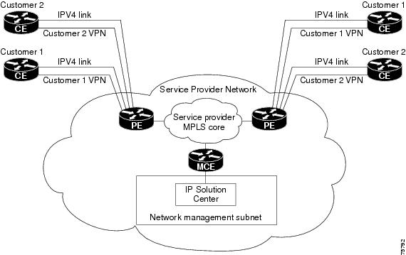
The Out-of-Band technique does not employ a management VPN to manage the CEs. Out-of-band connectivity is provided by IPv4 links. Out-of-band signifies a separate link between PEs that carries the provider's management traffic. As shown in Figure 9-4, the MCE provides separation between the provider's routes and the customer's routes.
Figure 9-4 Out-of-Band Technique
The Out-of-Band technique has the advantage of being relatively simple to set up, and no management VPN is required. However, its disadvantages are that it is expensive since it requires an IPv4 connection to each CE. Also, due to the delicate staging requirements for this technique, the Out-of-Band implementation does have a high degree of complexity.
Provisioning a Management CE in ISC
The ISC network management subnet is connected to the Management CE (MCE). The MCE emulates the role of a customer edge router (CE), but the MCE is in provider space and serves as a network operations center gateway router. The MCE is part of a management site as defined in ISC.
This section contains the following sections:
•
Defining a CE as an MCE
You configure the MCE by identifying the CE as part of the management LAN in ISC software. To define a CE as an MCE, follow these steps:
Step 1
Step 2
Step 3
Step 4
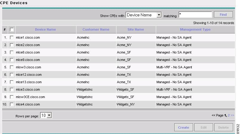
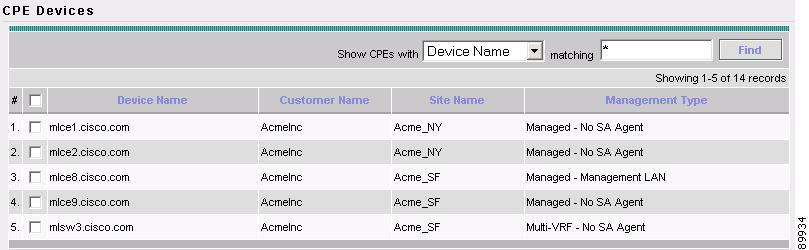
The list of CPE devices for all currently defined customers is displayed (see Figure 9-5).
Figure 9-5 List of All CPEs for All Customers
Step 5
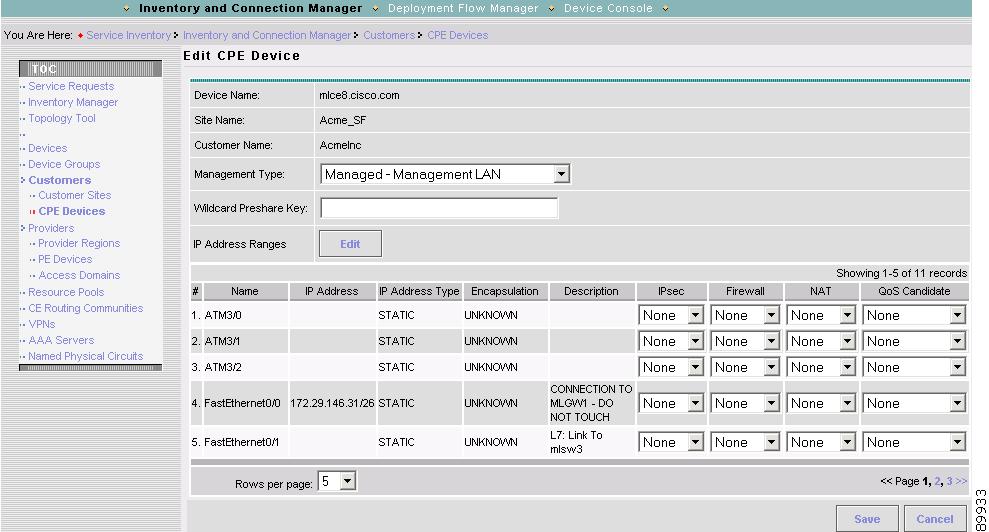
The Edit CPE Device dialog box appears, displaying the pertinent information for the selected CPE (see Figure 9-6).
Figure 9-6 Editing the Selected CPE Device
Step 6
Step 7
You return to the list of CPE devices, where the new management type for the selected CE (in our example, 3. mlce8.cisco.com) is now displayed (see Figure 9-7).
Figure 9-7 Selected CE Defined as a Management CE
Creating an MCE Service Request
To create an MCE service request, follow these steps:
Step 1
a.
b.
c.
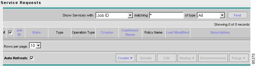
The Service Requests dialog box appears (see Figure 9-8).
Figure 9-8 Initial Service Requests Dialog Box
Step 2
A drop-down list is displayed, showing the types of service requests you can create.
Step 3
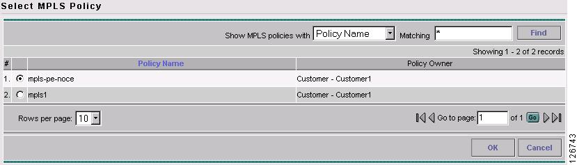
The Select MPLS Policy dialog box appears (see Figure 9-9).
This dialog box displays the list of all the MPLS service policies that have been defined in ISC.
Figure 9-9 Selecting the MPLS Policy for This Service
Step 4
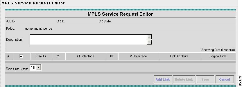
The MPLS Service Request Editor appears (see Figure 9-10).
Figure 9-10 MPLS Service Request Editor
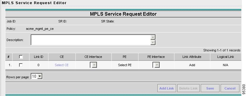
Step 5
The MPLS Service Request Editor now displays a set of fields, as shown in Figure 9-11. Notice that the Select CE field is enabled. Specifying the CE for the link is the first task required to define the link for this service.
Figure 9-11 Initial Fields Displayed to Define PE-CE Link
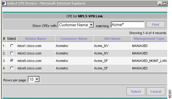
Step 6
The Select CPE Device dialog box is displayed (see Figure 9-12).
Figure 9-12 Selecting the MCE for the MPLS Link
a.
b.
c.
d.
To go to the another page of CE devices, click the number of the page you want to go to.
Step 7
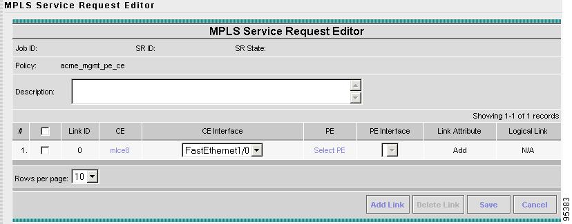
You return to the Service Request Editor window, where the name of the selected CE is now displayed in the CE column.
Step 8
Figure 9-13 CE and CE Interface Fields Defined
Note that in the PE column, the Select PE option is now enabled.
Step 9
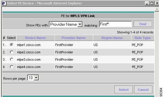
The Select PE Device dialog box is displayed (see Figure 9-14).
Figure 9-14 Selecting the PE for the MPLS Link
Step 10
You return to the Service Request Editor window, where the name of the selected PE is now displayed in the PE column.
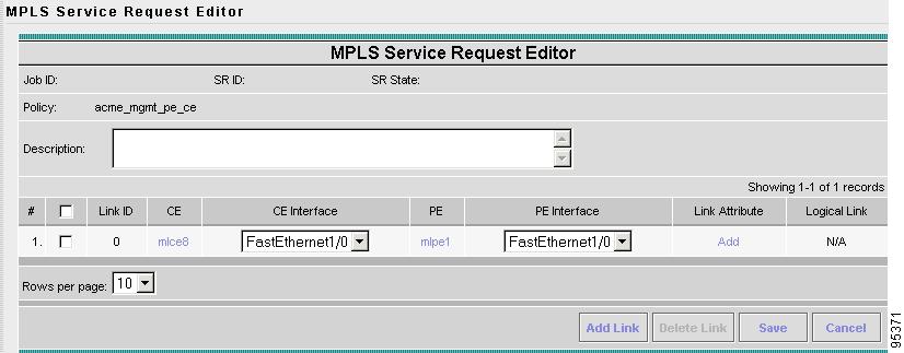
Step 11
Figure 9-15 PE and PE Interface Fields Defined
Note that the Link Attribute Add option is now enabled.
Step 12
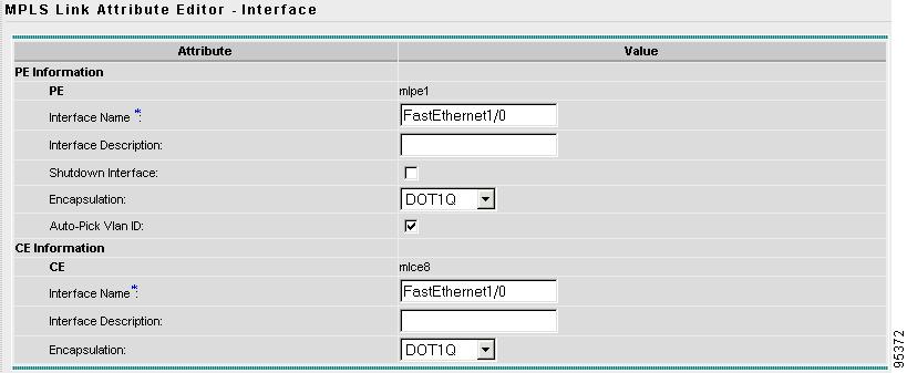
The MPLS Link Attribute Editor is displayed, showing the fields for the interface parameters (see Figure 9-16).
Figure 9-16 Specifying the MPLS Link Interface Attributes
The field values displayed in this dialog box reflect the values specified in the service policy associated with this service. For details on each of the PE and CE interface fields, see Specifying PE and CE Interface Parameters.
Note
Step 13
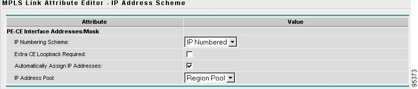
The MPLS Link Attribute Editor for the IP Address Scheme appears (see Figure 9-17).
Figure 9-17 Specifying the MPLS Link IP Address Attributes
The field values displayed in this dialog box reflect the values specified in the service policy associated with this service. For details on the IP address scheme fields, see Specifying IP Address Scheme.
Step 14
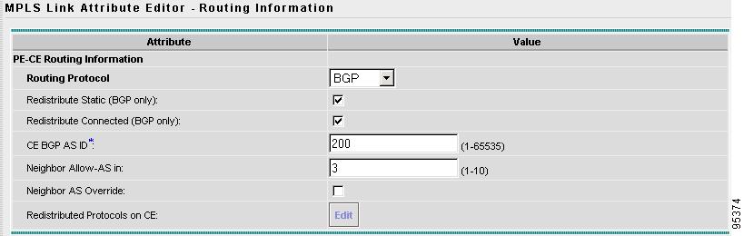
The MPLS Link Attribute Editor for Routing Information appears (see Figure 9-18).
Figure 9-18 Specifying the MPLS Link Routing Protocol Attributes
The field values displayed in this dialog box reflect the values specified in the service policy associated with this service. For details on the routing information for the PE and CE, see Specifying Routing Protocol for a Service.
Because the service policy used for this service specified the routing protocol as editable, you can change the routing protocol for this service request as needed.
Step 15
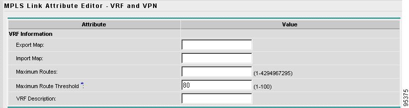
The MPLS Link Attribute Editor for the VRF and VPN attributes appears (see Figure 9-19).
Figure 9-19 Specifying the MPLS Link VRF and VPN Attributes
The field values displayed in this dialog box reflect the values specified in the service policy associated with this service. For details on the VRF and VPN information, see Defining the Service Policy VRF and VPN Information.
Step 16
You return to the MPLS Service Request Editor.
Step 17
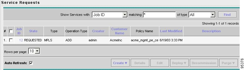
You return to the Service Requests dialog box, where the information for the link you just defined is now displayed (see Figure 9-20).
Figure 9-20 Service Request for an MPLS Link Completed
You can add additional links to this service request by choosing Add Link and specifying the attributes of the next link in the service. As you can see, the service request is in the Requested state. When all the links for this service have been defined, you must deploy the service.
Adding PE-CE Links to the Management VPN
When you have created the Management VPN, then you can proceed to add service for the PE-CE links you want to participate in the Management VPN.
To add PE-CE links, follow these steps:
Step 1
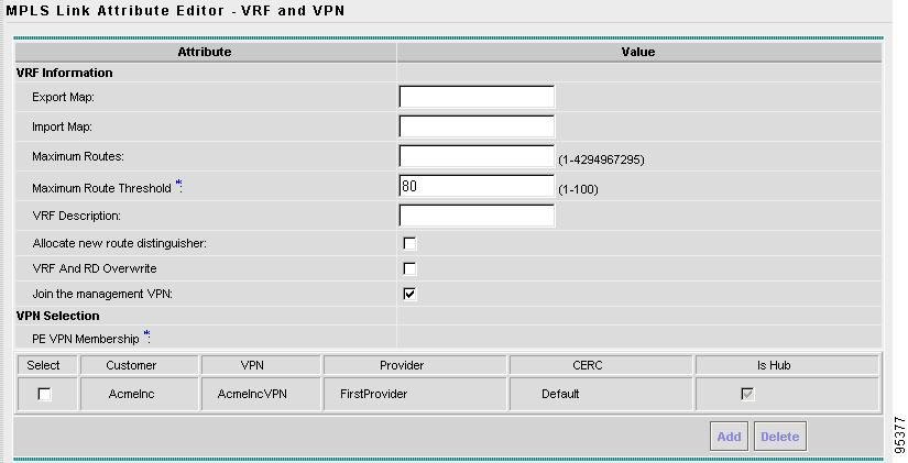
Step 2
Figure 9-21 Joining a CE to the Management VPN
When you join the CE with the Management VPN in this step, ISC generates the appropriate route-map statements in the PE configlet.
The function of the management route map is to allow only the routes to the specific CE into the management VPN. Cisco IOS supports only one export route map and one import route map per VRF (and therefore, per VPN).
Step 3