-
Cisco IP Solution Center MPLS VPN User Guide, 4.1
-
Index
-
Preface
-
Getting Started
-
Provisioning Unmanaged Multi-VRF CE
-
Creating Resource Pools
-
Defining VPNs and CERCs
-
MPLS VPN Service Policies
-
MPLS VPN Service Requests
-
Provisioning Regular PE-CE Links
-
Provisioning MVRFCE PE-CE Links
-
Provisioning Management VPN
-
Provisioning Cable Services
-
Provisioning Carrier Supporting Carrier
-
Provisioning Multiple Devices
-
Spanning Multiple Autonomous Systems
-
Creating Custom MPLS Reports
-
IP Solution Center - MPLS VPN
-
Service Request Transition States
-
Troubleshooting MPLS VPN
-
 Feedback
Table Of Contents
Creating CE Routing Communities
Defining VPNs and CERCs
During service deployment, ISC generates the Cisco IOS commands to configure the logical VPN relationships.
At the beginning of the provisioning process, before creating a Service Policy, a VPN must be defined within ISC. The first element in a VPN definition is the name of the VPN.
This chapter describes how to define MPLS VPNs, IP Multicast VPNs, and CE Routing Communities (CERCs).
This chapter contain the following major sections:
•
Creating CE Routing Communities
Creating MPLS VPN
Step 1
Step 2
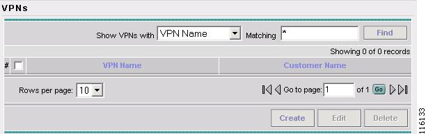
The VPN window appears, as shown in Figure 4-1.
Figure 4-1 VPNs
Step 3
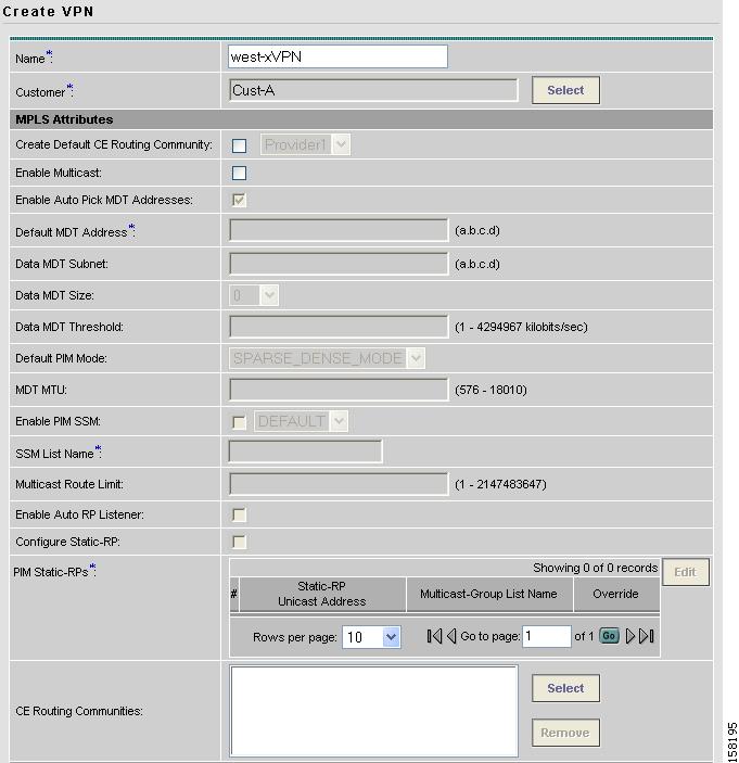
The Create VPN window appears, as shown in Figure 4-2.
Figure 4-2 Create VPN
Step 4
Step 5
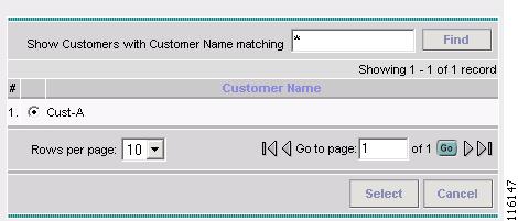
The Choose Customer window appears, as shown in Figure 4-3.
Figure 4-3 Choose Customer
Step 6
The VPNs window reappears.
Step 7
•
•
Note
Step 8
The VPN Name (west-xVPN) is associated with the Customer (Cust-A) in this new VPN definition.
Creating IP Multicast VPN
Step 1
Step 2
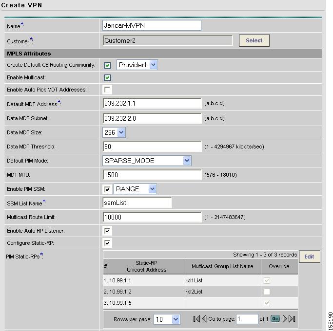
The current window will refresh with additional fields becoming active (see Figure 4-4).
Figure 4-4 Creating Multicast VPN
Step 3
Default MDT Address
Data MDT Subnet
Step 4
Step 5
Step 6
SPARSE_MODE
SPARSE_DENSE_MODE
Tip
Step 7
Step 8
When you check the check box:
a.
b.
Step 9
Step 10
Step 11
Step 12
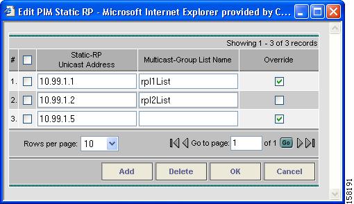
When you check this, the Edit option for PIM Static-RPs goes active.
Step 13
The Edit PIM Static RPs window appears, see Figure 4-5).
Figure 4-5 Edit PIM Static RPs
Step 14
These data now appear in the main Create VPN window (see Figure 4-4).
Step 15
Creating CE Routing Communities
When you create a VPN, the ISC software creates one default CE routing community (CERC) for you. But if your network topology and configuration require customized CERC definitions, you can define CERCs customized for your network.
Tip
To build complex topologies, it is necessary to break down the required connectivity between CEs into groups, where each group is either fully meshed, or has a hub-and-spoke pattern. A CE can be in more than one group at a time, so long as each group has one of the two basic configuration patterns.
Each subgroup in the VPN needs its own CERC. Any CE that is only in one group just joins the corresponding CERC (as a spoke if necessary). If a CE is in more than one group, then you can use the Advanced Setup choice during provisioning to add the CE to all the relevant groups in one service request. Given this information, ISC does the rest, assigning route target values and VRF tables to arrange the precise connectivity the customer requires.
To define a new CERC:
Step 1
Step 2
The Inventory and Connection Manager window appears.
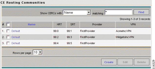
Step 3
The CE Routing Communities dialog box appears (see Figure 4-6).
Figure 4-6 CE Routing Communities Defined for This VPN
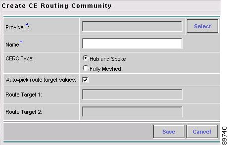
Step 4
The Create CE Routing Community dialog box appears (see Figure 4-7).
Figure 4-7 Defining a New CE Routing Community
Step 5
c.
The Choose Provider dialog box appears.
d.
e.
f.
g.
By default, the Auto-pick route target values check box is checked. If you uncheck the check box, you can enter the Route Target values manually.
Caution
Step 6