-
Cisco IP Solution Center MPLS VPN User Guide, 4.1
-
Index
-
Preface
-
Getting Started
-
Provisioning Unmanaged Multi-VRF CE
-
Creating Resource Pools
-
Defining VPNs and CERCs
-
MPLS VPN Service Policies
-
MPLS VPN Service Requests
-
Provisioning Regular PE-CE Links
-
Provisioning MVRFCE PE-CE Links
-
Provisioning Management VPN
-
Provisioning Cable Services
-
Provisioning Carrier Supporting Carrier
-
Provisioning Multiple Devices
-
Spanning Multiple Autonomous Systems
-
Creating Custom MPLS Reports
-
IP Solution Center - MPLS VPN
-
Service Request Transition States
-
Troubleshooting MPLS VPN
-
 Feedback
Table Of Contents
Provisioning Regular PE-CE Links
Defining a VPN for the PE-CE Link
Creating MPLS VPN PE-CE Service Policies
Creating a PE-CE Service Policy
Creating a PE-NoCE Service Policy
Creating MPLS VPN PE-CE Service Requests
Creating a PE-CE Service Request
Creating a PE-NoCE Service Request
Provisioning Regular PE-CE Links
This chapter describes how to configure MPLS VPN PE-CE links in the IP Solution Center (ISC) provisioning process. This chapter contains the following major sections:
•
Creating MPLS VPN PE-CE Service Policies
•
MPLS VPN PE-CE Link Overview
This section contains the following sections:
To provision an MPLS VPN service in ISC, you must first create an MPLS VPN Service Policy. In ISC, a Service Policy is a set of default configurations for creating and deploying a Service Request.
ISC supports two MPLS VPN Service Policy Types: Regular PE-CE and MVRFCE PE-CE. The following scenarios focus on the Regular PE-CE Policy Type.
The Regular PE-CE Policy Type is a normal PE to CE link between two devices. This Policy Type has two options:
•
•
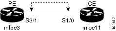
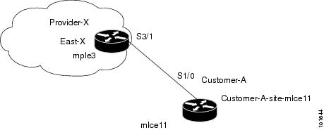
Figure 7-1 shows an example of a normal PE to CE link between two devices.
Figure 7-1 PE to CE link with CE Present
In a PE to CE link with CE Present enabled, interfaces S3/1 and S1/0 are configured as an MPLS VPN link in the Service Request process.
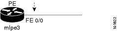
Figure 7-2 shows an example of a PE Only link with no CE.
Figure 7-2 PE to CE link with No CE
In a PE to CE link with CE Present disabled, interface FE0/0 is configured as an MPLS VPN link in the Service Request process.
Network Topology
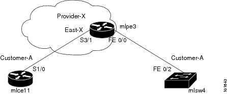
Figure 7-3 shows an overview of the network topology in which the MPLS VPN PE-CE links are created.
Figure 7-3 Network Topology for MPLS VPN PE-CE Scenarios.
The network topology in Figure 7-3 illustrates the lab environment of a service provider (Provider-X) and one customer (Cust-A). There is one Region (East-X) and one PE (mlpe3.cisco.com). Each customer device (one CE and one CLE) represents a Site (mlce11-Site and mlsw4-Site).
Prerequisite Tasks
Before you can create a Service Policy in ISC, you must complete the following Inventory Management tasks:
Step 1
Step 2
Step 3
Step 4
Step 5
Step 6
Step 7
Infrastructure Data
In the subsequent PE-CE scenarios, the following infrastructure data is used:
•
•
•
•
•
•
•
•
•
•
–
–
–
–
–
•
–
–
–
•
–
–
–
•
–
–
Defining a VPN for the PE-CE Link
During service deployment, ISC generates the Cisco IOS commands to configure the logical VPN relationships.
At the beginning of the provisioning process, before creating a Service Policy, a VPN must be defined within ISC. The first element in a VPN definition is the name of the VPN.
To create a VPN Name, follow these steps:
Step 1
Step 2
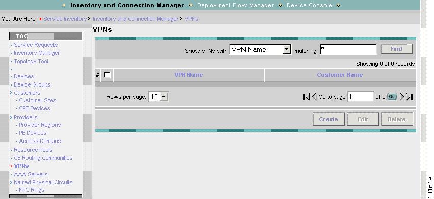
The VPN window appears, as shown in Figure 7-4.
Figure 7-4 VPNs
Step 3
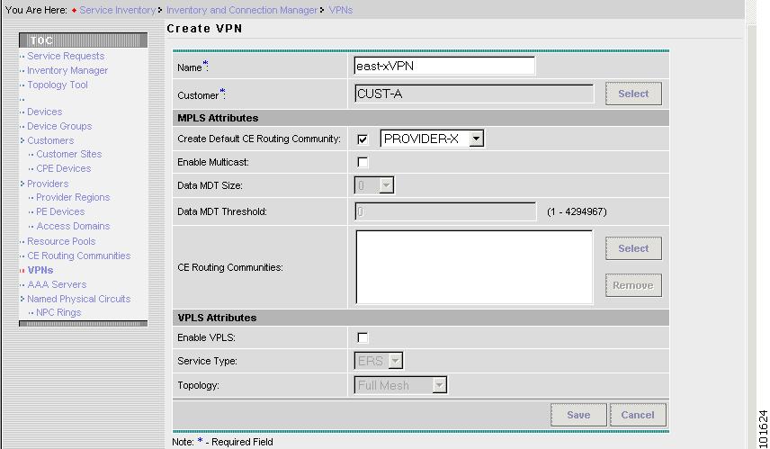
The Create VPN window appears, as shown in Figure 7-5.
Figure 7-5 Create VPN
Step 4
•
•
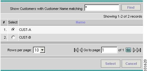
The Select Customer window appears, as shown in Figure 7-6.
Figure 7-6 Choose Customer
Step 5
Step 6
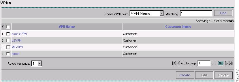
The VPNs window reappears, as shown in Figure 7-7.
Figure 7-7 VPNs
The VPN Name (east-xVPN) is associated with the Customer (Cust-A) in this new VPN definition.
Creating MPLS VPN PE-CE Service Policies
This section contains the following sections:
•
•
•
PE-CE Service Policy Overview
Figure 7-8 shows an example of the PE-CE link that is defined in the PE-CE Service Policy scenario.
Figure 7-8 PE-CE Topology
Creating a PE-CE Service Policy
To create a PE-CE Service Policy, follow these steps:
Step 1
Step 2
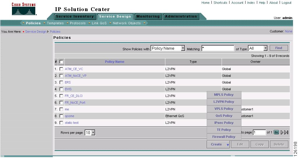
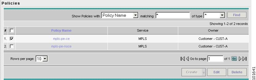
The Policies window appears, as shown in Figure 7-9.
Figure 7-9 Policies
Step 3
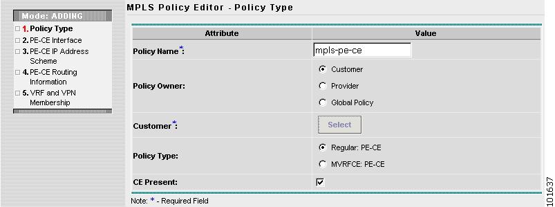
The MPLS Policy Editor - Policy Type window appears, as shown in Figure 7-10.
Figure 7-10 MPLS Policy Editor - Policy Type
Step 4
•
•
•
•
•
Step 5
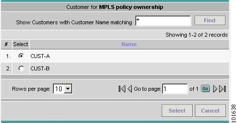
The Customer for MPLS Policy ownership window appears, as shown in Figure 7-11.
Figure 7-11 Customer for MPLS Policy
Step 6
Step 7
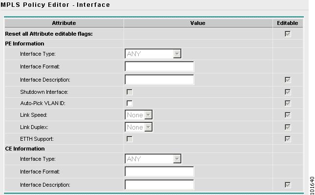
The MPLS Policy Editor - Interface window appears, as shown in Figure 7-12.
Figure 7-12 The MPLS Policy Editor - Interface
Step 8
Note
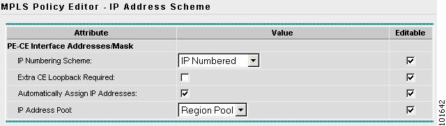
The MPLS Policy Editor - IP Address Scheme window appears, as shown in Figure 7-13.
Figure 7-13 The MPLS Policy Editor - IP Address Scheme
Step 9
•
•
•
Step 10
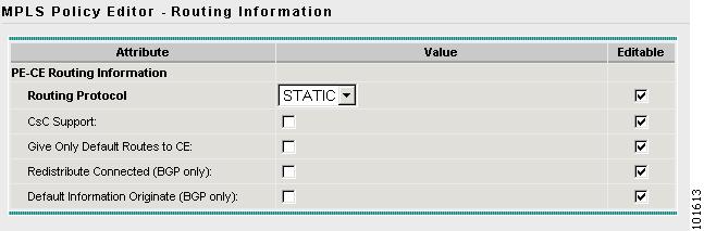
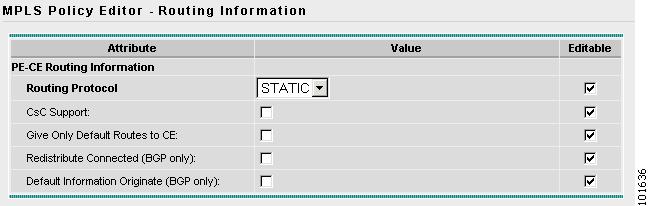
The MPLS Policy Editor - Routing Information window appears, as shown in Figure 7-14.
Figure 7-14 The MPLS Policy Editor - Routing Information
Step 11
Note
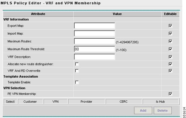
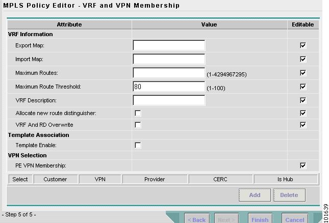
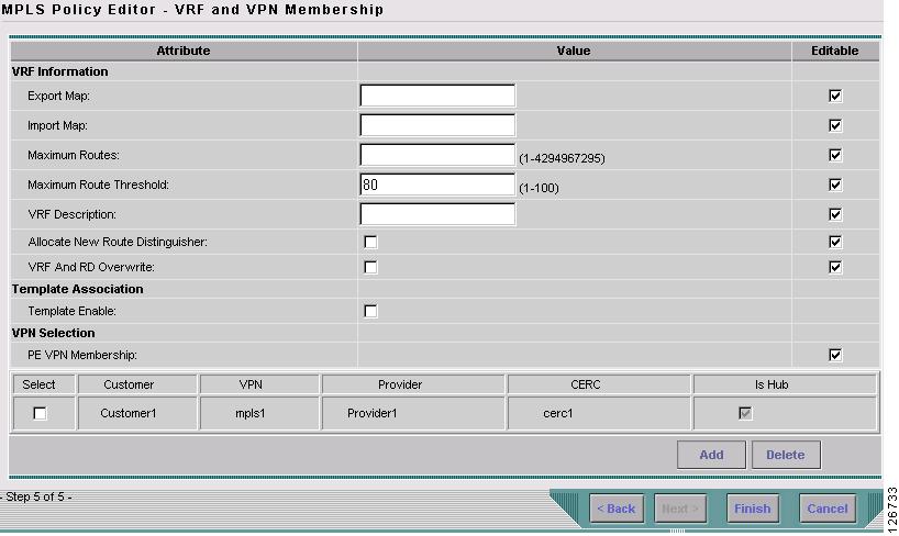
The MPLS Policy Editor - VRF and VPN Membership window appears, as shown in Figure 7-15.
Figure 7-15 The MPLS Policy Editor - VRF and VPN Membership
Step 12
Note
Step 13
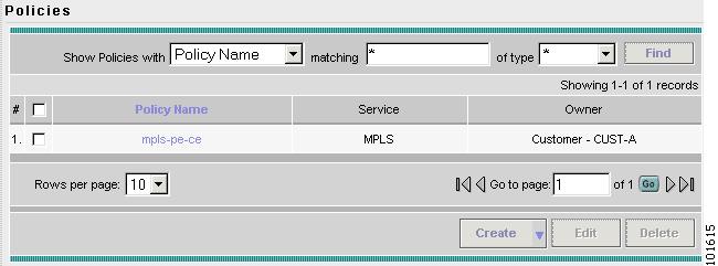
The Policies window reappears, as shown in Figure 7-16.
Figure 7-16 Policies
The MPLS VPN PE-CE Service Policy is complete.
Creating a PE-NoCE Service Policy
To create a PE-NoCE Service Policy, follow these steps:
Step 1
Step 2
The Policies window appears, as shown in Figure 7-17.
Figure 7-17 Policies
Step 3
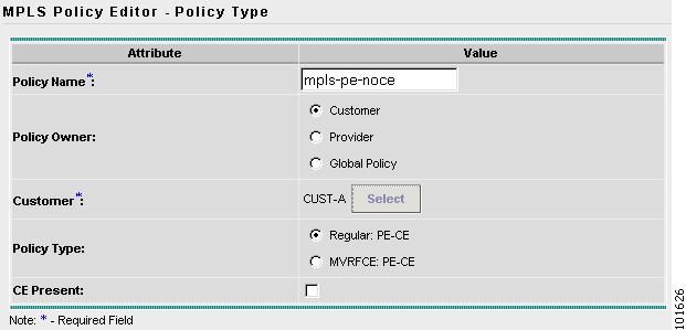
The MPLS Policy Editor - Policy Type window appears, as shown in Figure 7-18.
Figure 7-18 MPLS Policy Editor - Policy Type
Step 4
•
•
•
•
•
Step 5
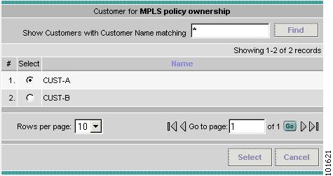
The Customer for MPLS Policy window appears, as shown in Figure 7-19.
Figure 7-19 Customer for MPLS Policy
Step 6
Step 7
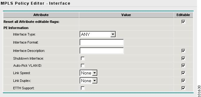
The MPLS Policy Editor - Interface window appears, as shown in Figure 7-20.
Figure 7-20 The MPLS Policy Editor - Interface
Step 8
Note
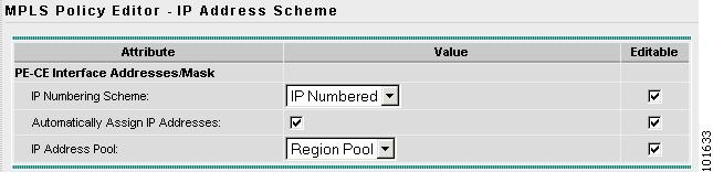
The MPLS Policy Editor - IP Address Scheme window appears, as shown in Figure 7-21.
Figure 7-21 The MPLS Policy Editor - IP Address Scheme
Step 9
•
•
•
•
Step 10
The MPLS Policy Editor - Routing Information window appears, as shown in Figure 7-22.
Figure 7-22 The MPLS Policy Editor - Routing Information
Step 11
Note
The MPLS Policy Editor - VRF and VPN Membership window appears, as shown in Figure 7-23.
Figure 7-23 The MPLS Policy Editor - VRF and VPN Membership
Step 12
The Policies window reappears, as shown in Figure 7-24.
Figure 7-24 Policies
The MPLS VPN PE-NoCE Service Policy is complete.
Creating MPLS VPN PE-CE Service Requests
This section contains the following sections:
•
•
Creating a PE-CE Service Request
To create a PE-CE Service Request, follow these steps:
Step 1
Step 2
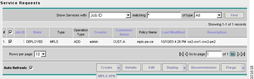
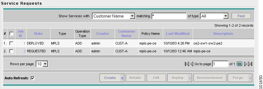
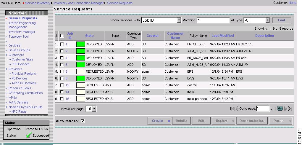
The Service Requests window appears, as shown in Figure 7-25.
Figure 7-25 Service Requests
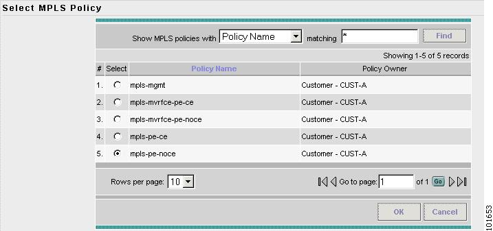
Step 3
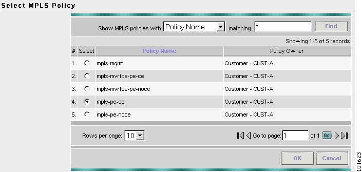
The Select MPLS Policy window appears, as shown in Figure 7-26.
Figure 7-26 Choose MPLS Policy
Step 4
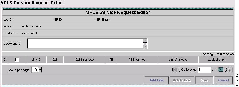
Step 5
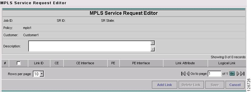
The MPLS Service Request Editor window appears, as shown in Figure 7-27.
Figure 7-27 MPLS Service Request Editor
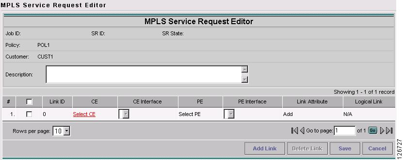
Step 6
The MPLS Service Request Editor window appears, as shown in Figure 7-28.
Figure 7-28 MPLS Service Request Editor - Select CE
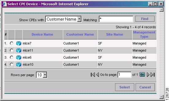
Step 7
The CPE for MPLS VPN Link window appears, as shown in Figure 7-29.
Figure 7-29 CPE for MPLS VPN Link
Step 8
The MPLS Service Request Editor window appears.
Step 9
The MPLS Service Request Editor window appears.
Step 10
The PE for MPLS VPN Link window appears, as shown in Figure 7-30.
Figure 7-30 PE for MPLS VPN Link
Step 11
The MPLS Service Request Editor window appears.
Step 12
The MPLS Service Request Editor window appears.
Step 13
The PE for MPLS VPN Link window appears, as shown in Figure 7-31.
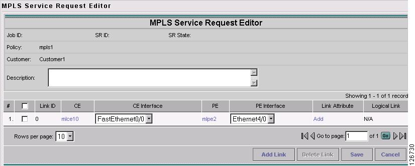
Figure 7-31 MPLS Service Request Editor
Step 14
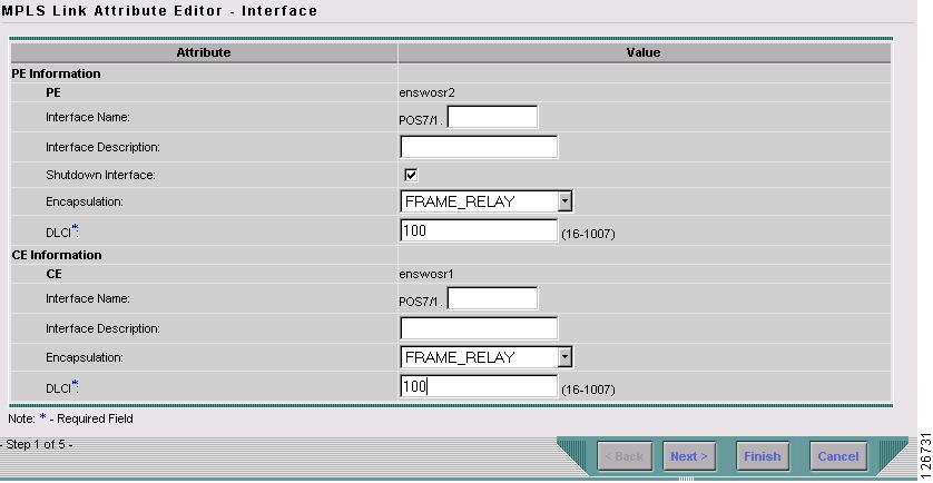
The MPLS Link Attribute Editor - Interface window appears, as shown in Figure 7-32.
Figure 7-32 MPLS Link Attribute Editor - Interface
PE Information
Step 15
Step 16
CE Information
Step 17
Step 18
Step 19
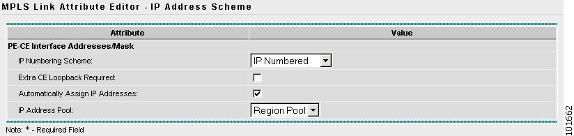
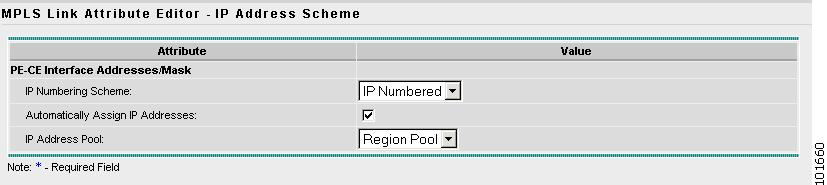
The MPLS Link Attribute Editor - IP Address Scheme window appears, as shown in Figure 7-33.
Figure 7-33 MPLS Link Attribute Editor - IP Address Scheme
Step 20
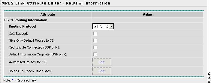
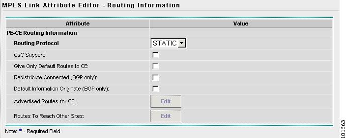
The MPLS Link Attribute Editor - Routing Information window reappears, as shown in Figure 7-34.
Figure 7-34 MPLS Link Attribute Editor - Routing Information
Step 21
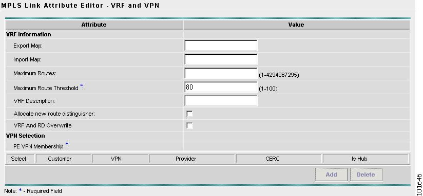
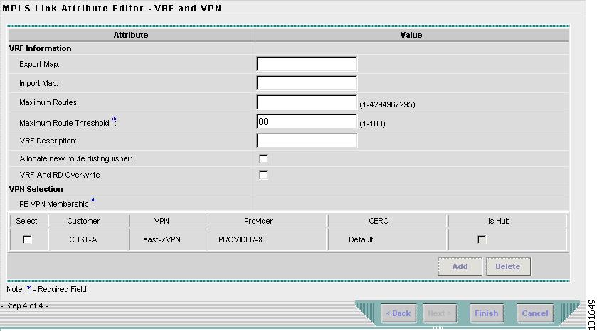
The MPLS Link Attribute Editor - VRF and VPN window appears, as shown in Figure 7-35.
Figure 7-35 MPLS Link Attribute Editor - VRF and VPN
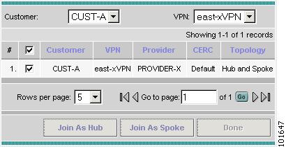
Step 22
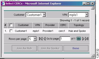
Figure 7-36 Select CERCs Window
Step 23
Step 24
Step 25
Step 26
Step 27
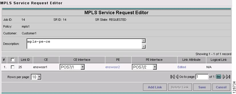
Figure 7-37 MPLS Service Request Editor
Step 28
The MPLS Service Request Editor window reappears, as shown in Figure 7-38.
Figure 7-38 MPLS Service Request Editor
Step 29
The MPLS Service Requests window reappears, as shown in Figure 7-39.
Figure 7-39 Service Request
The MPLS VPN PE-CE Service Request is in the Requested state and ready to deploy.
Creating a PE-NoCE Service Request
To create a PE-NoCE Service Request, follow these steps:
Step 1
Step 2
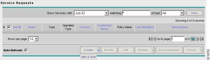
The Service Requests window appears, as shown in Figure 7-40.
Figure 7-40 Service Requests
Step 3
The Select MPLS Policy window appears, as shown in Figure 7-41.
Figure 7-41 Select MPLS Policy
Step 4
Step 5
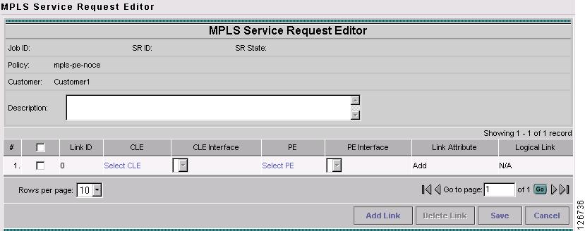
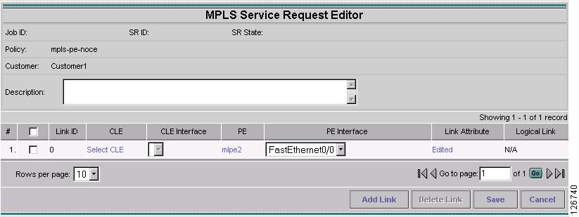
The MPLS Service Request Editor window appears, as shown in Figure 7-42.
Figure 7-42 MPLS Service Request Editor
Step 6
The MPLS Service Request Editor window appears, as shown in Figure 7-43.
Figure 7-43 MPLS Service Request Editor - Select CE
Step 7
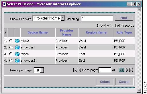
The PE for MPLS VPN Link window appears, as shown in Figure 7-44.
Figure 7-44 PE for MPLS VPN Link
Step 8
The MPLS Service Request Editor window appears.
Step 9
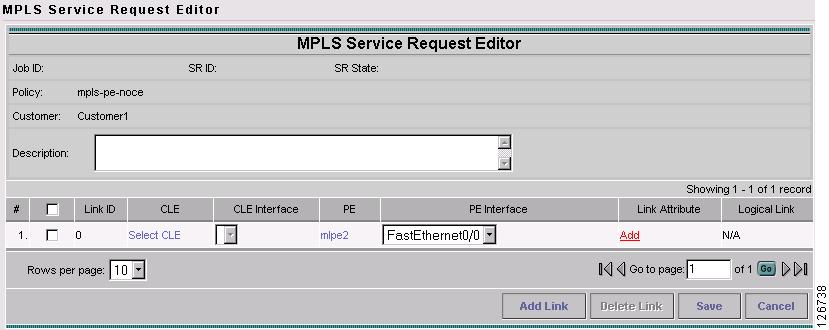
The MPLS Service Request Editor window appears, as shown in Figure 7-45.
Figure 7-45 MPLS Service Request Editor
Step 10
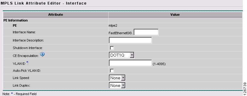
The MPLS Link Attribute Editor - Interface window appears, as shown in Figure 7-46.
Figure 7-46 MPLS Link Attribute Editor - Interface
Step 11
Note
Step 12
The MPLS Link Attribute Editor - IP Address Scheme window appears, as shown in Figure 7-47.
Figure 7-47 MPLS Link Attribute Editor - IP Address Scheme
Step 13
The MPLS Link Attribute Editor - Routing Information window reappears, as shown in Figure 7-48.
Figure 7-48 MPLS Link Attribute Editor - Routing Information
Step 14
The MPLS Link Attribute Editor - VRF and VPN window reappears, as shown in Figure 7-49.
Figure 7-49 MPLS Link Attribute Editor - VRF and VPN
Click Add to join the VPN.
The Join VPN dialog box appears, as shown in Figure 7-50.
Figure 7-50 MPLS Service Request Editor
Step 15
Step 16
Click Done.
The MPLS Service Request Editor window reappears, as shown in Figure 7-51.
Figure 7-51 MPLS Service Request Editor
Step 17
The MPLS Service Requests Editor window reappears, as shown in Figure 7-52.
Figure 7-52 MPLS Service Request Editor
Step 18
The MPLS Service Requests window reappears, as shown in Figure 7-53.
Figure 7-53 Service Request
The MPLS VPN PE-NoCE Service Request is ready to deploy.