-
Cisco IP Solution Center MPLS VPN User Guide, 4.1
-
Index
-
Preface
-
Getting Started
-
Provisioning Unmanaged Multi-VRF CE
-
Creating Resource Pools
-
Defining VPNs and CERCs
-
MPLS VPN Service Policies
-
MPLS VPN Service Requests
-
Provisioning Regular PE-CE Links
-
Provisioning MVRFCE PE-CE Links
-
Provisioning Management VPN
-
Provisioning Cable Services
-
Provisioning Carrier Supporting Carrier
-
Provisioning Multiple Devices
-
Spanning Multiple Autonomous Systems
-
Creating Custom MPLS Reports
-
IP Solution Center - MPLS VPN
-
Service Request Transition States
-
Troubleshooting MPLS VPN
-
 Feedback
Table Of Contents
Creating a Ring of Three PE-CLE
Policy for Residential Services Over Shared VLAN
Provisioning Multiple Devices
This chapter describes how to configure multiple devices, Layer 2 (L2) "switches" and Layer 3 (L3) "routers," using the IP Solution Center (ISC) provisioning process. This chapter contains the following major sections:
NPC Ring Topology
This section describes how to create a Ring Topology, connect the CE starting and PE-POP ending points, and configure the Named Physical Circuits (NPC) from end to end, using the IP Solution Center (ISC) provisioning process.
This section contains the following sections:
•
Creating a Ring of Three PE-CLE
•
Ring Topology Overview
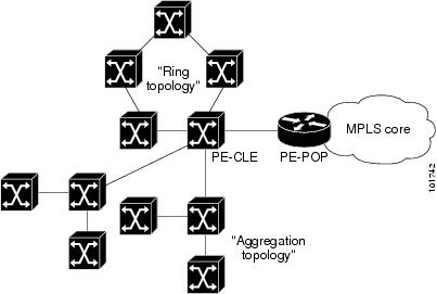
Service providers are now looking to offer L2 and L3 services that must integrate with a common MPLS infrastructure. ISC supports two basic L2 topologies to access L3 MPLS networks:
•
•
Figure 12-1 shows an example of these two basic L2 access topologies.
Figure 12-1 L2 Access Topologies
Creating a Ring of Three PE-CLE
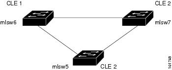
In its simplest form, the Ring Topology is a tripartite structure that comprises at least three PE- CLE. A PE-POP and a Multi-VRF CE can also be part of a Ring.
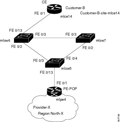
Figure 12-2 shows an example ring of three Catalyst 3550 switches: mlsw5, mlsw6, and mlsw7.
Figure 12-2 A Ring of Three PE-CLE
To create a Ring Topology in ISC, follow these steps:
Step 1
Step 2
Step 3
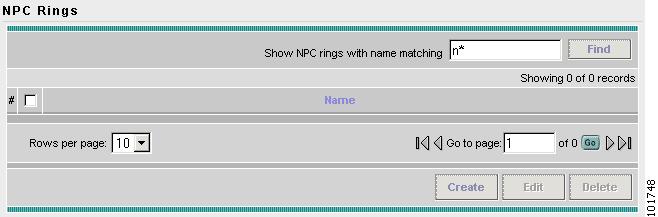
The NPC Rings window appears, as shown in Figure 12-3.
Figure 12-3 NPC Rings
Step 4
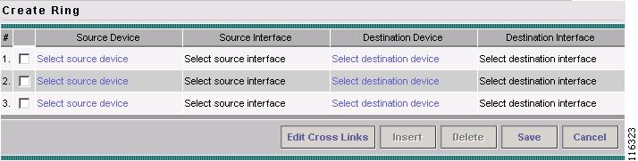
The Create Ring window appears, as shown in Figure 12-4.
Figure 12-4 Create Ring
Step 5
The Show Devices window appears, as shown in Figure 12-5.
Note
Figure 12-5 Show Devices
Step 6
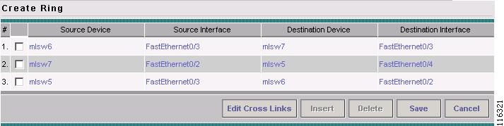
Step 7
The Create Ring window appears, as shown in Figure 12-6.
Figure 12-6 Create Ring
Step 8
Note
Step 9
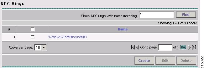
The NPC Rings window appears, as shown in Figure 12-7
Figure 12-7 NPC Rings
Proceed to Configuring NPC Ring Topology.
Configuring NPC Ring Topology
Figure 12-8 shows an example of the Ring Topology (three CLE) inserted between a CE (mlce14) and a PE-POP (mlpe4).
Figure 12-8 The Ring Topology
To configure end-to-end connectivity (CE > Ring (PE-CLE) > PE), follow these steps:
Step 1
Step 2
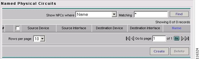
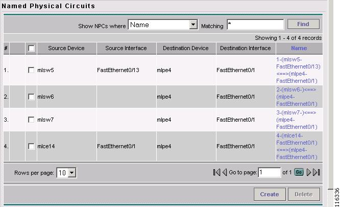
The Named Physical Circuits window appears, as shown in Figure 12-9.
Figure 12-9 Named Physical Circuits
Step 3
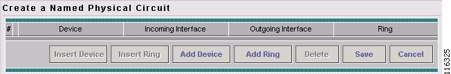
The Create Named Physical Circuits window appears, as shown in Figure 12-10.
Figure 12-10 Create a Named Physical Circuit
Step 4
The Select Devices window appears (not shown).
Step 5
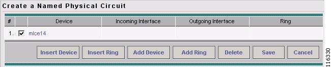
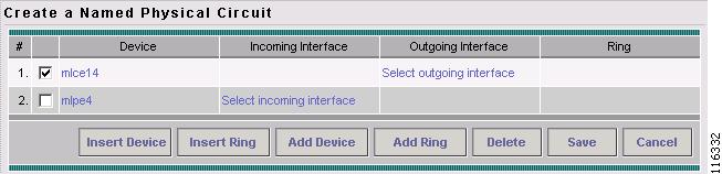
The Create a Named Physical Circuit window appears, as shown in Figure 12-11.
Figure 12-11 Create a Named Physical Circuit
Step 6
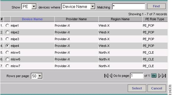
The Select Devices window appears, as shown in Figure 12-12.
Figure 12-12 Choose Devices
Step 7
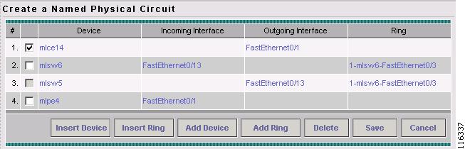
The Create a Named Physical Circuit window appears, as shown in Figure 12-13.
Figure 12-13 Create a Named Physical Circuit
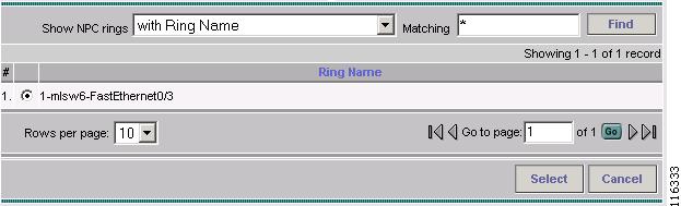
Step 8
The Show NPC Rings window appears, as shown in Figure 12-14.
Figure 12-14 Create a Named Physical Circuit
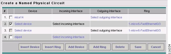
Step 9
The Create a Named Physical Circuit window appears, as shown in Figure 12-15.
Figure 12-15 Create a Named Physical Circuit
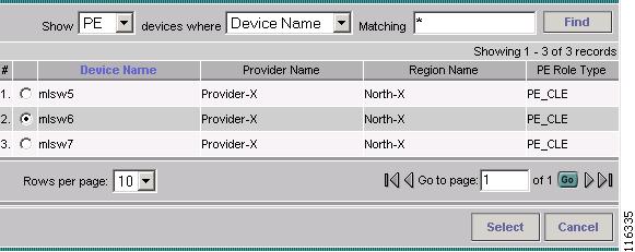
Step 10
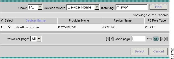
The Show PE Devices window appears, as shown in Figure 12-16.
Figure 12-16 Show PE Devices
Step 11
The Create a Named Physical Circuit window appears (not shown).
Step 12
Step 13
The Create a Named Physical Circuit window appears, as shown in Figure 12-17.
Figure 12-17 Create a Named Physical Circuit
Step 14
The Named Physical Interfaces window appears, with the Ring Topology displayed, as shown in Figure 12-18.
Figure 12-18 Named Physical Circuits
Ethernet-To-The-Home
This section describes how to configure Ethernet-To-The-Home (ETTH) using the IP Solution Center (ISC) provisioning process. This section contains the following sections:
ETTH Overview
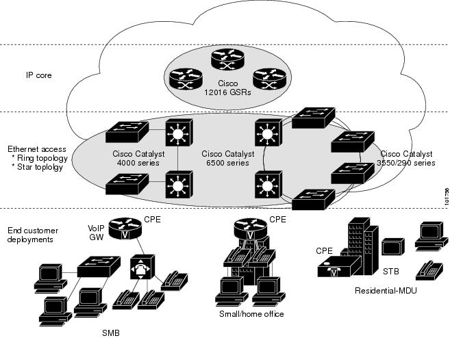
ETTH is part of the Cisco ETTx solution, which contains both ETTH and Ethernet-to-the-Business (ETTB). ETTB is supported in ISC with the L2VPN Metro Ethernet service feature. Unlike ETTB, whose customers are mainly business customers, ETTH is targeted at residential customers.
Figure 12-19 shows an overview of the Cisco ETTx solution.
Figure 12-19 Cisco ETTx Solution
From a provisioning standpoint, the main difference between ETTB and ETTH is the consideration of resource scalability. For example, with ETTB, each business customer is allocated one or more VLAN(s).
With ETTH, it is not practical to assign a unique VLAN to each residential customer. The practical solution is to have all, or a group of residential customers, share the same VLAN and use common technology, such as a private VLAN (PVLAN) or a protected port, to guarantee traffic isolation.
Another difference between ETTB and ETTH is that most of the ETTB customers use an Ethernet trunk port while ETTH customers use an access port. In ISC, the access port is fully supported, with CE present or with no CE.
ETTH needs to support multicast based services, such as video, on a shared media such as a ring. Typically, Internet Group Management Protocol (IGMP) with Multicast VLAN Registration (MVR) would be the technology used to support these services.
Access Domain Management
To provide more flexibility in managing an access domain, you can define a management VLAN. Once defined, the management VLAN is used to construct the list of VLANs allowed on the trunk port for all non-UNI ports.
You can also specify how the VLAN allowed list is constructed in a trunk port for a domain, if the list is not on the device. This feature is implemented for L2VPN DCPL parameter. It is available for Layer 2 access to MPLS VPN as well.
As a part of Layer 2 access management, ISC provides the ability to create MAC access lists by specifying the MAC addresses to be allowed or blocked.
ISC ETTH Implementation
The ISC MPLS VPN implementation of ETTH consists of the following three sub-features:
PVLAN or Protected Port
This feature is used to isolate traffic within a PVLAN. It prevents traffic from flowing between two UNIs.
•
•
Access Port
In ISC, the untagged Ethernet default is supported in the CE present and no CE scenarios. You can choose between two encapsulations: Dot1q and Default.
The Default encapsulation only indicates that the traffic comes in from the CE is untagged. The UNI, which is always a Dot1q port, puts a tag on it before transmitting it. UNI has two options to handle this untagged traffic. It functions as an access port or a trunk port. For this reason, the GUI adds one more item for you to choose.
IGMP with MVR
This feature applies to a very specific user service and network topology. It is used for multicast video on a hub and spoke or ring network. However, it is not up to ISC to decide when it is used. ISC only makes it available and the network application running above ISC must invoke it when needed.
Configuring ETTH
To configure ETTH in ISC MPLS VPN, follow these steps:
Step 1
Step 2
Step 3
Step 4
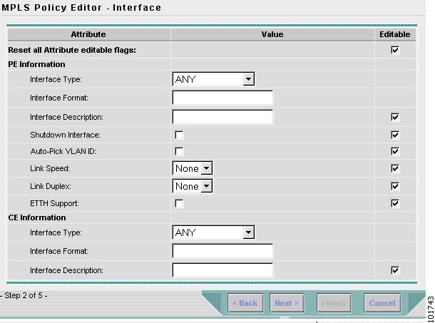
The MPLS Policy Editor - Interface window appears, as shown in Figure 12-20.
Figure 12-20 MPLS Policy Editor - Interface
Step 5
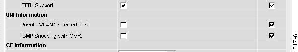
The ETTH UNI Information check boxes appear between the ETTH Support check box and the CE Information, as shown in Figure 12-21.
Figure 12-21 ETTH UNI Information
Step 6
Step 7
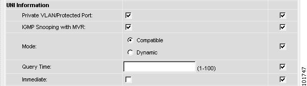
Three new UNI Information options appear, as shown in Figure 12-22.
Figure 12-22 ETTH UNI Information Options
Step 8
•
–
–
•
•
Step 9
Step 10
Step 11
Step 12
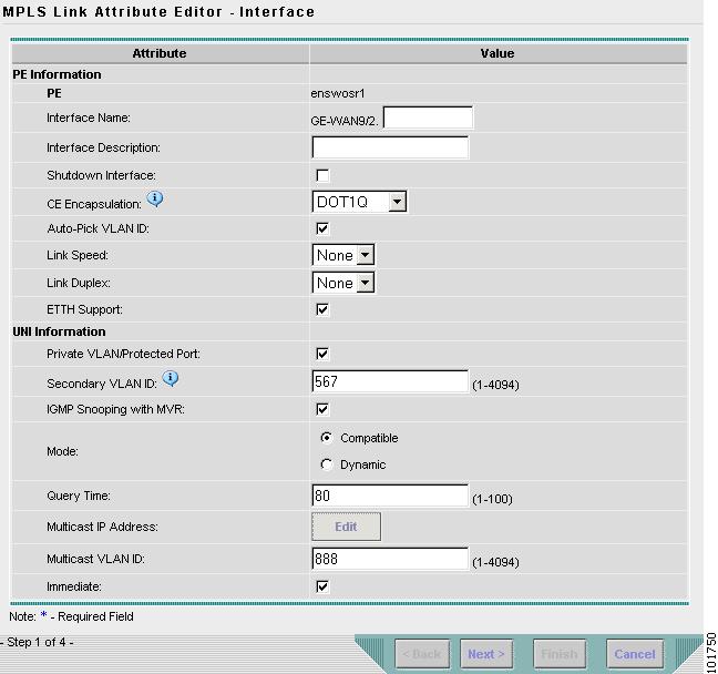
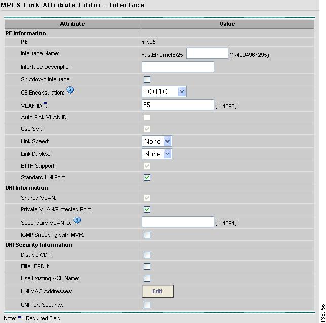
The MPLS Link Attribute Editor - Interface window appears, as shown in Figure 12-23.
Figure 12-23 MPLS Link Attribute Editor - Interface
Step 13
•
•
•
Step 14
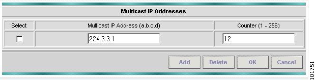
The Multicast IP Addresses dialog box appears, as shown in Figure 12-24.
Figure 12-24 Multicast IP Addresses
Step 15
•
•
Step 16
Step 17
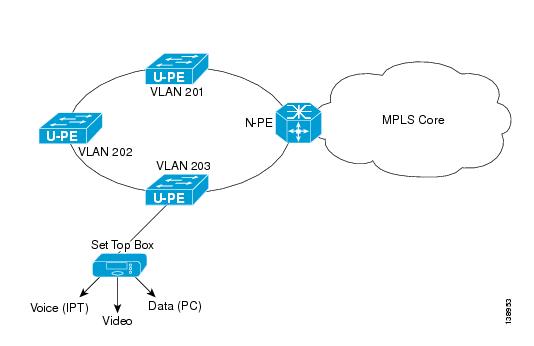
Residential Service
A group of residential customers can share the same VLAN on the same UNI switch with traffic isolation on different UNI interfaces. On an N-PE, a VRF SVI is defined for all the residential services from the same UNI switch (see Figure 12-25).
Figure 12-25 Residential Services
Policy for Residential Services Over Shared VLAN
A special policy must e created by enabling Shared VLAN.
Step 1
Step 2
Step 3
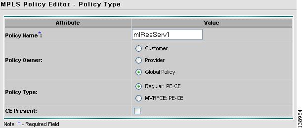
The Policy Type window appears (see Figure 12-26).
Figure 12-26 Policy Type
Step 4
Step 5
Step 6
Step 7
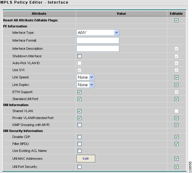
The MPLS Policy Editor - Interface window appears (see Figure 12-27).
Figure 12-27 Interface Settings
Step 8
Step 9
Step 10
Step 11
Some fields are now grayed-out.
Note
Step 12
Step 13
Step 14
Step 15
Service Requests
Step 1
Step 2
Step 3
The Select MPLS Policy window appears.
Step 4
The MPLS Service Request Editor window appears.
Step 5
Step 6
Step 7
Step 8
Step 9
The Interface window appears (see Figure 12-28).
Note
Figure 12-28 Interface Attributes
Step 10
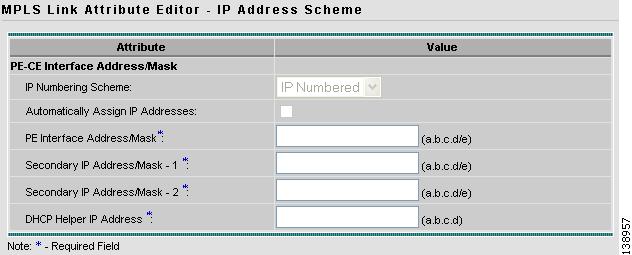
The IP Address Scheme window appears (see Figure 12-29).
Figure 12-29 Entering IP Address Scheme
Step 11
Step 12
Figure 12-30 Selecting Routing Information
Step 13
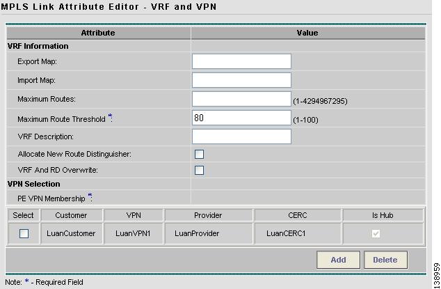
Figure 12-31 Selecting VRF and VPN Attributes
Step 14
Step 15
Step 16
Step 17