-
Cisco IP Solution Center MPLS VPN User Guide, 4.1
-
Index
-
Preface
-
Getting Started
-
Provisioning Unmanaged Multi-VRF CE
-
Creating Resource Pools
-
Defining VPNs and CERCs
-
MPLS VPN Service Policies
-
MPLS VPN Service Requests
-
Provisioning Regular PE-CE Links
-
Provisioning MVRFCE PE-CE Links
-
Provisioning Management VPN
-
Provisioning Cable Services
-
Provisioning Carrier Supporting Carrier
-
Provisioning Multiple Devices
-
Spanning Multiple Autonomous Systems
-
Creating Custom MPLS Reports
-
IP Solution Center - MPLS VPN
-
Service Request Transition States
-
Troubleshooting MPLS VPN
-
 Feedback
Table Of Contents
Provisioning MVRFCE PE-CE Links
MPLS VPN MVRFCE PE-CE Link Overview
Defining a VPN for the MVRFCE PE-CE Link
Creating MPLS VPN MVRFCE PE-CE Service Policies
Creating a MVRFCE PE-CE Service Policy
Creating a PE-NoCE Service Policy
Creating MPLS VPN MVRFCE PE-CE Service Requests
Creating a MVRFCE PE-CE Service Request
Creating a MVRFCE PE-NoCE Service Request
Provisioning MVRFCE PE-CE Links
This chapter describes how to configure MPLS VPN MVRFCE PE-CE links in the IP Solution Center (ISC) provisioning process. This chapter contains the following major sections:
•
MPLS VPN MVRFCE PE-CE Link Overview
•
•
MPLS VPN MVRFCE PE-CE Link Overview
This section contains the following sections:
To provision an MPLS VPN service in ISC, you must first create an MPLS VPN Service Policy. In ISC, a Service Policy is a set of default configurations for creating and deploying a Service Request.
ISC supports two MPLS VPN Service Policy Types: Regular PE-CE an MVRFCE PE-CE. The following scenarios focus on the MVRFCE PE-CE Policy Type.
An MVRFCE PE-CE Policy Type is a PE to CE link with three devices:
•
•
•
This Policy Type has two options:
•
•
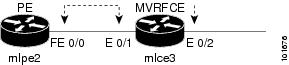
Figure 8-1 shows an example of an MVRFCE PE-CE link with three devices.
Figure 8-1 MVRFCE PE-CE Link
In an MVRFCE PE-CE link with CE Present enabled, interfaces FE 0/0, E 0/1, E 0/2 and FE 0/1 are configured as an MPLS VPN link in the Service Request process.
Figure 8-2 shows an example of a PE to MVRFCE link with no CE.
Figure 8-2 MVRFCE PE-CE Link with No CE
In an MVRFCE PE-CE link with CE Present disabled, interfaces FE 0/0, E 0/1, and E 0/2 are configured as an MPLS VPN link in the Service Request process.
Network Topology
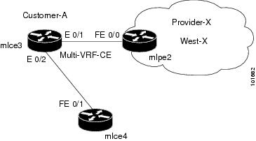
Figure 8-3 shows an overview of the network topology in which the MPLS VPN MVRFCE PE-CE links are created.
Figure 8-3 Network Topology for MPLS VPN MVRFCE PE-CE Scenarios
The network topology in Figure 8-3 illustrates the lab environment of a service provider (Provider-X) and one customer (Cust-A). There is one Region (West-X) and one PE (mlpe2.cisco.com). Each customer device (one MVRFCE and one CE) represents a Site (mlce3-Site and mlce4-Site).
Prerequisite Tasks
Before you can create a Service Policy in ISC, you must complete the following Inventory Management tasks:
Step 1
Step 2
Step 3
Step 4
Step 5
Step 6
Step 7
Infrastructure Data
In the subsequent MVRFCE PE-CE scenarios, the following infrastructure data is used:
•
•
•
•
•
•
•
•
•
•
•
•
–
–
–
–
–
•
–
–
–
•
–
–
–
•
–
–
Defining a VPN for the MVRFCE PE-CE Link
During service deployment, ISC generates the Cisco IOS commands to configure the logical VPN relationships.
At the beginning of the provisioning process, before creating a Service Policy, a VPN must be defined within ISC. The first element in a VPN definition is the name of the VPN.
To create a VPN Name, follow these steps:
Step 1
Step 2
The VPN window appears, as shown in Figure 8-4.
Figure 8-4 VPNs
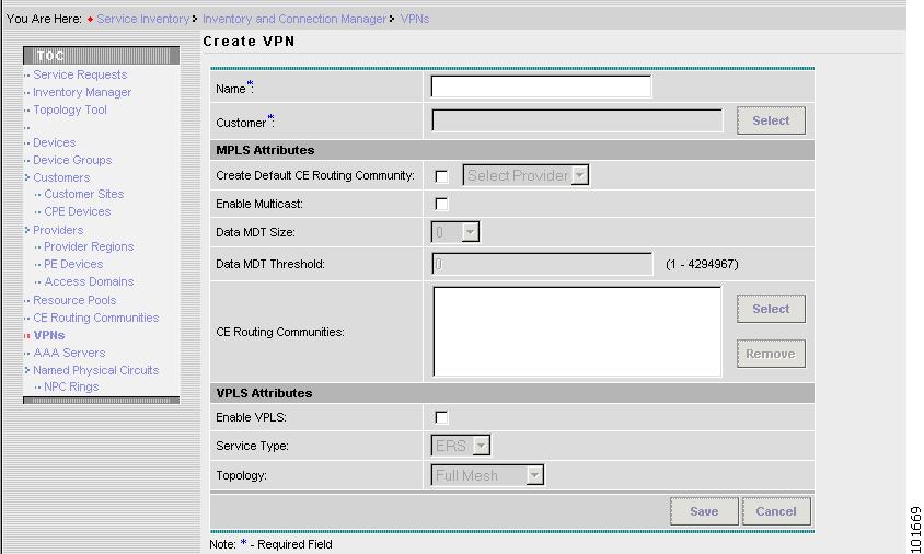
Step 3
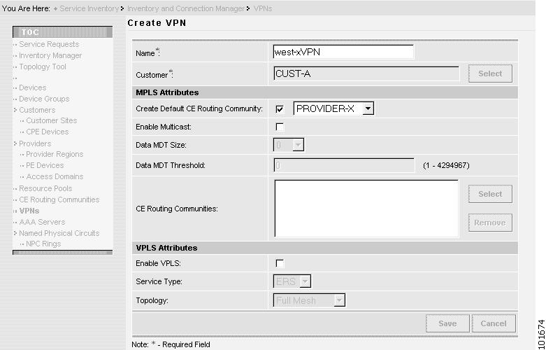
The Create VPN window appears, as shown in Figure 8-5.
Figure 8-5 Create VPN
Step 4
•
•
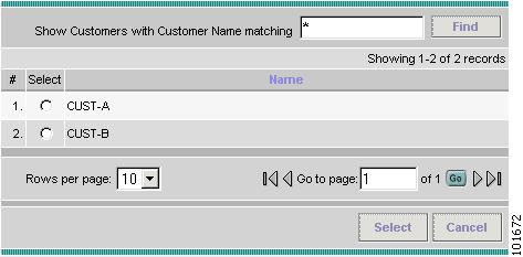
The Select Customer window appears, as shown in Figure 8-6.
Figure 8-6 Choose Customer
Step 5
Step 6
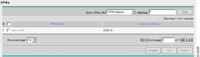
The VPNs window reappears, as shown in Figure 8-7.
Figure 8-7 VPNs
The VPN Name (west-xVPN) is associated with the Customer (Cust-A) in this new VPN definition.
Creating MPLS VPN MVRFCE PE-CE Service Policies
This section contains the following sections:
•
•
Creating a MVRFCE PE-CE Service Policy
To create a MVRFCE PE-CE Service Policy, follow these steps:
Step 1
Step 2
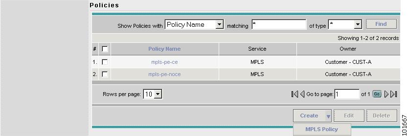
The Policies window appears, as shown in Figure 8-8.
Figure 8-8 Policies
Step 3
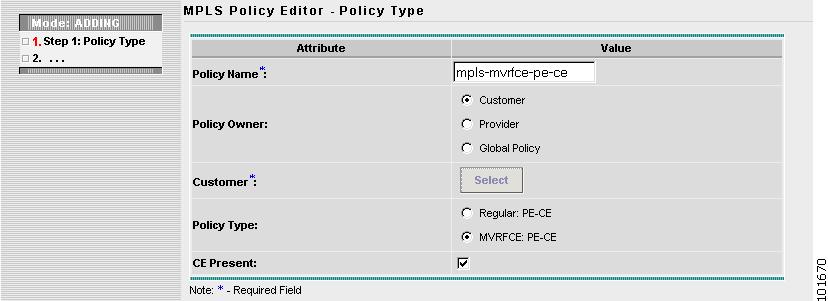
The MPLS Policy Editor - Policy Type window appears, as shown in Figure 8-9.
Figure 8-9 MPLS Policy Editor - Policy Type
Step 4
•
•
•
•
•
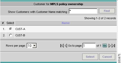
Step 5
The Customer for MPLS Policy ownership window appears, as shown in Figure 8-10.
Figure 8-10 Customer for MPLS Policy
Step 6
Step 7
The MPLS Policy Editor - PE Interface window appears, as shown in Figure 8-11.
Figure 8-11 The MPLS Policy Editor - PE Interface
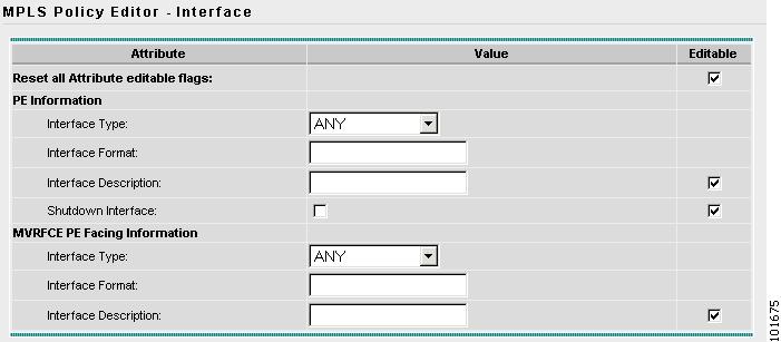
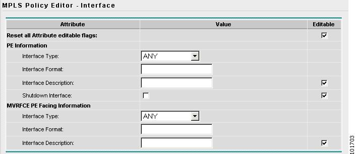
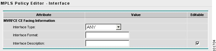
Step 8
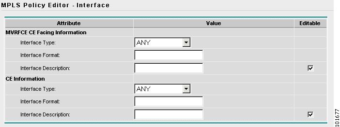
The MPLS Policy Editor - Interface window appears, as shown in Figure 8-11.
Figure 8-12 The MPLS Policy Editor - CE Interface
Step 9
Note
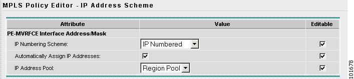
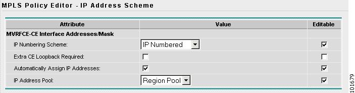
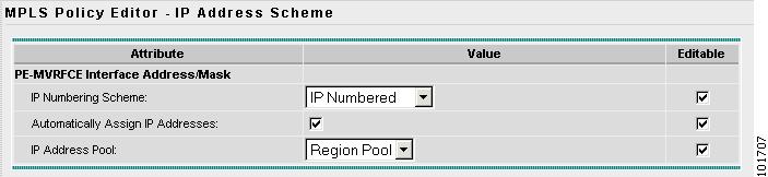
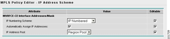
The MPLS Policy Editor - IP Address Scheme window appears, as shown in Figure 8-13.
Figure 8-13 The MPLS Policy Editor - IP Address Scheme
The MPLS Policy Editor - IP Address Scheme window appears, as shown in Figure 8-13.
Figure 8-14 The MPLS Policy Editor - IP Address Scheme
Step 10
•
•
•
Step 11
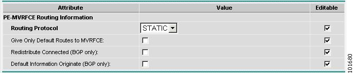
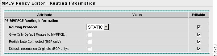
The MPLS Policy Editor - Routing Information window appears, as shown in Figure 8-15.
Figure 8-15 The MPLS Policy Editor - Routing Information
Step 12
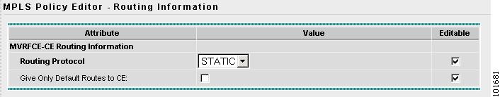
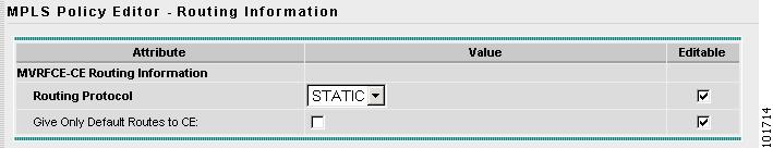
The MPLS Policy Editor - Routing Information window appears, as shown in Figure 8-16.
Figure 8-16 The MPLS Policy Editor - Routing Information
Step 13
Note
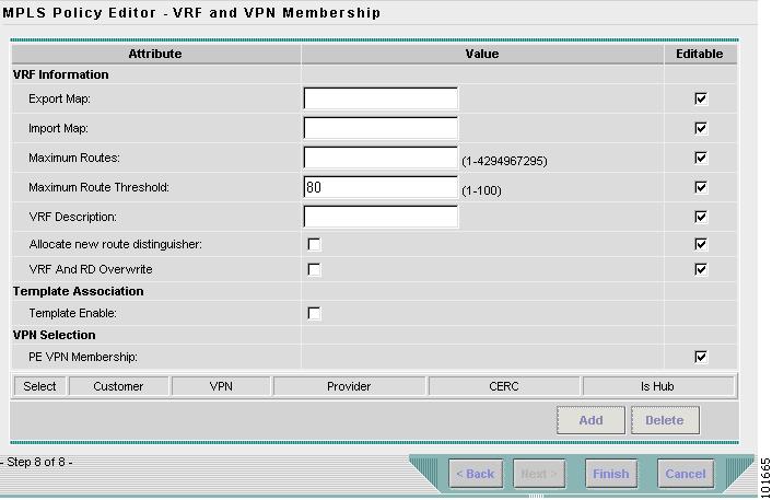
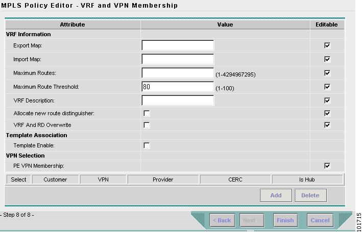
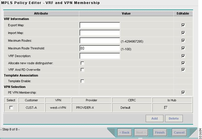
The MPLS Policy Editor - VRF and VPN Membership window appears, as shown in Figure 8-17.
Figure 8-17 The MPLS Policy Editor - VRF and VPN Membership
Step 14
Note
Step 15
The Policies window reappears, as shown in Figure 8-18.
Figure 8-18 Policies
The MPLS VPN MVRFCE PE-CE Service Policy is complete.
Creating a PE-NoCE Service Policy
To create a PE-NoCE Service Policy, follow these steps:
Step 1
Step 2
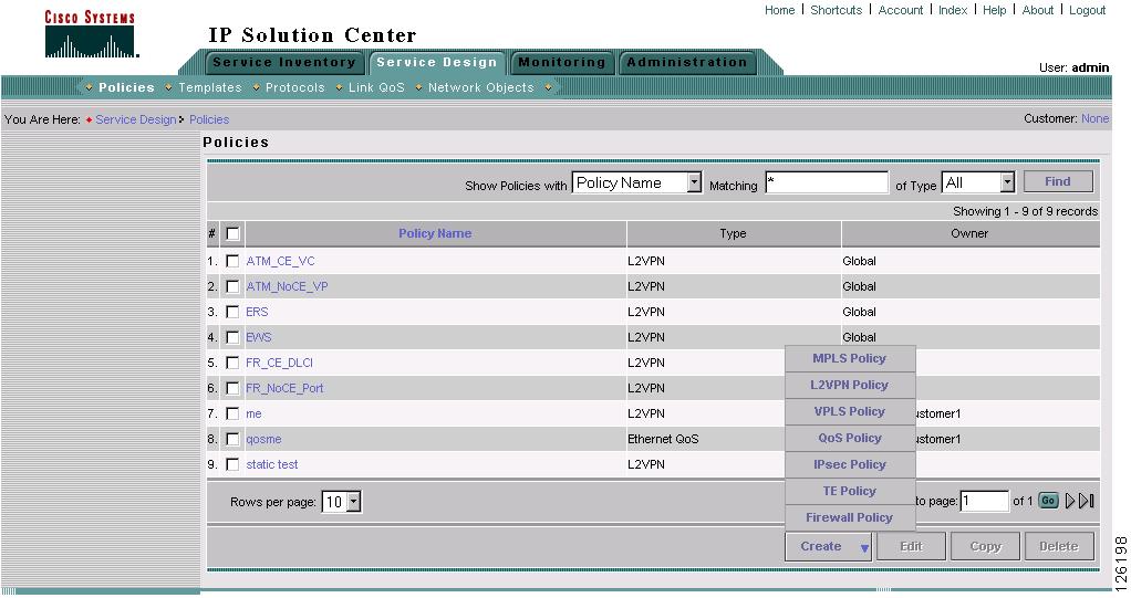
The Policies window appears, as shown in Figure 8-19.
Figure 8-19 Policies
Step 3
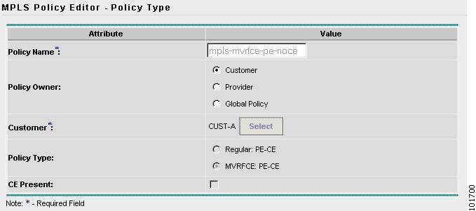
The MPLS Policy Editor - Policy Type window appears, as shown in Figure 8-20.
Figure 8-20 MPLS Policy Editor - Policy Type
Step 4
•
•
•
•
•
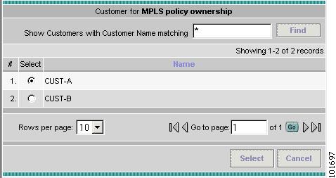
Step 5
The Customer for MPLS Policy window appears, as shown in Figure 8-21.
Figure 8-21 Customer for MPLS Policy
Step 6
Step 7
The MPLS Policy Editor - Interface window appears, as shown in Figure 8-22.
Figure 8-22 The MPLS Policy Editor - PE Interface
The MPLS Policy Editor - Interface window appears, as shown in Figure 8-23.
Step 8
Figure 8-23 The MPLS Policy Editor - CE Interface
Step 9
Note
The MPLS Policy Editor - IP Address Scheme window appears, as shown in Figure 8-24.
Figure 8-24 The MPLS Policy Editor - IP Address Scheme
Step 10
•
•
•
•
Step 11
The MPLS Policy Editor - IP Address Scheme window appears, as shown in Figure 8-25.
Figure 8-25 The MPLS Policy Editor - IP Address Scheme
Step 12
•
•
•
Click Next.
The MPLS Policy Editor - Routing Information window appears, as shown in Figure 8-26.
Figure 8-26 The MPLS Policy Editor - Routing Information
Step 13
The MPLS Policy Editor - Routing Information window appears, as shown in Figure 8-27.
Figure 8-27 The MPLS Policy Editor - Routing Information
Click Next to accept the defaults.
Note
The MPLS Policy Editor - VRF and VPN Membership window appears, as shown in Figure 8-28.
Figure 8-28 The MPLS Policy Editor - VRF and VPN Membership
Step 14
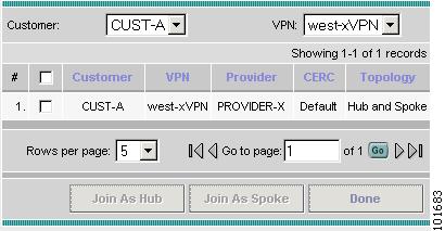
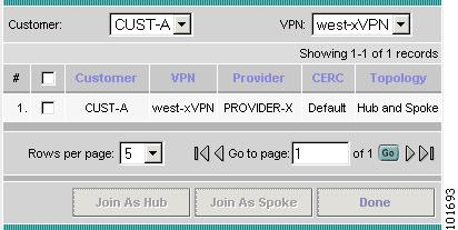
The VPN dialog box appears, as shown in Figure 8-29.
Figure 8-29 VPN Dialog Box
Click Join as Hub and then click Done.
The MPLS Policy Editor - VRF and VPN Membership window appears, as shown in Figure 8-30.
Figure 8-30 The MPLS Policy Editor - VRF and VPN Membership
Click Finish.
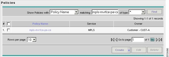
The Policies window reappears, as shown in Figure 8-31.
Figure 8-31 Policies
The MPLS VPN PE-NoCE Service Policy is complete.
Creating MPLS VPN MVRFCE PE-CE Service Requests
This section contains the following sections:
•
•
Creating a MVRFCE PE-CE Service Request
To create a MVRFCE PE-CE Service Request, follow these steps:
Step 1
Step 2
The Service Requests window appears, as shown in Figure 8-32.
Figure 8-32 Service Requests
Step 3
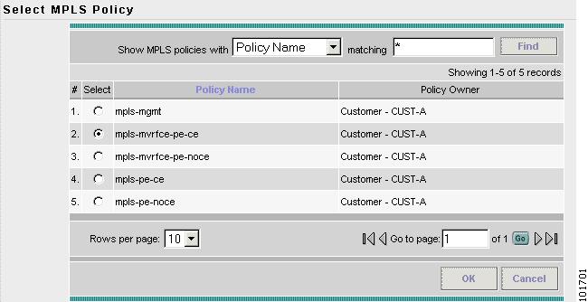
The Select MPLS Policy window appears, as shown in Figure 8-33.
Figure 8-33 Select MPLS Policy
Step 4
Step 5
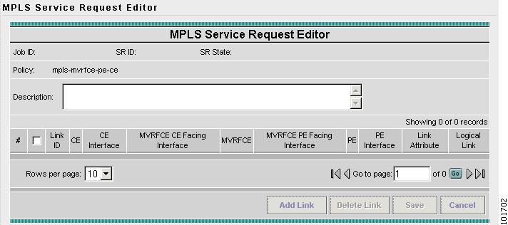
The MPLS Service Request Editor window appears, as shown in Figure 8-34.
Figure 8-34 MPLS Service Request Editor
Step 6
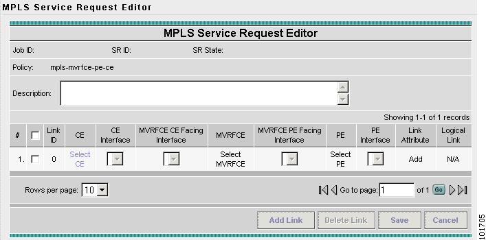
The MPLS Service Request Editor window appears, as shown in Figure 8-35.
Figure 8-35 MPLS Service Request Editor - Select CE
Step 7
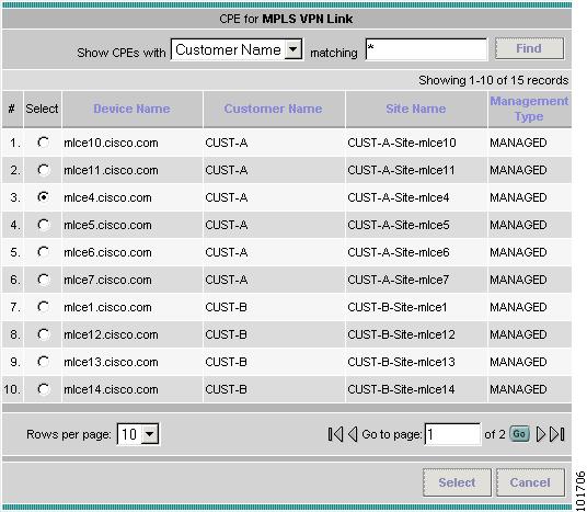
The CPE for MPLS VPN Link window appears, as shown in Figure 8-36.
Figure 8-36 CPE for MPLS VPN Link
Step 8
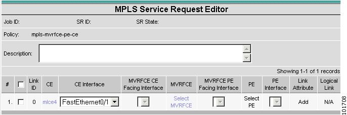
The MPLS Service Request Editor window appears, as shown in Figure 8-37.
Figure 8-37 MPLS Service Request Editor - Select MVRFCE
Step 9
Step 10
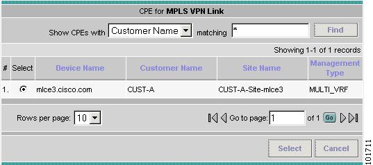
The MVRFCE for MPLS VPN Link window appears, as shown in Figure 8-38.
Figure 8-38 PE for MPLS VPN Link
Step 11
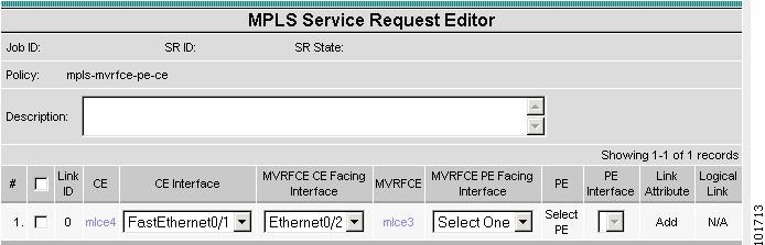
The MPLS Service Request Editor window appears, as shown in Figure 8-39.
Figure 8-39 MPLS Service Request Editor - Select MVRFCE CE Facing Interface
Step 12
Step 13
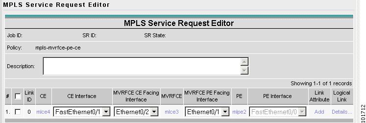
The MPLS Service Request Editor window appears, as shown in Figure 8-40.
Figure 8-40 PE for MPLS VPN Link
Step 14
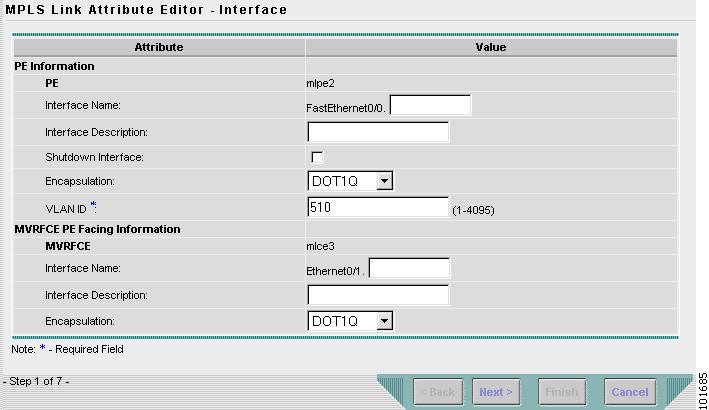
The MPLS Link Attribute Editor - Interface window appears, as shown in Figure 8-41.
Figure 8-41 MPLS Link Attribute Editor - Interface
PE Information
Step 15
Step 16
MVRFCE PE Facing Information
Step 17
Step 18
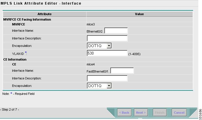
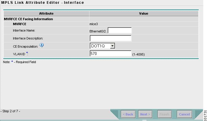
The MPLS Link Attribute Editor - Interface window appears, as shown in Figure 8-42.
Figure 8-42 MPLS Link Attribute Editor - Interface
MVRFCE CE Information
Step 19
Step 20
MVRFCE PE Facing Information
Step 21
Click Next.
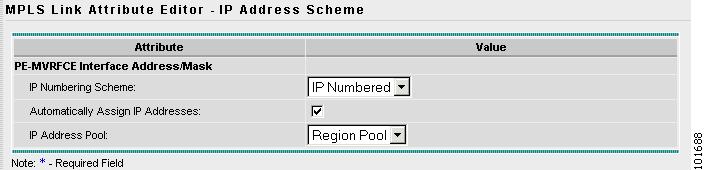
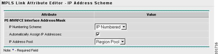
The MPLS Link Attribute Editor - IP Address Scheme window appears, as shown in Figure 8-43.
Figure 8-43 MPLS Link Attribute Editor - IP Address Scheme
Step 22
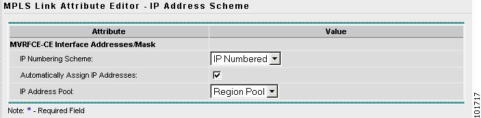
The MPLS Link Attribute Editor - IP Address Scheme window appears, as shown in Figure 8-44.
Figure 8-44 MPLS Link Attribute Editor - IP Address Scheme
Accept the defaults and click Next.
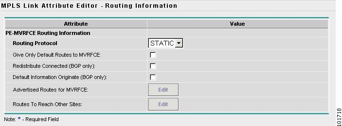
The MPLS Link Attribute Editor - Routing Information window reappears, as shown in Figure 8-45.
Figure 8-45 MPLS Link Attribute Editor - Routing Information
Step 23
The MPLS Link Attribute Editor - Routing Information window reappears, as shown in Figure 8-46.
Figure 8-46 MPLS Link Attribute Editor - Routing Information
Accept the defaults and click Next.
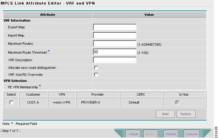
The MPLS Link Attribute Editor - VRF and VPN window appears, as shown in Figure 8-47.
Figure 8-47 MPLS Link Attribute Editor - VRF and VPN
Step 24
The MPLS Link Attribute Editor - VRF and VPN window appears, as shown in Figure 8-48.
Figure 8-48 MPLS Link Attribute Editor - VRF and VPN
Click Add to join VPN.
The MPLS Link Attribute Editor - VRF and VPN window reappears, as shown in Figure 8-49.
Figure 8-49 MPLS Service Request Editor
Step 25
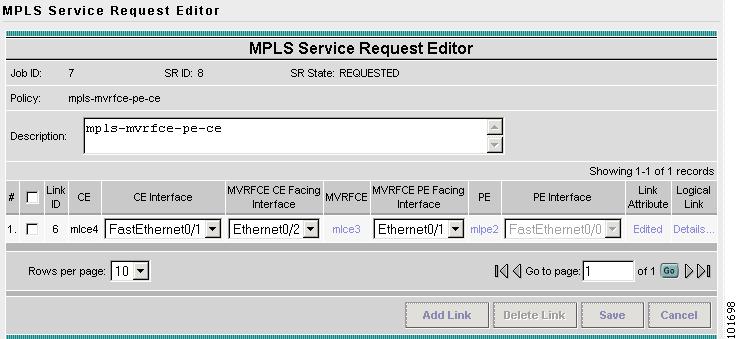
The MPLS Service Request Editor window reappears, as shown in Figure 8-50.
Figure 8-50 MPLS Service Request Editor
Step 26
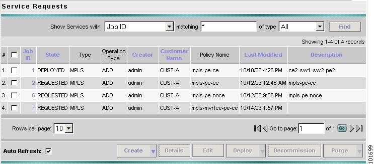
The MPLS Service Requests window reappears, as shown in Figure 8-51.
Figure 8-51 Service Request
The MPLS VPN MVRFCE PE-CE Service Request is in the Requested state and ready to deploy.
Creating a MVRFCE PE-NoCE Service Request
To create a MVRFCE PE-NoCE Service Request, follow these steps:
Step 1
Step 2
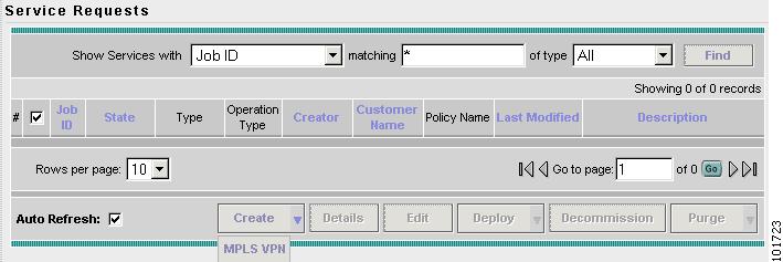
The Service Requests window appears, as shown in Figure 8-52.
Figure 8-52 Service Requests
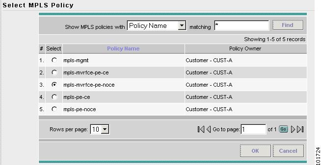
Step 3
The Select MPLS Policy window appears, as shown in Figure 8-53.
Figure 8-53 Select MPLS Policy
Step 4
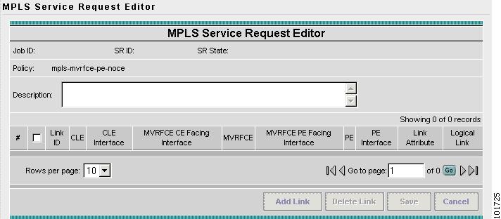
Step 5
The MPLS Service Request Editor window appears, as shown in Figure 8-54.
Figure 8-54 MPLS Service Request Editor
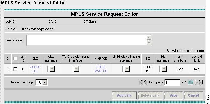
Step 6
The MPLS Service Request Editor window appears, as shown in Figure 8-55.
Figure 8-55 MPLS Service Request Editor - Select MVRFCE
Step 7
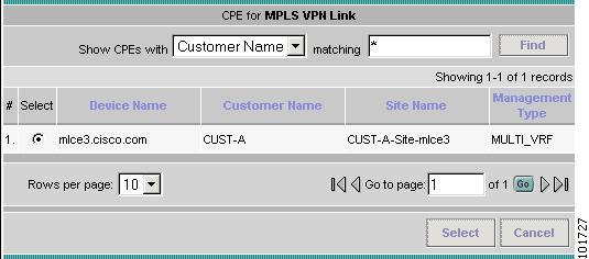
The CPE for MPLS VPN Link window appears, as shown in Figure 8-56.
Figure 8-56 CPE for MPLS VPN Link
Step 8
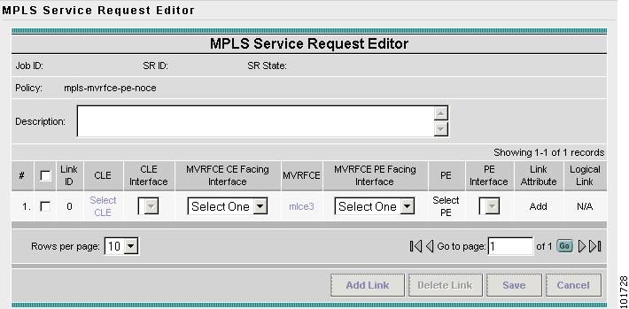
The MPLS Service Request Editor window appears, as shown in Figure 8-57.
Step 9
Figure 8-57 MPLS Service Request Editor - MVRFCE CE Facing Interface
Step 10
Step 11
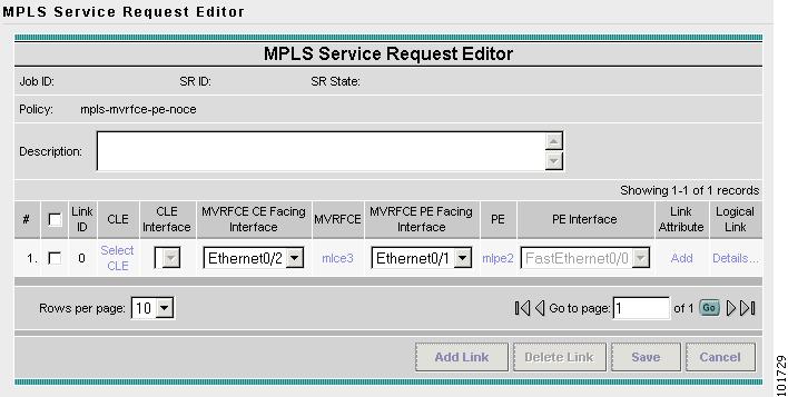
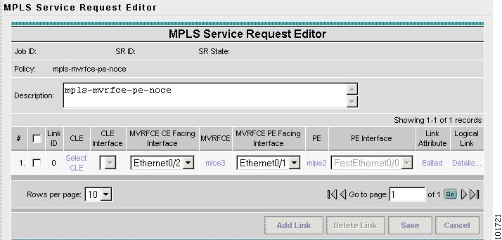
The MPLS Service Request Editor window appears, as shown in Figure 8-58.
Figure 8-58 MPLS Service Request Editor
Step 12
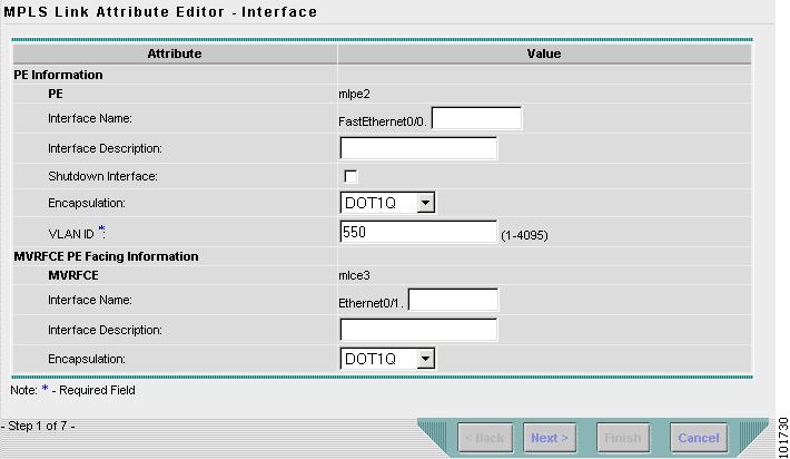
The MPLS Link Attribute Editor - Interface window appears, as shown in Figure 8-59.
Figure 8-59 MPLS Link Attribute Editor - Interface
PE Information
Step 13
Step 14
MVRFCE PE Facing Information
Step 15
Step 16
The MPLS Link Attribute Editor - Interface window appears, as shown in Figure 8-60.
Figure 8-60 MPLS Link Attribute Editor - Interface
MVRFCE CE Information
Step 17
Step 18
MVRFCE PE Facing Information
Step 19
Click Next.
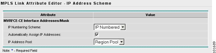
The MPLS Link Attribute Editor - IP Address Scheme window appears, as shown in Figure 8-61.
Figure 8-61 MPLS Link Attribute Editor - IP Address Scheme
Step 20
The MPLS Link Attribute Editor - IP Address Scheme window appears, as shown in Figure 8-62.
Figure 8-62 MPLS Link Attribute Editor - IP Address Scheme
Accept the defaults and click Next.
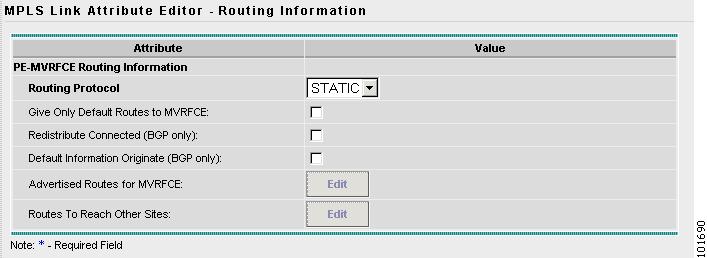
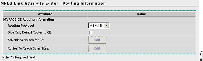
The MPLS Link Attribute Editor - Routing Information window reappears, as shown in Figure 8-63.
Figure 8-63 MPLS Link Attribute Editor - Routing Information
Step 21
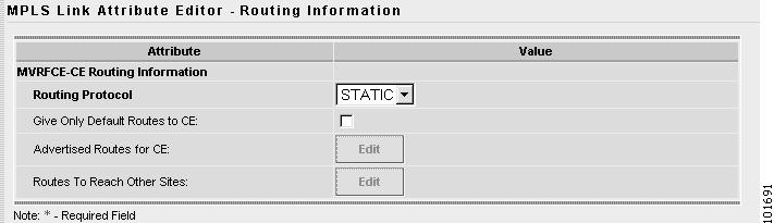
The MPLS Link Attribute Editor - Routing Information window reappears, as shown in Figure 8-64.
Figure 8-64 MPLS Link Attribute Editor - Routing Information
Accept the defaults and click Next.
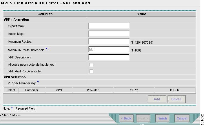
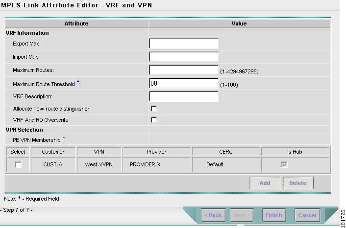
The MPLS Link Attribute Editor - VRF and VPN window appears, as shown in Figure 8-65.
Figure 8-65 MPLS Link Attribute Editor - VRF and VPN
Step 22
Step 23
The MPLS Service Request Editor window reappears, as shown in Figure 8-66.
Figure 8-66 MPLS Service Request Editor
Step 24
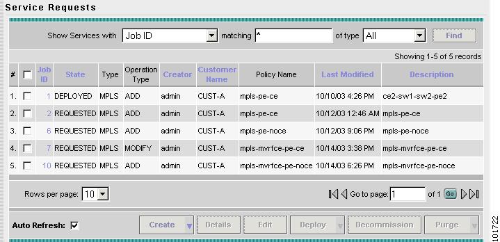
The MPLS Service Requests window reappears, as shown in Figure 8-67.
Figure 8-67 Service Request
The MPLS VPN MVRFCE PE-NoCE Service Request is in the Requested state and ready to deploy.