-
Cisco IP Solution Center MPLS VPN User Guide, 4.1
-
Index
-
Preface
-
Getting Started
-
Provisioning Unmanaged Multi-VRF CE
-
Creating Resource Pools
-
Defining VPNs and CERCs
-
MPLS VPN Service Policies
-
MPLS VPN Service Requests
-
Provisioning Regular PE-CE Links
-
Provisioning MVRFCE PE-CE Links
-
Provisioning Management VPN
-
Provisioning Cable Services
-
Provisioning Carrier Supporting Carrier
-
Provisioning Multiple Devices
-
Spanning Multiple Autonomous Systems
-
Creating Custom MPLS Reports
-
IP Solution Center - MPLS VPN
-
Service Request Transition States
-
Troubleshooting MPLS VPN
-
 Feedback
Table Of Contents
About IP Addresses in Cisco ISC
Creating MPLS Service Policy for PE-to-CE Link
Specifying PE and CE Interface Parameters
Using Existing Loopback Interface Number
Specifying Routing Protocol for a Service
Giving Only Default Routes to CE
Defining an MVRFCE PE-CE Service Policy
Defining the Service Policy VRF and VPN Information
MPLS VPN Service Policies
This chapter describes how to use the IP Solution Center (ISC) GUI to define MPLS VPN Service Policies. This chapter contains the following major sections:
•
Creating MPLS Service Policy for PE-to-CE Link
•
Service Policy Overview
Provisioning an MPLS VPN begins with defining a service policy. A service policy can be applied to multiple PE-CE links in a single service request.
A network operator defines service policies. A service operator uses a service policy to create service requests. Each service request contains a list of PE-CE links. When a service operator creates a service request, the operator sees only the policy information required to be completed. All the other necessary information is filled in by the service policy itself (as well as the Auto Discovery process).
Creating MPLS VPN in ISC
At its simplest, a virtual private network (VPN) is a collection of sites that share the same routing table. A VPN is also a framework that provides private IP networking over a public infrastructure such as the Internet. In IP Solution Center (ISC), a VPN is a set of customer sites that are configured to communicate through a VPN service. A VPN is defined by a set of administrative policies.
A VPN is a network in which two sites can communicate over the provider's network in a private manner; that is, no site outside the VPN can intercept their packets or inject new packets. The provider network is configured such that only one VPN's packets can be transmitted through that VPN—that is, no data can come in or out of the VPN unless it is specifically configured to allow it. There is a physical connection from the provider edge network to the customer edge network, so authentication in the conventional sense is not required.
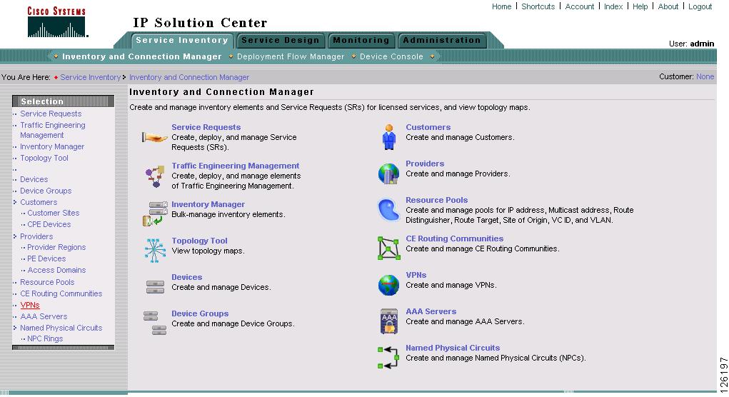
To create a new VPN in ISC: MPLS, follow these steps:
Step 1
Step 2
Step 3
The Inventory and Connection Manager window appears (see Figure 5-1).
Figure 5-1 Creating an MPLS VPN in ISC
Step 4
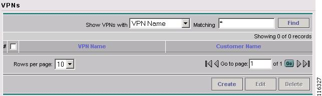
The VPNs dialog box appears (see Figure 5-2).
Figure 5-2 Viewing Existing VPNs or Creating a New VPN
Step 5
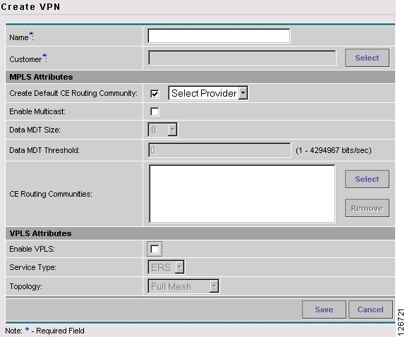
The Create VPN dialog box appears (see Figure 5-3).
Figure 5-3 Creating an MPLS VPN in ISC
Step 6
Step 7
a.
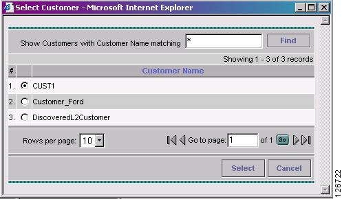
The Select Customer dialog box appears (see Figure 5-4).
Figure 5-4 Selecting a Customer for the VPN
b.
Step 8
Step 9
An IP address that starts with the binary prefix 1110 is identified as a multicast group address. There can be more than one sender and receiver at any time for a given multicast group address. The senders send their data by setting the group address as the destination IP address. It is the responsibility of the network to deliver this data to all the receivers in the network who are listening to that group address.
Note
a.
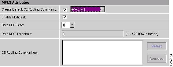
ISC enables two additional fields required to configure multicast routing (see Figure 5-5).
Figure 5-5 Selecting a Customer for the VPN
To implement multicast routing, ISC employs the concept of a multicast domain (MD), which is a set of VRFs associated with interfaces that can send multicast traffic to each other. A VRF contains VPN routing and forwarding information for unicast. A multicast VRF contains multicast routing and forwarding information and supports multicast routing.
b.
MDT refers to a multicast distribution tree (MDT). The MDT defined here carries multicast traffic from customer sites associated with the multicast domain.
c.
The data MDT contains a range of multicast group addresses and a bandwidth threshold. Thus, whenever a CE behind a multicast-VRF exceeds that bandwidth threshold while sending multicast traffic, the PE sets up a new data MDT for the multicast traffic from that source. The PE informs the other PEs about this data MDT and, if they have receivers for the corresponding group, the other PEs join this data MDT.
Step 10
a.
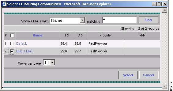
The Select CE Routing Communities dialog box appears (see Figure 5-6).
Figure 5-6 Selecting a CERC
b.
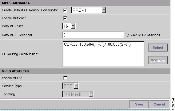
You return to the Create VPN dialog box, where the new CERC selection appears, along with its hub route target (HRT) and spoke route target (SRT) values (see Figure 5-7).
Figure 5-7 New CERC Selected
Step 11
Step 12
Step 13
Step 14
You have successfully created a VPN, as shown in the Status display in the lower left corner of the VPNs dialog box.
Creating Service Policies
Provisioning an MPLS VPN begins with defining a service policy. A service policy can be applied to multiple PE-CE links in a single service request.
A network operator defines service policies. A service operator uses a service policy to create service requests. Each service request contains a list of PE-CE links. When a service operator creates a service request, the operator sees only the policy information required to be completed. All the other necessary information is filled in by the service policy itself (as well as the Auto Discovery process).
Service Policy Editor
When you define a service policy for ISC, you are presented with a series of dialog boxes that allow you to specify the parameters for each major category required to complete an MPLS service request. The Service Policy editor presents three columns: Attribute, Value, and Editable:
•
The Attribute column displays the names of each parameter that you need to define for each major category (for example, IP addresses or routing protocols).
•
The Value column displays the fields and other selectable items that correspond to each parameter and option.
The type of dialog box that is invoked when you edit an attribute depends on the type of attribute. In some cases, the value is a simple string value or integer value, in which case a single text entry field appears. In other cases, the value is complex or consists of multiple values, such as an IP address. In these cases, a dialog box appears so you can specify the required values. The values you enter are validated; when invalid values are entered, you receive notification of the invalid values. In other cases, you will be presented with check boxes that will allow you to enable or disable a particular option.
Note
There is a parent-child relationship between some attributes. In these cases, changing the value of a parent attribute can enable or disable the child attributes. For example, changing the value of the PE encapsulation could result in enabling or disabling the DLCI (data link connection identifier), VLAN ID, ATM circuit identifiers, and the tunnel source and destination address attributes.
•
The Editable column allows the network operator to indicate the attributes that are likely to change across multiple service requests. When attributes are checked as editable, only those attributes will be made available to the service operator when creating or modifying service requests with that service request policy.
When an attribute category is set to be editable, all the related and child attributes are also editable attributes.
About IP Addresses in Cisco ISC
Within a VPN (or extranet), all IP addresses must be unique. Customer IP addresses are not allowed to overlap with provider IP addresses. Overlap is possible only when two devices cannot see each other; that is, when they are in isolated, non-extranet VPNs.
The ISC: MPLS software assumes that it has an IP address pool to draw addresses from. The only way to guarantee that the product can use these addresses freely is if they are provider IP addresses.
Predefining a unique section (or sections) of IP address space for the PE-CE links is the only way to ensure stable security. Thus, because of the security and maintenance issues, Cisco does not recommend using customer IP addresses on the PE-CE link.
Creating MPLS Service Policy for PE-to-CE Link
To create an MPLS service policy for a PE-to-CE link, follow these steps:
Step 1
Step 2
Step 3
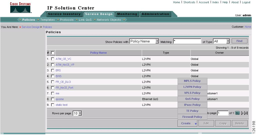
The Policies window appears (see Figure 5-8).
Figure 5-8 Creating a New Service Policy
Step 4
The MPLS Policy Type dialog box appears (see Figure 5-9).
Figure 5-9 Defining the MPLS Service Policy
Step 1
Step 2
There are three types of MPLS policy ownership:
•
•
•
This ownership has relevance when the ISC Role-Based Access Control (RBAC) comes into play. For example, an MPLS policy that is customer-owned can only be seen by operators who are allowed to work on this customer-owned policy.
Similarly, operators who are allowed to work on a provider's network can view, use, and deploy a particular provider-owned policy.
Step 3
Step 4
There are two policy types for MPLS policies:
•
•
Step 5
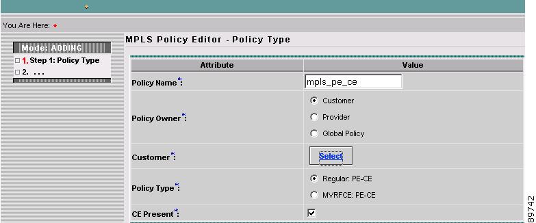
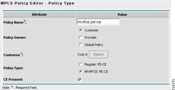
If you do not choose the CE Present check box, ISC asks the service operator, during service activation, only for the PE-CLE or the PE-POP router and customer-facing interface.
Step 6
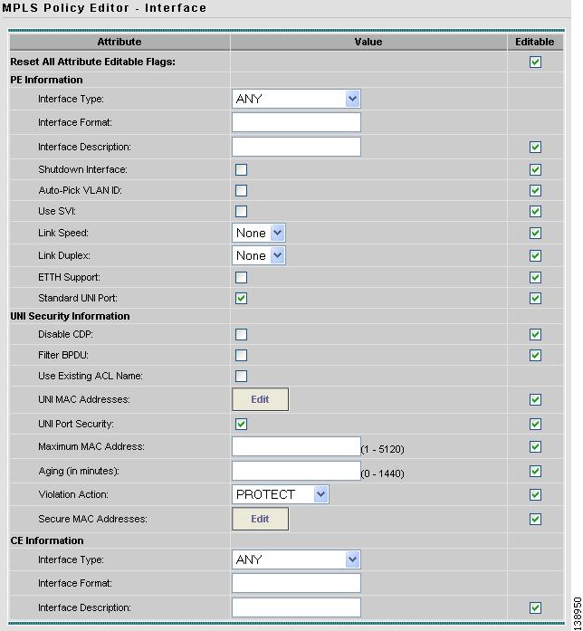
Specifying PE and CE Interface Parameters
The MPLS Policy Interface dialog box appears (see Figure 5-10).
Tip
If you want to specify the device interface information for this service policy when the service request is created, leave the fields as they are currently set by default, then click Next.Figure 5-10 Specifying the PE UNI Security, and CE Interface Parameters
To specify the PE, UNI Security, and CE interface information for this MPLS policy:
PE Interface Information
Step 1
IP Solution Center supports the following interface types (for both PEs and CEs):
•
•
•
•
•
•
•
•
•
•
•
•
•
•
•
•
•
•
Step 2
Specify the format in the standard nomenclature: slot number/port number (for example, 1/0 indicates that the interface is located at slot 1, port 0).
This is especially useful to specify here if you know that the link will always go through a particular interface's slot/port location on all or most of the network devices in the service. If this parameter is left editable, it can be changed when the service operator creates the service request.
You can also specify the Interface Format as a Channelized Interface:
•
•
•
Step 3
Step 4
Step 5
When you choose an interface type, the Encapsulation field displays a drop-down list of the supported encapsulation types for the specified interface type.
Table 5-1 shows the protocol encapsulations available for each of the supported interface types.
Step 6
Step 7
Step 8
Step 9
Step 10
Step 11
UNI Security Information
Step 12
Step 13
Step 14
Step 15
Step 16
a.
b.
c.
PROTECT
RESTRICT
SHUTDOWNd.
CE Interface Information
Step 17
Step 18
Step 19
Step 20
Step 21
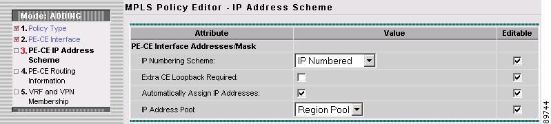
Specifying IP Address Scheme
The MPLS Policy Interface Address Selection dialog box appears (see Figure 5-11). This lets you specify the IP address scheme you want to use for this service policy.
Figure 5-11 Specifying the IP Address Scheme
Step 1
IP Numbering Scheme
A point-to-point link between two routers can be either a numbered IP address or an unnumbered IP address. The service provider must determine whether to use numbered or unnumbered IP addresses for the PE-CE link. Defining the link to use unnumbered addresses can save precious IP addresses because many interfaces can borrow the same IP address.
You can choose among two options: IP Numbered or IP Unnumbered.
•
If you choose IP numbered and choose to not use automatically assigned IP addresses, you can enter the IP addresses for the PE interface and CE interface in the fields provided. Entering the IP addresses in these fields forces the MPLS VPN software to use the indicated addresses.
If you choose IP numbered and also enable the Automatically Assign IP Address check box, ISC: MPLS checks for the presence of the corresponding IP addresses in the router's configuration file. If the addresses are present and they are in the same subnet, ISC uses those addresses (and does not allocate them from the address pool). If the IP addresses are not present in the configuration file, ISC picks IP addresses from a /30 subnet point-to-point IP address pool.
•
IP addresses are drawn from the loopback IP address pool. An unnumbered IP address means that each interface "borrows" its address from another interface on the router (usually the loopback interface). Unnumbered addresses can only be used on point-to-point WAN links (such as Serial, Frame, and ATM), not on LAN links (such as Ethernet). If using IP unnumbered, then both the PE and CE must use the same IP unnumbered addressing scheme. When you choose IP unnumbered, ISC: MPLS creates a static route for the PE-CE link.
When you choose IP unnumbered, ISC: MPLS automatically creates a loopback interface (unless a loopback interface already exists with the correct attributes). For related information, see Using Existing Loopback Interface Number.
If you choose IP unnumbered and choose to not use automatically assigned IP addresses, you can enter the IP addresses for the PE interface and CE interface in the fields provided. Entering the IP addresses in these fields forces the ISC: MPLS software to use the indicated addresses.
Step 2
Extra CE Loopback Required
Even though a numbered IP address does not require a loopback address, ISC software provides the option to specify than an extra CE loopback interface is required. This option places an IP address on a CE router that is not tied to any physical interface.
If you enable Extra CE Loopback Required, you can enter the CE loopback address.
Step 3
Automatically Assign IP Address
If you choose IP unnumbered and also enable the Automatically Assign IP Address check box, ISC picks two IP addresses from a /32 subnet point-to-point IP address pool.
If you choose IP numbered and also enable the Automatically Assign IP Address check box, ISC checks for the presence of the corresponding IP addresses in the router's configuration file. If the addresses are present and they are in the same subnet, ISC uses those addresses (and does not allocate them from the address pool). If the IP addresses are not present in the configuration file, ISC picks IP addresses from a /30 subnet point-to-point IP address pool.
Step 4
IP Address Pool
The IP Address Pool option gives the service operator the ability to have ISC automatically allocate IP addresses from the IP address pool attached to the Region. Prior to defining this aspect of the service policy, the Region must be defined and the appropriate IP address pools assigned to the Region.
You can specify IP address pool information for point-to-point (IP numbered) PE-CE links.
IP unnumbered addresses are drawn from the loopback IP address pool. An unnumbered IP address means that each interface "borrows" its address from another interface on the router (usually the loopback interface). Unnumbered addresses can only be used on point-to-point WAN links (such as Serial, Frame, and ATM), not on LAN links (such as Ethernet). If using IP unnumbered, then both the PE and CE must use the same IP unnumbered addressing scheme.
Step 5
Using Existing Loopback Interface Number
On each PE, there is usually only one loopback interface number per VRF for interfaces using IP unnumbered addresses. However, if provisioning an interface using IP unnumbered addresses and manually assigned IP addresses, it is possible to have more than one loopback interface number under the same VRF. When using automatically-assigned IP addresses for provisioning IP unnumbered addresses, ISC associates the first loopback number with the same VRF name to the interface. If no loopback number already exists, ISC creates one.
If a service provider wants ISC to use an existing loopback interface number (for example, Loopback0), the service provider must modify the loopback interface description line in the configuration files for the pertinent routers (PE or CE).
To use the existing loopback interface number, you must modify the loopback interface description line so that it includes the keyword VPN-SC, as shown in the following example of a router configuration file.
Note
interface Loopback0description by VPN-SCip vrf forwarding <VRF_name> ; This line is required on the PE onlyip address 209.165.202.129 255.255.255.224You can use an existing loopback interface number only when the interface configuration meets these conditions: it must be a WAN serial interface using IP unnumbered addresses.
ISC selects loopback interface numbers by sequence. ISC uses the first loopback interface number that meets the requirement—for a CE, it is inclusion of the VPN-SC keyword; for a PE, it is the matching VRF name.
For example, if loopback1 and loopback2 include the VPN-SC keyword, but loopback3 does not, adding the VPN-SC keyword to loopback3 will not force ISC to choose loopback3 for the unnumbered interface when using automatically assigned addresses. Loopback1 will be chosen instead. The only way to choose a specific loopback interface number is to use a manually assigned IP address that matches the desired loopback interface number.
Note
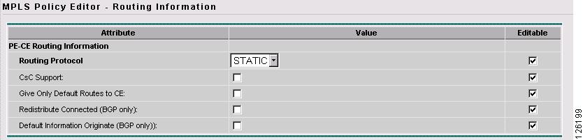
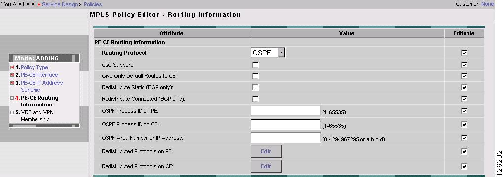
Specifying Routing Protocol for a Service
You can now specify the routing protocol information for this service policy (see Figure 5-12).
The routing protocol you choose must run on both the PE and the CE. You can choose any one of the following protocols:
•
•
•
•
•
•
To specify a routing protocol for the PE-CE link:
Step 1
When you choose a particular routing protocol, the related parameters for that protocol are displayed.
Step 2
Step 3
Redistribution of IP Routes
Route redistribution is the process of taking routing information from one source and importing that information into another source. Redistribution should be approached with caution. When you perform route redistribution, you lose information. Metrics must be arbitrarily reset. For example, if a group of RIP routes with a metric of five hops is redistributed into IGRP, there is no way to translate the five hop RIP metric into the composite metric of IGRP. You must arbitrarily choose a metric for the RIP routes as they are redistributed into IGRP. Also, when redistribution is performed at two or more points between two dynamic routing protocol domains, routing loops can occur.
CSC Support
To define a Service Policy with Carrier Supporting Carrier (CSC), choose the CSC Support check box from the MPLS Policy Editor - Routing Information. When CSC Support is checked, the CSC functionality is enabled to the MPLS VPN service. Provisioning CSC is explained in "Provisioning Carrier Supporting Carrier."
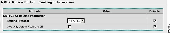
Giving Only Default Routes to CE
When you enable the Give only default routes to CE option, you indicate whether the site needs full routing or default routing. Full routing is when the site must know specifically which other routes are present in the VPN. Default routing is when it is sufficient to send all packets that are not specifically for your site to the VPN.
If you choose this option, ISC configures the default-info originate command on the PE router under the running protocol (for RIP, OSPF, or EIGRP). For Static, ISC configures an ip route 0.0.0.0 0.0.0.0 <out-going interface name> command on the CE router.
A device can only have one default route. Therefore, the VPN can use a default route, but only on condition that the customer site does not already have a different one. The most common reason to already have a default route is that the site has an Internet feed that is independent of the VPN.
If the CE site already has Internet service, the CE can either route all packets to unknown destinations to the Internet or learn all the routes in the Internet. The obvious choice is to route all packets to unknown destinations to the Internet. If a site has an Internet feed, it may already have a default route. Under such conditions, setting the VPN as the default route is incorrect; the VPN should only route packets meant for other VPN sites.
Static Protocol Chosen
Static routing refers to routes to destinations that are listed manually in the router. Network reachability in this case is not dependent on the existence and state of the network itself. Whether a destination is up or down, the static routes remain in the routing table and traffic is still sent to that destination.
When you choose Static as the protocol, four options are enabled: CSC Support, Give Only Default Routes to CE, Redistribute Connected (BGP only), and Default Information Originate (BGP only) (see Figure 5-12).
Note
Figure 5-12 Specifying the Static Routing Protocol
Step 1
Step 2
When you enable the Give only default routes to CE option with static route provisioning on the PE-CE link, ISC creates a default route on the CE that points to the PE. The VRF static route to the CE site is redistributed into BGP to other sites in the VPN.
When you choose this option, the default route (0.0.0.0/32) is automatically configured; the site contains no Internet feed or any other requirement for a default route. When the site encounters a packet that does not route locally, it can send the packet to the VPN.
If you choose this option, ISC configures the default-info originate command on the PE router under the running protocol (for RIP, OSPF, or EIGRP). For Static, ISC configures an ip route 0.0.0.0 0.0.0.0 <out-going interface name> command on the CE router.
Step 3
When you enable the Redistribute Connected option, the connected routes (that is, the routes to the directly connected PEs or CEs) are distributed to all the other CEs in that particular VPN. This option is meant for IBGP if the routing protocol between PE-CE is a non-BGP protocol. For example, if the routing protocol is RIP, OSPF, EIGRP, or Static, the option is meant for the router bgp that is configured on the PE for the MPLS core. On the PE router, there is one router bgp process running at all times for MPLS. This option is also for BGP.
Tip
Step 4
The Default Information Originate option is required, especially in the hub and spoke topology because each spoke must be able to communicate with every other spoke (by injecting a default route in the hub PE to the spoke PEs).
Step 5
The MPLS Policy VRF and VPN Membership dialog box appears. To proceed, see Defining the Service Policy VRF and VPN Information.
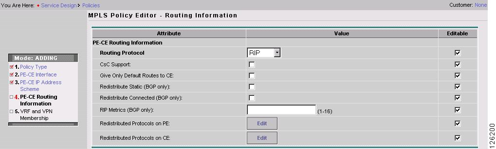
RIP Protocol Chosen
The Routing Information Protocol (RIP) is a distance-vector protocol that uses hop count as its metric. RIP is an interior gateway protocol (IGP), which means that it performs routing within a single autonomous system. RIP sends routing-update messages at regular intervals and when the network topology changes. When a router receives a routing update that includes changes to an entry, it updates its routing table to reflect the new route. The metric value for the path is increased by one, and the sender is specified as the next hop.
RIP routers maintain only the best route to a destination—that is, the route with the lowest possible metric value. After updating its routing table, the router immediately begins transmitting routing updates to inform other network routers of the change. These updates are sent independently of the regularly scheduled updates that RIP routers transmit.
Step 1
The RIP Routing Protocol dialog box appears (see Figure 5-13).
Figure 5-13 RIP Selected as the Routing Protocol
Step 2
Step 3
When an internetwork is designed hierarchically, default routes are a useful tool to limit the need to propagate routing information. Access-level networks, such as branch offices, typically have only one connection to headquarters. Instead of advertising all of an organization's network prefixes to a branch office, configure a default route. If a destination prefix is not in a branch office's routing table, forward the packet over the default route. The Cisco IP routing table displays the default route at the top of the routing table as the "Gateway of Last Resort." RIP automatically redistributes the 0.0.0.0 0.0.0.0 route.
If you choose this option, ISC configures the default-info originate command on the PE router under the running protocol (for RIP, OSPF, or EIGRP). For Static, ISC configures an ip route 0.0.0.0 0.0.0.0 <out-going interface name> command on the CE router.
When you enable the Give Only Default Routes to CE option for RIP, ISC creates a default RIP route on the PE; the default RIP route points to the PE and is sent to the CE. The provisioning request gives you the option of redistributing any other routing protocols in the customer network into the CE RIP routing protocol. The RIP routes on the PE to the CE site are redistributed into BGP to other VPN sites.
When you choose this option for RIP routing, the PE instructs the CE to send any traffic it cannot route any other way to the PE. Do not use this option if the CE site needs a default route for any reason, such as having a separate Internet feed.
Step 4
When you enable the Redistribute Static option for RIP, the software imports the static routes into the core network (running BGP) and to the CE (running RIP).
Step 5
When you enable the Redistribute Connected option for BGP, the software imports the connected routes (that is, the routes to the directly connected PEs or CEs) to all the other CEs in that particular VPN.
When you enable the Redistribute Connected option, the connected routes (that is, the routes to the directly connected PEs or CEs) are distributed to all the other CEs in that particular VPN. This option is meant for IBGP if the routing protocol between PE-CE is a non-BGP protocol. For example, if the routing protocol is RIP, OSPF, EIGRP, or Static, the option is meant for the router bgp that is configured on the PE for the MPLS core. On the PE router, there is one router bgp process running at all times for MPLS. This option is also for BGP.
Step 6
The metrics used by RIP are hop counts. The hop count for all directly connected interfaces is 1. If an adjacent router advertises a route to another network with a hop count of 1, then the metric for that network is 2, since the source router must send a packet to that router to get to the destination network.
As each router sends its routing tables to its neighbors, a route can be determined to each network within the AS. If there are multiple paths within the AS from a router to a network, the router selects the path with the smallest hop count and ignores the other paths.
Step 7
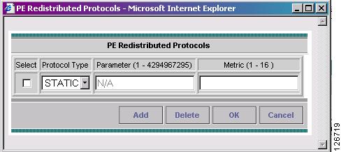
Redistribution allows routing information discovered through another routing protocol to be distributed in the update messages of the current routing protocol. With redistribution, you can reach all the points of your IP internetwork. When a RIP router receives routing information from another protocol, it updates all of its RIP neighbors with the new routing information already discovered by the protocol it imports redistribution information from.
To specify the protocols that RIP needs to import routing information to the PE:
a.
The PE Redistributed Protocol dialog box appears.
b.
The following dialog box appears (see Figure 5-14).
Figure 5-14 Selecting Protocols to Redistribute into the PE
c.
You can choose one of the following: Static, OSPF, or EIGRP.
•
When you choose Static routes for redistribution into RIP, ISC imports the static routes into the PE that is running RIP.
There are no parameters or metrics required for redistributing Static routes into the PE.
•
When you choose the OSPF protocol for redistribution into RIP, ISC imports the OSPF routes into the PE that is running RIP.
Parameter: OSPF process number
Metric: Any numeral from 1 to 16
•
When you choose the EIGRP protocol for redistribution into RIP, ISC imports the EIGRP routes into the PE that is running RIP.
Parameter: EIGRP autonomous system (AS) number
Metric: Any numeral from 1 to 16
d.
e.
f.
g.
Step 8
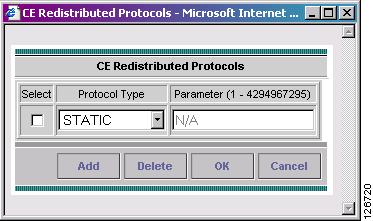
To specify the protocols that RIP needs to import routing information to the CE:
a.
The CE Redistributed Protocol dialog box appears.
b.
The following dialog box appears (see Figure 5-15).
Figure 5-15 Selecting Protocols to Redistribute into the CE
c.
You can choose one of the following protocols: Static, BGP, Connected (routes), IGRP, OSPF, EIGRP, or IS-IS.
•
When you choose Static routes for redistribution into RIP, ISC imports the static routes into the CE that is running RIP.
There are no parameters required for redistributing Static routes into the CE.
•
When you choose the BGP protocol for redistribution into RIP, ISC imports the BGP routes into the CE that is running RIP.
Parameter: BGP autonomous system (AS) number
•
When you choose the Connected routes for redistribution into RIP, ISC imports all the routes to the interfaces connected to the current router. Use the Connected option when you want to advertise a network, but you don't want to send routing updates into that network. Note that redistributing connected routes indiscriminately redistributes all connected routes into the routing domain.
Parameter: No parameter required
•
When you choose the IGRP (Interior Gateway Routing) protocol for redistribution into RIP, IP Solution Center imports the IGRP routes into the CE that is running RIP.
Parameter: IGRP autonomous system (AS) number
•
When you choose the EIGRP protocol for redistribution into RIP, ISC imports the EIGRP routes into the PE that is running RIP.
Parameter: EIGRP autonomous system (AS) number
•
When you choose the OSPF protocol for redistribution into RIP, ISC imports the OSPF routes into the CE that is running RIP.
Parameter: OSPF process number
•
When you choose the IS-IS protocol for redistribution into RIP, ISC imports the IS-IS routes into the CE that is running RIP.
Parameter: IS-IS tag number
d.
e.
f.
g.
Step 9
To complete this service policy, go to Defining the Service Policy VRF and VPN Information.
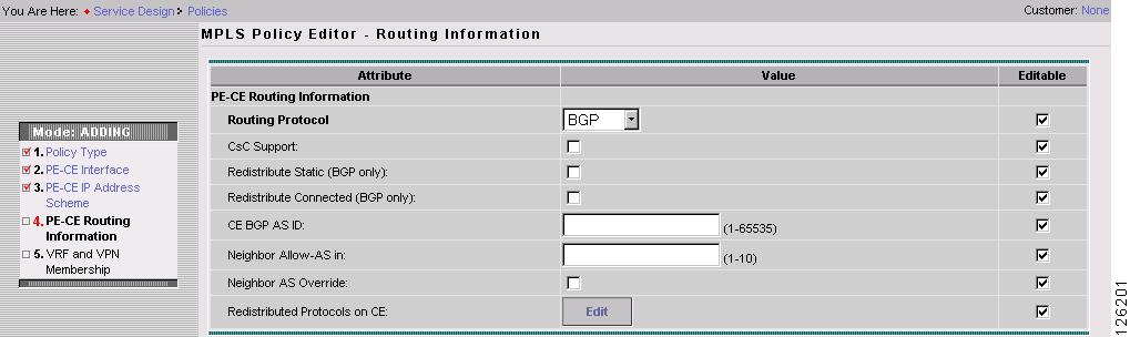
BGP Protocol Chosen
BGP (Border Gateway Protocol) operates over TCP (Transmission Control Protocol), using port 179. By using TCP, BGP is assured of reliable transport, so the BGP protocol itself lacks any form of error detection or correction (TCP performs these functions). BGP can operate between peers that are separated by several intermediate hops, even when the peers are not necessarily running the BGP protocol.
BGP operates in one of two modes: Internal BGP (iBGP) or External BGP (EBGP). The protocol uses the same packet formats and data structures in either case. IBGP is used between BGP speakers within a single autonomous system, while EBGP operates over inter-AS links.
Step 1
The BGP Routing Protocol dialog box appears (see Figure 5-16).
Figure 5-16 BGP Selected as the Routing Protocol
Step 2
Step 3
When you enable the Give only default routes to CE option, you indicate whether the site needs full routing or default routing. Full routing is when the site must know specifically which other routes are present in the VPN. Default routing is when it is sufficient to send all packets that are not specifically for your site to the VPN.
If you choose this option, ISC configures the default-info originate command on the PE router under the running protocol (for RIP, OSPF, or EIGRP). For Static, ISC configures an ip route 0.0.0.0 0.0.0.0 <out-going interface name> command on the CE router.
Step 4
If you are importing static routes into BGP, choose this check box.
Step 5
Enabling the Redistribute Connected option imports all the routes to the interfaces connected to the current router. Use the Redistribute Connected option when you want to advertise a network, but you don't want to send routing updates into that network. Note that redistributing connected routes indiscriminately redistributes all connected routes into the routing domain.
When you enable the Redistribute Connected option, the connected routes (that is, the routes to the directly connected PEs or CEs) are distributed to all the other CEs in that particular VPN. This option is meant for IBGP if the routing protocol between PE-CE is a non-BGP protocol. For example, if the routing protocol is RIP, OSPF, EIGRP, or Static, the option is meant for the router bgp that is configured on the PE for the MPLS core. On the PE router, there is one router bgp process running at all times for MPLS. This option is also for BGP.
Step 6
The autonomous number assigned here to the CE must be different from the BGP AS number for the service provider's core network.
Step 7
When you enter a Neighbor AllowAS-in value, you specify a maximum number of times (up to 10) that the service provider autonomous system (AS) number can occur in the autonomous system path.
Step 8
The AS Override feature allows the MPLS VPN service provider to run the BGP routing protocol with a customer even if the customer is using the same AS number at different sites. This feature can be used if the VPN customer uses either a private or public autonomous system number.
When you enable the Neighbor AS-Override option, you configure VPN Solutions Center to reuse the same AS number on all the VPN's sites.
Step 9
Redistributed Protocols on CE: The redistribution of routes into MP-iBGP is necessary only when the routes are learned through any means other than BGP between the PE and CE routers. This includes connected subnets and static routes. In the case of routes learned via BGP from the CE, redistribution is not required because it's performed automatically.
To specify the protocols that BGP needs to import routing information to the CE:
a.
The CE Redistributed Protocol dialog box appears.
b.
The following dialog box appears (see Figure 5-17).
Figure 5-17 Selecting Protocols to Redistribute into the CE
c.
You can choose one of the following protocols: Static, RIP, Connected (routes), IGRP, OSPF, EIGRP, or IS-IS.
•
When you choose Static routes for redistribution into BGP, ISC imports the static routes into the CE that is running BGP.
Parameter: No parameter required
•
When you choose the RIP protocol for redistribution into BGP, Cisco ISC imports the RIP routes into the CE that is running BGP.
Parameter: No parameter required
•
When you choose the Connected routes for redistribution into BGP, ISC imports all the routes to the interfaces connected to the current router. Use the Connected option when you want to advertise a network, but you don't want to send routing updates into that network. Note that redistributing connected routes indiscriminately redistributes all connected routes into the routing domain.
Parameter: No parameter required
•
When you choose the IGRP (Interior Gateway Routing) protocol for redistribution into BGP, IP Solution Center imports the IGRP routes into the CE that is running BGP.
Parameter: IGRP autonomous system (AS) number
•
When you choose the EIGRP protocol for redistribution into BGP, ISC imports the EIGRP routes into the CE that is running BGP.
Parameter: EIGRP autonomous system (AS) number
•
When you choose the OSPF protocol for redistribution into BGP, ISC imports the OSPF routes into the CE that is running BGP.
Parameter: OSPF process number
•
When you choose the IS-IS protocol for redistribution into BGP, ISC imports the IS-IS routes into the CE that is running BGP.
Parameter: IS-IS tag number
d.
e.
f.
g.
Step 10
To complete this service policy, go to Defining the Service Policy VRF and VPN Information.
OSPF Protocol Chosen
The MPLS VPN backbone is not a genuine OSPF area 0 backbone. No adjacencies are formed between PE routers—only between PEs and CEs. MP-iBGP is used between PEs, and all OSPF routes are translated into VPN IPv4 routes. Thus, redistributing routes into BGP does not cause these routes to become external OSPF routes when advertised to other member sites of the same VPN.
Step 1
The OSPF Routing Protocol dialog box appears (see Figure 5-18).
Figure 5-18 OSPF Selected as the Routing Protocol
Step 2
Step 3
When you enable the Give only default routes to CE option, you indicate whether the site needs full routing or default routing. Full routing is when the site must know specifically which other routes are present in the VPN. Default routing is when it is sufficient to send all packets that are not specifically for your site to the VPN.
If you choose this option, ISC configures the default-info originate command on the PE router under the running protocol RIP or EIGRP and the default-info originate always command on the PE router under the running protocol OSPF for Static and configures an ip route 0.0.0.0 0.0.0.0 <out-going interface name> command on the CE router.
Step 4
If you are importing static routes into OSPF, choose this check box.
Step 5
Enabling the Redistribute Connected option imports all the routes to the interfaces connected to the current router. Use the Redistribute Connected option when you want to advertise a network, but you don't want to send routing updates into that network. Note that redistributing connected routes indiscriminately redistributes all connected routes into the routing domain.
This option is meant for IBGP if the routing protocol between PE-CE is a non-BGP protocol. For example, if the routing protocol is RIP, OSPF, EIGRP, or Static, the option is meant for the router bgp that is configured on the PE for the MPLS core. On the PE router, there is one router bgp process running at all times for MPLS. This option is also for BGP.
Step 6
The OSPF process ID is a unique value assigned for each OSPF routing process within a single router—this process ID is internal to the PE only.
Step 7
The OSPF process ID is a unique value assigned for each OSPF routing process within a single router—this process ID is internal to the CE only. You can enter this number either as any decimal number from 1 to 65535, or a number in dotted decimal notation.
Step 8
You can enter the OSPF area number for the PE either as any decimal number in the range specified, or a number in dotted decimal notation.
Step 9
Note
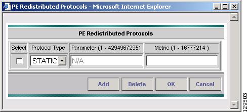
To specify the protocols that OSPF needs to import to the PE, follow these steps:
a.
The PE Redistributed Protocol dialog box appears.
b.
The following dialog box appears (see Figure 5-19).
Figure 5-19 Selecting Protocols to Redistribute into the PE
c.
You can choose one of the following: Static, EIGRP, or RIP.
•
When you choose Static routes for redistribution into OSPF, ISC imports the static routes into the PE that is running OSPF.
There are no parameters or metrics required for redistributing Static routes into the PE.
•
When you choose the EIGRP protocol for redistribution into OSPF, ISC imports the EIGRP routes into the PE that is running OSPF.
Parameter: EIGRP autonomous system (AS) number
Metric: Any numeral from 1 to 16777214
•
When you choose the RIP protocol for redistribution into OSPF, ISC imports the RIP routes into the PE that is running OSPF.
Parameter: No parameter required
Metric: Any numeral from 1 to 16777214
d.
e.
f.
g.
Step 10
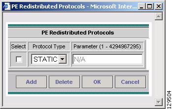
Redistribute Protocols on CE: To specify the protocols that OSPF needs to import routing information to the CE, follow these steps:
a.
The CE Redistributed Protocol dialog box appears.
b.
The following dialog box appears (see Figure 5-20).
Figure 5-20 Selecting Protocols to Redistribute into the CE
c.
You can choose one of the following protocols: Static, RIP, BGP, Connected (routes), IGRP, EIGRP, or IS-IS.
•
When you choose Static routes for redistribution into OSPF, ISC imports the static routes into the CE that is running OSPF.
There are no parameters required for redistributing Static routes into the CE.
•
When you choose the RIP protocol for redistribution into OSPF, ISC imports the RIP routes into the CE that is running OSPF.
Parameter: No parameter required
•
When you choose the BGP protocol for redistribution into OSPF, ISC imports the BGP routes into the CE that is running OSPF.
Parameter: BGP autonomous system (AS) number
•
When you choose the Connected routes for redistribution into OSPF, ISC imports all the routes to the interfaces connected to the current router. Use the Connected option when you want to advertise a network, but you don't want to send routing updates into that network. Note that redistributing connected routes indiscriminately redistributes all connected routes into the routing domain.
Parameter: No parameter required
•
When you choose the IGRP (Interior Gateway Routing) protocol for redistribution into OSPF, IP Solution Center imports the IGRP routes into the CE that is running OSPF.
Parameter: IGRP autonomous system (AS) number
•
When you choose the EIGRP protocol for redistribution into OSPF, ISC imports the EIGRP routes into the CE that is running OSPF.
Parameter: EIGRP autonomous system (AS) number
•
When you choose the IS-IS protocol for redistribution into OSPF, ISC imports the IS-IS routes into the CE that is running OSPF.
Parameter: IS-IS tag number
d.
e.
f.
g.
Step 11
To complete this service policy, go to Defining the Service Policy VRF and VPN Information.
EIGRP Protocol Chosen
Enhanced IGRP (EIGRP) is a hybrid routing protocol that discovers a network like a distance vector protocol (namely IGRP), but maintains a topological database for rapid reconvergence. EIGRP supports variable length subnet masks and discontinuous subnets. When configured for IP, it automatically redistributes routes with IGRP processes defined in the same autonomous system. By default, EIGRP auto-summarizes subnets at the classful network boundaries.
EIGRP performs the same metric accumulation as IGRP. However, if you examine the metric calculation between IGRP and EIGRP, you will see that the EIGRP value is much greater. If you divide the EIGRP metric by 256, you get the same IGRP metric value.
EIGRP allows all routers involved in a topology change to synchronize at the same time. Routers that are not affected by topology changes are not involved in the recomputation. The result is very fast convergence time.
Step 1
The EIGRP Routing Protocol dialog box appears (see Figure 5-21).
Figure 5-21 EIGRP Selected as the Routing Protocol
Step 2
Step 3
When you enable the Redistribute Static option for BGP, the software imports the static routes into the core network (running BGP).
Step 4
When you enable the Redistribute Connected option, the connected routes (that is, the routes to the directly connected PEs or CEs) are distributed to all the other CEs in that particular VPN. This option is meant for IBGP if the routing protocol between PE-CE is a non-BGP protocol. For example, if the routing protocol is RIP, OSPF, EIGRP, or Static, the option is meant for the router bgp that is configured on the PE for the MPLS core. On the PE router, there is one router bgp process running at all times for MPLS. This option is also for BGP.
Note
Step 5
Step 6
Step 7
EIGRP Metrics
EIGRP uses metrics in the same way as IGRP. Each route in the route table has an associated metric. EIGRP uses a composite metric much like IGRP, except that it is modified by a multiplier of 256. Bandwidth, Delay, Load, Reliability, and MTU are the submetrics. Like IGRP, EIGRP chooses a route based primarily on bandwidth and delay, or the composite metric with the lowest numerical value. When EIGRP calculates this metric for a route, it calls it the feasible distance to the route. EIGRP calculates a feasible distance to all routes in the network.
Bandwidth Metric: Bandwidth is expressed in units of Kilobits. It must be statically configured to accurately represent the interfaces that EIGRP is running on. For example, the default bandwidth of a 56-kbps interface and a T1 interface is 1,544 kbps.
Delay Metric: Delay is expressed in microseconds. It, too, must be statically configured to accurately represent the interface that EIGRP is running on. The delay on an interface can be adjusted with the delay time_in_microseconds interface subcommand.
Reliability Metric: Reliability is a dynamic number in the range of 1 to 255, where 255 is a 100 percent reliable link and 1 is an unreliable link.
Loading Metric: Load is the number in the range of 1 to 255 that shows the output load of an interface. This value is dynamic and can be viewed using the show interfaces command. A value of 1 indicates a minimally loaded link, whereas 255 indicates a link loaded 100 percent.
MTU Metric: The maximum transmission unit (MTU) is the recorded smallest MTU value in the path, usually 1500.
Note
Step 8
When configured for IP, it automatically redistributes routes with IGRP processes defined in the same autonomous system. By default, EIGRP auto-summarizes subnets at the classful network boundaries.
To specify the protocols that EIGRP needs to import to the PE:
a.
The PE Redistributed Protocol dialog box appears.
b.
The following dialog box appears (see Figure 5-22).
Figure 5-22 Selecting Protocols to Redistribute into the PE
c.
You can choose one of the following: Static, RIP, or OSPF.
•
When you choose Static routes for redistribution into EIGRP, ISC imports the static routes into the PE that is running OSPF.
There are no parameters or metrics required for redistributing Static routes into the PE.
•
When you choose the RIP protocol for redistribution into EIGRP, ISC imports the RIP routes into the PE that is running EIGRP.
Parameter: No parameter required
Metric: Any numeral from 1 to 16777214
•
When you choose the OSPF protocol for redistribution into EIGRP, ISC imports the OSPF routes into the PE that is running EIGRP.
Parameter: OSPF process number
Metric: Any numeral from 1 to 16
d.
e.
f.
g.
Step 9
To specify the protocols that EIGRP needs to import routing information to the CE:
a.
The CE Redistributed Protocol dialog box appears.
b.
The following dialog box appears (see Figure 5-23):
Figure 5-23 Selecting Protocols to Redistribute into the CE
c.
You can choose one of the following protocols: Static, BGP, Connected (routes), IGRP, RIP, OSPF, or IS-IS.
•
When you choose Static routes for redistribution into EIGRP, ISC imports the static routes into the CE that is running OSPF.
There are no parameters required for redistributing Static routes into the CE.
•
When you choose the BGP protocol for redistribution into EIGRP, ISC imports the BGP routes into the CE that is running OSPF.
Parameter: BGP autonomous system (AS) number
•
When you choose the Connected routes for redistribution into EIGRP, ISC imports all the routes to the interfaces connected to the current router. Use the Connected option when you want to advertise a network, but you don't want to send routing updates into that network. Note that redistributing connected routes indiscriminately redistributes all connected routes into the routing domain.
When you enable the Redistribute Connected option, the connected routes (that is, the routes to the directly connected PEs or CEs) are distributed to all the other CEs in that particular VPN. This option is meant for IBGP if the routing protocol between PE-CE is a non-BGP protocol. For example, if the routing protocol is RIP, OSPF, EIGRP, or Static, the option is meant for the router bgp that is configured on the PE for the MPLS core. On the PE router, there is one router bgp process running at all times for MPLS. This option is also for BGP.
Parameter: No parameter required
•
When you choose the IGRP (Interior Gateway Routing) protocol for redistribution into EIGRP, IP Solution Center imports the IGRP routes into the CE that is running EIGRP.
Parameter: IGRP autonomous system (AS) number
•
When you choose the RIP protocol for redistribution into EIGRP, Cisco ISC imports the RIP routes into the CE that is running EIGRP.
Parameter: No parameter required
•
When you choose the OSPF protocol for redistribution into EIGRP, ISC imports the OSPF routes into the CE that is running EIGRP.
Parameter: OSPF process number
•
When you choose the IS-IS protocol for redistribution into EIGRP, ISC imports the IS-IS routes into the CE that is running EIGRP.
Parameter: IS-IS tag number
d.
e.
f.
g.
Step 10
To complete this service policy, go to Defining the Service Policy VRF and VPN Information.
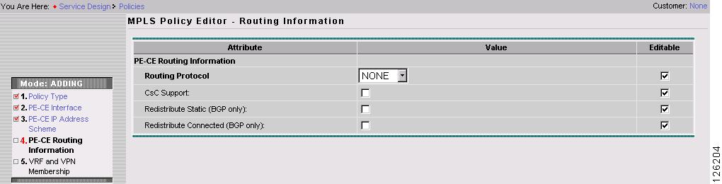
None Chosen: Cable Services
When operating a cable link, the link does not run a routing protocol. The None option in the service policy routing protocol dialog box is provided to allow for configuring a service over a cable link without having to unnecessarily specify a routing protocol.
Step 1
The following dialog box appears (see Figure 5-24):
Figure 5-24 No Routing Protocol Selected
Step 2
Step 3
Step 4
When you enable the Redistribute Connected option, the connected routes (that is, the routes to the directly connected PEs or CEs) are distributed to all the other CEs in that particular VPN. This option is meant for IBGP if the routing protocol between PE-CE is a non-BGP protocol. For example, if the routing protocol is RIP, OSPF, EIGRP, or Static, the option is meant for the router bgp that is configured on the PE for the MPLS core. On the PE router, there is one router bgp process running at all times for MPLS. This option is also for BGP.
Step 5
Defining an MVRFCE PE-CE Service Policy
To define an MVRFCE PE-CE Service Policy, follow these steps:
Step 1
Step 2
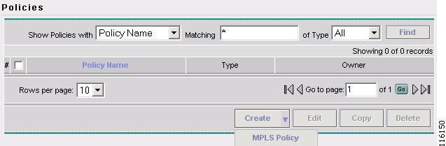
The Policies window appears, as shown in Figure 5-25.
Figure 5-25 Policies
Step 3
The MPLS Policy Editor - Policy Type window appears, as shown in Figure 5-26.
Figure 5-26 MPLS Policy Editor - Policy Type
Step 4
Step 5
Step 6
Step 7
Step 8
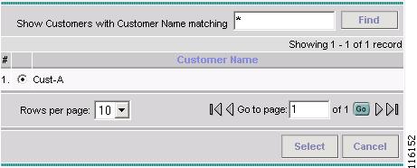
The Customer for MPLS Policy ownership window appears, as shown in Figure 5-27.
Figure 5-27 Customer for MPLS Policy
Step 9
Step 10
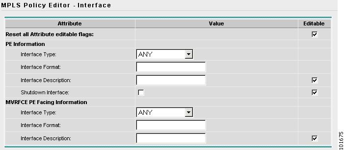
The MPLS Policy Editor - PE Interface window appears, as shown in Figure 5-28.
Figure 5-28 The MPLS Policy Editor - PE Interface
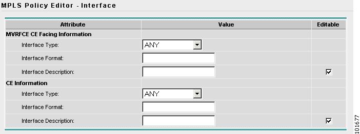
Step 11
The MPLS Policy Editor - CE Interface window appears, as shown in Figure 5-29.
Figure 5-29 The MPLS Policy Editor - CE Interface
Step 12
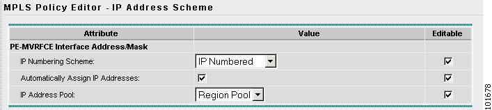
Note
The MPLS Policy Editor - PE IP Address Scheme window appears, as shown in Figure 5-30.
Figure 5-30 The MPLS Policy Editor - PE IP Address Scheme
Step 13
The IP Address Pool appears with the Region Pool in the window.
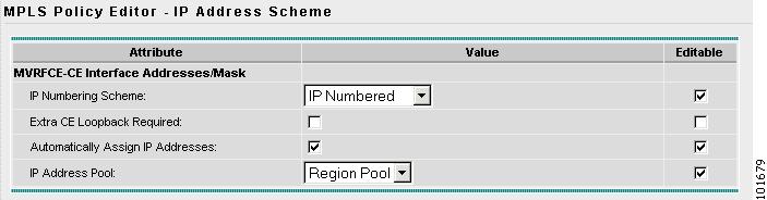
Step 14
The MPLS Policy Editor - CE IP Address Scheme window appears, as shown in Figure 5-30.
Figure 5-31 The MPLS Policy Editor - CE IP Address Scheme
Step 15
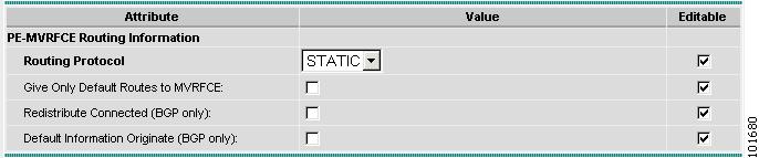
Step 16
The MPLS Policy Editor - PE Routing Information window appears, as shown in Figure 5-32.
Figure 5-32 The MPLS Policy Editor - PE Routing Information
Step 17
The MPLS Policy Editor - CE Routing Information window appears, as shown in Figure 5-33.
Figure 5-33 The MPLS Policy Editor - CE Routing Information
Step 18
Note
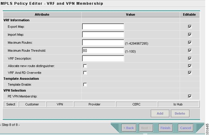
The MPLS Policy Editor - VRF and VPN Membership window appears, as shown in Figure 5-34.
Figure 5-34 The MPLS Policy Editor - VRF and VPN Membership
Step 19
Note
Step 20
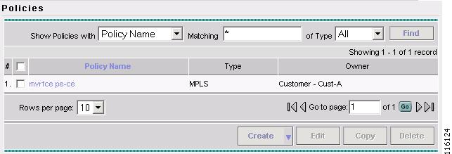
The Policies window reappears, as shown in Figure 5-35.
Figure 5-35 Policies
The MVRFCE PE-CE Service Policy is complete.
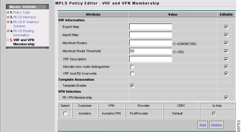
Defining the Service Policy VRF and VPN Information
When you are finished defining the routing protocol(s) for this service policy, you must then specify the VRF information.
The MPLS Policy VRF and VPN Membership dialog box appears (see Figure 5-36).
Figure 5-36 Specifying the VRF Information
To specify the VRF and VPN information for this service policy:
Step 1
The name of the export route map you enter here must be the name of an existing export route map on the PE.
Note
When you use the ISC software to define a management VPN, ISC automatically generates an export route map for the management VPN. Because the Cisco IOS supports only one export route map per VRF and that route map is reserved for the management VPN, the Export Map field is not available if the VRF is part of the management VPN.
An export route map does not apply a filter; it can be used to override the default set of route targets associated with a route.
Step 2
The name of the import route map you enter here must be the name of an existing import route map on the PE.
Note
An import route map does apply a filter. Therefore, if you want to exclude a particular route from the VRF on this PE, you can either set an export route map on the sending router to make sure it does not have any route targets that can be imported into the current VRF, or create an import route map on the PE to exclude the route.
Step 3
Step 4
Step 5
Step 6
When Allocate new route distinguisher is enabled, create a new VRF if there is no matching VRF configuration on that PE; otherwise, refuse it.
When Allocate new route distinguisher is disabled, find the first matching VRF configuration across the entire range of PEs, regardless of the PE. If this VRF is found on the PE being configured, reuse it. If it isn't found on the PE, create it.
Note
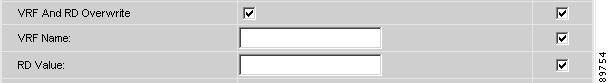
ISC automatically sets the route target (RT) and RD values, but you can assign your own values by checking the VRF and RD check box instead.
Step 7
Caution
Figure 5-37 No Routing Protocol Selected
a.
b.
Step 8
When you enable the Template Enable option, the next dialog box that appears will let the service operator choose the templates to the associated with the MPLS link.
Step 9
The PE VPN Membership information includes the customer name, VPN name, service provider name, CE routing community name, and whether the CERC type is a hub-and-spoke CERC or a fully meshed CERC.
If the Is Hub check box is checked, it indicates that the CERC type is hub-and-spoke.
Using the Add and Delete buttons, you can add a VPN to this list or delete a VPN from this list.
Step 10
Now that you have defined a service policy for an MPLS PE-to-CE service, the service operator can now use this policy to create and deploy a service request for a PE-CE link. For details, see "MPLS VPN Service Requests."