-
Cisco IOS Software Configuration Guide for Cisco Aironet 1300 Series Outdoor Access Point/Bridge 12.3(7)JA
-
Preface
-
Overview
-
Configuring the Access Point/Bridge for the
-
Using the Web-Browser Interface
-
Using the Command-Line Interface
-
Administering the Access Point/Bridge
-
Configuring Radio Settings
-
Configuring Multiple SSIDs
-
Configuring Spanning Tree Protocol
-
Configuring Cipher Suites and WEP
-
Configuring Authentication Types
-
Configuring WDS, Fast Secure Roaming, Radio Management, and Wireless Intrusion Detection Services
-
Configuring RADIUS and TACACS+ Servers
-
Configuring VLANs
-
Configuring QoS
-
Configuring Filters
-
Configuring CDP
-
Configuring SNMP
-
Managing Firmware and Configurations
-
Configuring System Message Logging
-
Configuring Repeater and Standby Access Points and Workgroup Bridge Mode
-
Troubleshooting
-
Protocol Filters
-
Supported MIBs
-
Error and Event Messages
-
Glossary
-
 Feedback
Table Of Contents
Checking Basic Configuration Settings
Resetting the Access Point/Bridge to the Default Configuration
Using the Web-Browser Interface
Corrupt IOS Configuration or Lost Password Procedure
Reloading the Access Point/Bridge Image
Obtaining the Access Point/Bridge Image File
Obtaining the TFTP Server Software
Troubleshooting
This chapter provides troubleshooting procedures for basic problems with the access point/bridge. For the most up-to-date, detailed troubleshooting information, refer to the Cisco TAC website at the following URL (select Hardware Support > Wireless Devices):
http://www.cisco.com/cisco/web/support/index.html
Sections in this chapter include:
•
Checking Basic Configuration Settings
•
•
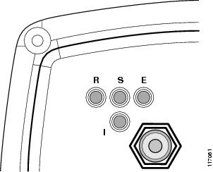
Checking the LEDs
If your access point/bridge is not associating with a remote bridge or access point, check the four LEDs on the back panel. You can use them to quickly assess the unit's status. For information on using the LEDs during the installation and alignment of the access point/bridge antenna, refer to the Cisco Aironet 1300 Series Outdoor Access Point/Bridge Mounting Instructions that shipped with your access point/bridge.
Figure 21-1 shows the access point/bridge LEDs.
Figure 21-1 LEDs
Normal Mode LED Indications
During access point/bridge operation the LEDs provide status information as shown in Table 21-1.
Table 21-1 LED Indications
LED
LED
LED
LED
Off
—
—
—
Ethernet link is down or disabled.
Blinking green
—
—
—
Transmitting and receiving Ethernet packets.
Blinking amber
—
—
—
Transmitting and receiving Ethernet errors.
amber
—
—
—
Firmware error—disconnect and reconnect the power injector power jack. If the problem continues, contact technical support for assistance.
—
Blinking green
—
—
Root bridge mode—no remote bridges are associated.
Non-root bridge mode—not associated to the root bridge.
If all bridges are powered up, this could be caused by incorrect SSID and security settings or improper antenna alignment. You should check the SSID and security settings of all bridges and verify antenna alignment.If the problem continues, contact technical support for assistance.
—
Green
—
—
Root mode—associated to at least one remote bridge.
Non-root mode—associated to the root bridge.
This is normal operation.—
Blinking amber
—
—
General warning—disconnect and reconnect the power injector power jack. If the problem continues, contact technical support for assistance.
—
Amber
—
—
Loading firmware.
Red
Amber
Red
—
Loading Firmware error—disconnect and reconnect the power injector power. If the problem continues, contact technical support for assistance.
—
—
Off
—
Normal operation.
—
—
Blinking green
—
Transmitting and receiving radio packets—normal operation.
—
—
Blinking amber
—
Maximum retries or buffer full occurred on the radio interface—disconnect and reconnect the power injector power jack. If the problem continues, contact technical support for assistance.
—
—
Amber
—
Radio firmware error—disconnect and reconnect power injector power.If the problem continues, contact technical support for assistance.
—
—
—
Amber blinking
Not associated (non-root mode). The access point/bridge attempts to associate with a root bridge for 60 seconds1 .
—
—
—
Amber
Associated (non-root mode).
—
—
—
Green blinking
Not associated (root mode). The access point/bridge attempts to associate with a non-root bridge indefinitely.
—
—
—
Green
Associated (root mode).
—
—
—
Red
Overcurrent or overvoltage error—disconnect power to the power injector, check all coax cable connections, wait approximately 1 minute, and reconnect power. If error continues, contact technical support.
1 Preconfigured bridges search indefinitely.
The access point/bridge uses a blinking code to identify various error conditions. The code sequence uses a two-digit diagnostic code that starts with a long pause to delimit the code, followed by the LED flashing red to count out the first digit, then a short pause, followed by the LED flashing red to count out the second digit.
The LED blinking error codes are described in Table 21-2.
Power Injector
When the power injector is powered up, it applies 48-VDC to the dual-coax cables to the access point/bridge.
When power is applied to the access point/bridge, the unit activates the bootloader and begins the POST operations. The access point/bridge begins to load the IOS image when the Post operations are successfully completed. Upon successfully loading the IOS image, the unit initializes and tests the radio.
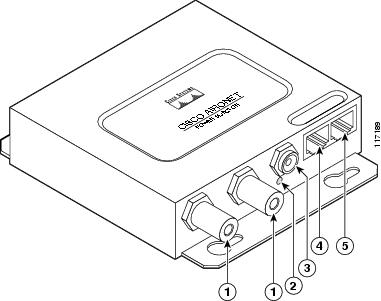
The power injector LED is shown in Figure 21-2.
Figure 21-2 Power Injector
Dual-coax Ethernet ports (F-Type connectors)
Ethernet LAN port (RJ-45 connector)
Power LED
Console serial port (RJ-45 connector)
Power jack
The power injector is available in two models:
•
–
–
•
–
–
Checking Power
You can verify the availability of power to the access point/bridge by checking the power injector LED (see Figure 21-2):
•
–
–
Note
–
Checking Basic Configuration Settings
Mismatched basic settings are the most common causes of lost wireless connectivity. If the access point/bridge does not associate with a remote bridge, access point, or client device, check the following areas.
SSID
Wireless clients attempting to associate with the bridge must use the same SSID as the bridge. If a client device's SSID does not match the SSID of an bridge in radio range, the client device will not associate.
Note
WEP Keys
The WEP key you use to transmit data must be set up exactly the same on the access point/bridge and any wireless devices with which it associates. For example, if you set WEP Key 3 on your client adapter to 0987654321 and select it as the transmit key, you must set WEP Key 3 on the access point/bridge to exactly the same value. The access point/bridge does not need to use Key 3 as its transmit key, however.
Refer to Chapter 9 "Configuring Cipher Suites and WEP," for instructions on setting the wireless device's WEP keys.
Security Settings
Wireless clients attempting to authenticate with the bridge must support the same security options configured in the access point/bridge, such as EAP or LEAP, MAC address authentication, Message Integrity Check (MIC), WEP key hashing, and 802.1X protocol versions.
If a wireless client is unable to authenticate with the access point/bridge, contact the system administrator for proper security settings in the client adapter and for the client adapter driver and firmware versions that are compatible with the access point/bridge settings.
Note
Antenna Alignment
If your non-root bridges or non-root access points are unable to associate to your root bridge or root access point, you should verify the basic configuration settings on all bridges or access points before attempting to verify antenna alignment (Chapter 2 "Configuring the Access Point/Bridge for the First Time." If your basic configuration settings are correct, you can verify antenna alignment by using the Install mode RSSI LED indications. For additional information, refer to the Cisco Aironet 1300 Series Outdoor Access Point/Bridge Mounting Instructions that shipped with your access point/bridge.
Note
Resetting the Access Point/Bridge to the Default Configuration
You can use the web-browser interface or the CLI to reset the access point/bridge to a factory default configuration.
Note
Using the Web-Browser Interface
Follow the steps below to delete the current configuration and return all access point/bridge settings to the factory defaults using the Web-browser interface.
Step 1
Step 2
Step 3
Step 4
Step 5
Step 6
Step 7
a.
b.
Step 8
Using the CLI
From the privileged EXEC mode, you can reset the access point/bridge configuration to factory default values using the CLI by following these steps:
Step 1
Step 2
Step 3
Step 4
Caution
Step 5
The access point/bridge is configured with the factory default values including the IP address (set to receive an IP address using DHCP). To obtain the unit's new IP address, you can use the show interface bvi1 CLI command. If the unit does not receive an IP address from a DHCP server, the access point/bridge IP address is 10.0.0.1.
Corrupt IOS Configuration or Lost Password Procedure
This section describes the procedure for resetting the access point/bridge to its default settings in the unlikely event that the operating system is corrupt or if you have misplaced the configuration login and password. Because the access point/bridge does not have a mode switch, you must use the console port to perform this operation. Follow these steps to reset the unit to its default settings:
Step 1
Step 2
Step 3
Note
Loading "flash:/c1310-k9kw-7mx.v122_15_ja.200040314-k9w7-mx.v122_15_ja.20040314"...####################################################################################################################################################################################################################################################Messages similar to those below appear:
Error loading "flash:/c1310-k9kw-7mx.v122_15_ja.200040314-k9w7-mx.v122_15_ja.20040314"Interrupt within 5 seconds to abort boot process.Boot process terminated.The system is unable to boot automatically. The BOOT environment variable needs to be set to a bootable image.C1310 Boot Loader (C1310-BOOT-M), Version 12.2 [BLD-v122_15-ja_throttle.20040314 100]ap:Step 4
ap: dir flash:Directory of flash:/2 -rwx 0 <date> env_vars5 drwx 384 <date> C1310-k9w7-mx.v133_15_JA.200403143 -rwx 1128 <date> config.txt4 -rwx 5 <date> private-config3693568 bytes available (4047872 bytes used)ap:Step 5
Note
Note
Reloading the Access Point/Bridge Image
If your access point/bridge has a firmware failure, you must reload the complete image file using the Web-browser interface or by using the console serial port. You can use the browser interface if the access point/bridge firmware is operational. However, you can use the console serial port when the access point/bridge has a corrupt image.
Web-Browser Interface
You can also use the Web-browser interface to reload the access point/bridge image file. The Web-browser interface supports loading the image file using HTTP or TFTP interfaces.
Note
Browser HTTP Interface
The HTTP interface enables you to browse to the access point/bridge image file on your PC and download the image to the unit. Follow the instructions below to use the HTTP interface:
Step 1
Step 2
Step 3
Step 4
Step 5
Step 6
Step 7
Step 8
For additional information, click the Help icon on the Software Upgrade screen.
Browser TFTP Interface
The TFTP interface enables you to use a TFTP server on a network device to load the access point/bridge image file. Follow the instructions below to use a TFTP server:
Step 1
Step 2
Step 3
Step 4
Step 5
Step 6
Step 7
Step 8
Step 9
Step 10
For additional information click the Help icon on the Software Upgrade screen.
Using the CLI
Follow the steps below to reload the access point image using the CLI. When the access point begins to boot, you interrupt the boot process and use boot loader commands to load an image from a TFTP server to replace the image in the access point.
Note
Step 1
Step 2
Step 3
Loading "flash:/c1310-k9w7-mx.v122_13_ja.20031010/c1310-k9w7-mx.v122_13_ja.20031010"
...###########################################################################
################################################################################
################################################################################
####################
Note
Step 4
Note
Your entries might look like this example:
ap: set IP_ADDR 192.168.133.160ap: set NETMASK 255.255.255.0ap: set DEFAULT_ROUTER 192.168.133.1Step 5
ap: tftp_initStep 6
•
•
•
•
•
Your entry might look like this example:
ap: tar -xtract tftp://192.168.130.222/images/c1310-k9w7-tar.122_15.JA1 flash:Step 7
--MORE--. Press the spacebar to continue.extracting info (229 bytes)c1310-k9w7-mx.122-15.JA1/ (directory) 0 (bytes)c1310-k9w7-mx.122-15.JA1/html/ (directory) 0 (bytes)c1310-k9w7-mx.122-15.JA1/html/level1/ (directory) 0 (bytes)extracting c1310-k9w7-mx.122-15.JA1/html/level1/appsui.js (558 bytes)extracting c1310-k9w7-mx.122-15.JA1/html/level1/back.htm (205 bytes)extracting c1310-k9w7-mx.122-15.JA1/html/level1/cookies.js (5027 bytes).extracting c1310-k9w7-mx.122-15.JA1/html/level1/forms.js (15704 bytes)...extracting c1310-k9w7-mx.122-15.JA1/html/level1/sitewide.js (14621 bytes)...extracting c1310-k9w7-mx.122-15.JA1/html/level1/config.js (2554 bytes)extracting c1310-k9w7-mx.122-15.JA1/html/level1/stylesheet.css (3215 bytes)c1310-k9w7-mx.122-15.JA1/html/level1/images/ (directory) 0 (bytes)extracting c1310-k9w7-mx.122-15.JA1/html/level1/images/ap_title_appname.gif (1422 bytes)extracting c1310-k9w7-mx.122-15.JA1/html/level1/images/apps_button_1st.gif (1171 bytes)extracting c1310-k9w7-mx.122-15.JA1/html/level1/images/apps_button_cbottom.gif (318 bytes)extracting c1310-k9w7-mx.122-15.JA1/html/level1/images/apps_button_current.gif (348 bytes)extracting c1310-k9w7-mx.122-15.JA1/html/level1/images/apps_button_last.gif (386 bytes)extracting c1310-k9w7-mx.122-15.JA1/html/level1/images/apps_button_last_filler.gif (327 bytes)extracting c1310-k9w7-mx.122-15.JA1/html/level1/images/apps_button_last_flat.gif (318 bytes)extracting c1310-k9w7-mx.122-15.JA1/html/level1/images/apps_button_nth.gif (1177 bytes)extracting c1310-k9w7-mx.122-15.JA1/html/level1/images/apps_leftnav_dkgreen.gif (869 bytes)-- MORE --If you do not press the spacebar to continue, the process eventually times out and the access point stops inflating the image.
Step 8
ap: set BOOT flash:/c1310-k9w7-mx.122-15.JA1/c1310-k9w7-mx.122-15.JA1Step 9
ap: setBOOT=flash:/c1310-k9w7-mx.122-15.JA1/c1310-k9w7-mx.122-15.JA1DEFAULT_ROUTER=192.168.133.1IP_ADDR=192.168.133.160NETMASK=255.255.255.0Step 10
ap: boot
Obtaining the Access Point/Bridge Image File
You can obtain the access point/bridge image file from the Cisco.com software center by following these steps:
Step 1
http://www.cisco.com/cisco/software/navigator.html
Step 2
Step 3
Step 4
Step 5
Step 6
Step 7
Step 8
Obtaining the TFTP Server Software
You can download TFTP server software from several web sites. Cisco recommends the shareware TFTP utility available at this URL:
Follow the instructions on the website for installing and using the utility.