-
Cisco IOS Software Configuration Guide for Cisco Aironet 1300 Series Outdoor Access Point/Bridge 12.3(7)JA
-
Preface
-
Overview
-
Configuring the Access Point/Bridge for the
-
Using the Web-Browser Interface
-
Using the Command-Line Interface
-
Administering the Access Point/Bridge
-
Configuring Radio Settings
-
Configuring Multiple SSIDs
-
Configuring Spanning Tree Protocol
-
Configuring Cipher Suites and WEP
-
Configuring Authentication Types
-
Configuring WDS, Fast Secure Roaming, Radio Management, and Wireless Intrusion Detection Services
-
Configuring RADIUS and TACACS+ Servers
-
Configuring VLANs
-
Configuring QoS
-
Configuring Filters
-
Configuring CDP
-
Configuring SNMP
-
Managing Firmware and Configurations
-
Configuring System Message Logging
-
Configuring Repeater and Standby Access Points and Workgroup Bridge Mode
-
Troubleshooting
-
Protocol Filters
-
Supported MIBs
-
Error and Event Messages
-
Glossary
-
 Feedback
Table Of Contents
Administering the Access Point/Bridge
Preventing Unauthorized Access to Your Access Point/Bridge
Protecting Access to Privileged EXEC Commands
Default Password and Privilege Level Configuration
Setting or Changing a Static Enable Password
Protecting Enable and Enable Secret Passwords with Encryption
Configuring Username and Password Pairs
Configuring Multiple Privilege Levels
Setting the Privilege Level for a Command
Logging Into and Exiting a Privilege Level
Controlling Access Point/Bridge Access with RADIUS
Configuring RADIUS Login Authentication
Configuring RADIUS Authorization for User Privileged Access and Network Services
Displaying the RADIUS Configuration
Controlling Access Point/Bridge Access with TACACS+
Configuring TACACS+ Login Authentication
Configuring TACACS+ Authorization for Privileged EXEC Access and Network Services
Displaying the TACACS+ Configuration
Configuring Ethernet Speed and Duplex Settings
Configuring the Access Point/Bridge for Local Authentication and Authorization
Configuring the Authentication Cache and Profile
Configuring the Access Point/Bridge to Provide DHCP Service
Monitoring and Maintaining the DHCP Server Access Point
Configuring the Access Point for Secure Shell
Configuring Client ARP Caching
Understanding Client ARP Caching
Managing the System Time and Date
Understanding the System Clock
Understanding Network Time Protocol
Configuring NTP Authentication
Configuring NTP Broadcast Service
Configuring NTP Access Restrictions
Configuring the Source IP Address for NTP Packets
Displaying the NTP Configuration
Configuring Time and Date Manually
Displaying the Time and Date Configuration
Configuring Summer Time (Daylight Saving Time)
Configuring a System Name and Prompt
Default System Name and Prompt Configuration
Displaying the DNS Configuration
Configuring a Message-of-the-Day Login Banner
Administering the Access Point/Bridge
This chapter describes how to administer your access point/bridge. This chapter contains these sections:
•
Preventing Unauthorized Access to Your Access Point/Bridge
•
•
•
•
•
•
•
•
•
•
Preventing Unauthorized Access to Your Access Point/Bridge
You can prevent unauthorized users from reconfiguring your access point/bridge and viewing configuration information. Typically, you want network administrators to have access to the access point/bridge while you restrict access to users who connect through a terminal or workstation from within the local network.
To prevent unauthorized access to your access point/bridge, you should configure one of these security features:
•
Note
Usernames and passwords are case-sensitive.•
Protecting Access to Privileged EXEC Commands
A simple way of providing terminal access control in your network is to use passwords and assign privilege levels. Password protection restricts access to a network or network device. Privilege levels define what commands users can issue after they have logged into a network device.
Note
This section describes how to control access to the configuration file and privileged EXEC commands. It contains this configuration information:
•
•
•
•
•
Default Password and Privilege Level Configuration
Table 5-1 shows the default password and privilege level configuration.
Setting or Changing a Static Enable Password
The enable password controls access to the privileged EXEC mode.
Note
Beginning in privileged EXEC mode, follow these steps to set or change a static enable password:
This example shows how to change the enable password to l1u2c3k4y5. The password is not encrypted and provides access to level 15 (traditional privileged EXEC mode access):
bridge(config)# enable password l1u2c3k4y5Protecting Enable and Enable Secret Passwords with Encryption
To provide an additional layer of security, particularly for passwords that cross the network or that are stored on a Trivial File Transfer Protocol (TFTP) server, you can use either the enable password or enable secret global configuration commands. Both commands accomplish the same thing; that is, you can establish an encrypted password that users must enter to access privileged EXEC mode (the default) or any privilege level you specify.
We recommend that you use the enable secret command because it uses an improved encryption algorithm.
If you configure the enable secret command, it takes precedence over the enable password command; the two commands cannot be in effect simultaneously.
Beginning in privileged EXEC mode, follow these steps to configure encryption for enable and enable secret passwords:
If both the enable and enable secret passwords are defined, users must enter the enable secret password.
Use the level keyword to define a password for a specific privilege level. After you specify the level and set a password, give the password only to users who need to have access at this level. Use the privilege level global configuration command to specify commands accessible at various levels. For more information, see the "Configuring Multiple Privilege Levels" section.
If you enable password encryption, it applies to all passwords including username passwords, authentication key passwords, the privileged command password, and console and virtual terminal line passwords.
To remove a password and level, use the no enable password [level level] or no enable secret [level level] global configuration command. To disable password encryption, use the no service password-encryption global configuration command.
This example shows how to configure the encrypted password $1$FaD0$Xyti5Rkls3LoyxzS8 for privilege level 2:
ap(config)# enable secret level 2 5 $1$FaD0$Xyti5Rkls3LoyxzS8Configuring Username and Password Pairs
You can configure username and password pairs, which are locally stored on the access point/bridge. These pairs are assigned to lines or interfaces and authenticate each user before that user can access the access point/bridge. If you have defined privilege levels, you can also assign a specific privilege level (with associated rights and privileges) to each username and password pair.
Beginning in privileged EXEC mode, follow these steps to establish a username-based authentication system that requests a login username and a password:
To disable username authentication for a specific user, use the no username name global configuration command.
To disable password checking and allow connections without a password, use the no login line configuration command.
Note
Configuring Multiple Privilege Levels
By default, Cisco IOS software has two modes of password security: user EXEC and privileged EXEC. You can configure up to 16 hierarchical levels of commands for each mode. By configuring multiple passwords, you can allow different sets of users to have access to specified commands.
For example, if you want many users to have access to the clear line command, you can assign it level 2 security and distribute the level 2 password fairly widely. But if you want more restricted access to the configure command, you can assign it level 3 security and distribute that password to a more restricted group of users.
This section includes this configuration information:
•
•
Setting the Privilege Level for a Command
Beginning in privileged EXEC mode, follow these steps to set the privilege level for a command mode:
When you set a command to a privilege level, all commands whose syntax is a subset of that command are also set to that level. For example, if you set the show ip route command to level 15, the show commands and show ip commands are automatically set to privilege level 15 unless you set them individually to different levels.
To return to the default privilege for a given command, use the no privilege mode level level command global configuration command.
This example shows how to set the configure command to privilege level 14 and define SecretPswd14 as the password users must enter to use level 14 commands:
ap(config)# privilege exec level 14 configureap(config)# enable password level 14 SecretPswd14Logging Into and Exiting a Privilege Level
Beginning in privileged EXEC mode, follow these steps to log in to a specified privilege level and to exit to a specified privilege level:
Step 1
enable level
Log in to a specified privilege level.
For level, the range is 0 to 15.
Step 2
disable level
Exit to a specified privilege level.
For level, the range is 0 to 15.
Controlling Access Point/Bridge Access with RADIUS
This section describes how to control administrator access to the access point/bridge using Remote Authentication Dial-In User Service (RADIUS). For complete instructions on configuring the access point/bridge to support RADIUS, see Chapter 12 "Configuring RADIUS and TACACS+ Servers."
RADIUS provides detailed accounting information and flexible administrative control over authentication and authorization processes. RADIUS is facilitated through AAA and can be enabled only through AAA commands.
Note
These sections describe RADIUS configuration:
•
•
•
•
Default RADIUS Configuration
RADIUS and AAA are disabled by default.
To prevent a lapse in security, you cannot configure RADIUS through a network management application. When enabled, RADIUS can authenticate users accessing the access point/bridge through the CLI.
Configuring RADIUS Login Authentication
To configure AAA authentication, you define a named list of authentication methods and then apply that list to various interfaces. The method list defines the types of authentication to be performed and the sequence in which they are performed; it must be applied to a specific interface before any of the defined authentication methods are performed. The only exception is the default method list (which, by coincidence, is named default). The default method list is automatically applied to all interfaces except those that have a named method list explicitly defined.
A method list describes the sequence and authentication methods to be queried to authenticate a user. You can designate one or more security protocols to be used for authentication, thus ensuring a backup system for authentication in case the initial method fails. The software uses the first method listed to authenticate users; if that method fails to respond, the software selects the next authentication method in the method list. This process continues until there is successful communication with a listed authentication method or until all defined methods are exhausted. If authentication fails at any point in this cycle—meaning that the security server or local username database responds by denying the user access—the authentication process stops, and no other authentication methods are attempted.
Beginning in privileged EXEC mode, follow these steps to configure login authentication. This procedure is required.
Step 1
configure terminal
Enter global configuration mode.
Step 2
aaa new-model
Enable AAA.
Step 3
aaa authentication login {default | list-name} method1 [method2...]
Create a login authentication method list.
•
•
•
Select one of these methods:
•
•
Step 4
line [console | tty | vty] line-number [ending-line-number]
Enter line configuration mode, and configure the lines to which you want to apply the authentication list.
Step 5
login authentication {default | list-name}
Apply the authentication list to a line or set of lines.
•
•
Step 6
end
Return to privileged EXEC mode.
Step 7
show running-config
Verify your entries.
Step 8
copy running-config startup-config
(Optional) Save your entries in the configuration file.
To disable AAA, use the no aaa new-model global configuration command. To disable AAA authentication, use the no aaa authentication login {default | list-name} method1 [method2...] global configuration command. To either disable RADIUS authentication for logins or to return to the default value, use the no login authentication {default | list-name} line configuration command.
Defining AAA Server Groups
You can configure the access point/bridge to use AAA server groups to group existing server hosts for authentication. You select a subset of the configured server hosts and use them for a particular service. The server group is used with a global server-host list, which lists the IP addresses of the selected server hosts.
Server groups also can include multiple host entries for the same server if each entry has a unique identifier (the combination of the IP address and UDP port number), allowing different ports to be individually defined as RADIUS hosts providing a specific AAA service. If you configure two different host entries on the same RADIUS server for the same service (such as accounting), the second configured host entry acts as a fail-over backup to the first one.
You use the server group server configuration command to associate a particular server with a defined group server. You can either identify the server by its IP address or identify multiple host instances or entries by using the optional auth-port and acct-port keywords.
Beginning in privileged EXEC mode, follow these steps to define the AAA server group and associate a particular RADIUS server with it:
Step 1
configure terminal
Enter global configuration mode.
Step 2
aaa new-model
Enable AAA.
Step 3
radius-server host {hostname | ip-address} [auth-port port-number] [acct-port port-number] [timeout seconds] [retransmit retries] [key string]
Specify the IP address or host name of the remote RADIUS server host.
•
•
•
•
•
Note
To configure the access point/bridge to recognize more than one host entry associated with a single IP address, enter this command as many times as necessary, making sure that each UDP port number is different. The access point/bridge software searches for hosts in the order in which you specify them. Set the timeout, retransmit, and encryption key values to use with the specific RADIUS host.
Step 4
aaa group server radius group-name
Define the AAA server-group with a group name.
This command puts the access point/bridge in a server group configuration mode.
Step 5
server ip-address
Associate a particular RADIUS server with the defined server group. Repeat this step for each RADIUS server in the AAA server group.
Each server in the group must be previously defined in Step 2.
Step 6
end
Return to privileged EXEC mode.
Step 7
show running-config
Verify your entries.
Step 8
copy running-config startup-config
(Optional) Save your entries in the configuration file.
Step 9
Enable RADIUS login authentication. See the "Configuring RADIUS Login Authentication" section.
To remove the specified RADIUS server, use the no radius-server host hostname | ip-address global configuration command. To remove a server group from the configuration list, use the no aaa group server radius group-name global configuration command. To remove the IP address of a RADIUS server, use the no server ip-address server group configuration command.
In this example, the access point/bridge is configured to recognize two different RADIUS group servers (group1 and group2). Group1 has two different host entries on the same RADIUS server configured for the same services. The second host entry acts as a fail-over backup to the first entry.
apap(config)# aaa new-modelap(config)# radius-server host 172.20.0.1 auth-port 1000 acct-port 1001ap(config)# radius-server host 172.10.0.1 auth-port 1645 acct-port 1646ap(config)# aaa group server radius group1ap(config-sg-radius)# server 172.20.0.1 auth-port 1000 acct-port 1001ap(config-sg-radius)# exitap(config)# aaa group server radius group2ap(config-sg-radius)# server 172.20.0.1 auth-port 2000 acct-port 2001ap(config-sg-radius)# exitConfiguring RADIUS Authorization for User Privileged Access and Network Services
AAA authorization limits the services available to a user. When AAA authorization is enabled, the access point/bridge uses information retrieved from the user's profile, which is in the local user database or on the security server, to configure the user's session. The user is granted access to a requested service only if the information in the user profile allows it.
You can use the aaa authorization global configuration command with the radius keyword to set parameters that restrict a user's network access to privileged EXEC mode.
The aaa authorization exec radius local command sets these authorization parameters:
•
•
Note
Beginning in privileged EXEC mode, follow these steps to specify RADIUS authorization for privileged EXEC access and network services:
To disable authorization, use the no aaa authorization {network | exec} method1 global configuration command.
Displaying the RADIUS Configuration
To display the RADIUS configuration, use the show running-config privileged EXEC command.
Controlling Access Point/Bridge Access with TACACS+
This section describes how to control administrator access to the access point/bridge using Terminal Access Controller Access Control System Plus (TACACS+). For complete instructions on configuring the access point/bridge to support TACACS+, see Chapter 12 "Configuring RADIUS and TACACS+ Servers."
TACACS+ provides detailed accounting information and flexible administrative control over authentication and authorization processes. TACACS+ is facilitated through AAA and can be enabled only through AAA commands.
Note
These sections describe TACACS+ configuration:
•
•
•
•
Default TACACS+ Configuration
TACACS+ and AAA are disabled by default.
To prevent a lapse in security, you cannot configure TACACS+ through a network management application.When enabled, TACACS+ can authenticate administrators accessing the access point/bridge through the CLI.
Configuring TACACS+ Login Authentication
To configure AAA authentication, you define a named list of authentication methods and then apply that list to various interfaces. The method list defines the types of authentication to be performed and the sequence in which they are performed; it must be applied to a specific interface before any of the defined authentication methods are performed. The only exception is the default method list (which, by coincidence, is named default). The default method list is automatically applied to all interfaces except those that have a named method list explicitly defined. A defined method list overrides the default method list.
A method list describes the sequence and authentication methods to be queried to authenticate a user. You can designate one or more security protocols to be used for authentication, thus ensuring a backup system for authentication in case the initial method fails. The software uses the first method listed to authenticate users; if that method fails, the software selects the next authentication method in the method list. This process continues until there is successful communication with a listed authentication method or until all defined methods are exhausted. If authentication fails at any point in this cycle—meaning that the security server or local username database responds by denying the user access—the authentication process stops, and no other authentication methods are attempted.
Beginning in privileged EXEC mode, follow these steps to configure login authentication. This procedure is required.
To disable AAA, use the no aaa new-model global configuration command. To disable AAA authentication, use the no aaa authentication login {default | list-name} method1 [method2...] global configuration command. To either disable TACACS+ authentication for logins or to return to the default value, use the no login authentication {default | list-name} line configuration command.
Configuring TACACS+ Authorization for Privileged EXEC Access and Network Services
AAA authorization limits the services available to a user. When AAA authorization is enabled, the access point/bridge uses information retrieved from the user's profile, which is located either in the local user database or on the security server, to configure the user's session. The user is granted access to a requested service only if the information in the user profile allows it.
You can use the aaa authorization global configuration command with the tacacs+ keyword to set parameters that restrict a user's network access to privileged EXEC mode.
The aaa authorization exec tacacs+ local command sets these authorization parameters:
•
•
Note
Beginning in privileged EXEC mode, follow these steps to specify TACACS+ authorization for privileged EXEC access and network services:
To disable authorization, use the no aaa authorization {network | exec} method1 global configuration command.
Displaying the TACACS+ Configuration
To display TACACS+ server statistics, use the show tacacs privileged EXEC command.
Configuring Ethernet Speed and Duplex Settings
The access point/bridge power injector contains an embedded 10/100baseT switch, which is unconfigurable. The ports on the switch are set for auto-speed and auto-duplex, and auto-MDIX. Port 0 on the switch is used for the coaxial link to the bridge; port 1 on the switch is used for the RJ-45 jack on the power injector. The other switch ports are unused.
The speed and duplex settings on the bridge FastEthernet0 interface only apply to the link between the bridge port and port 0 in the power injector switch. They are entirely independent of the speed/duplex used on the RJ-45 port on the power injector. Therefore, for best performance, the bridge FastEthernet must always be set to auto speed and auto duplex. This setting results in 100 Mbps, full duplex used on the link between the bridge and power injector.
The Fast Ethernet Settings page contains the following caution:
Caution
The following guidelines for setting Ethernet speed and duplex should always be observed:
•
•
–
–
–
–
Note
•
Failure to follow these guidelines will result in lost data due to late collisions, CRC errors, etc.
Configuring the Access Point/Bridge for Local Authentication and Authorization
You can configure AAA to operate without a server by setting the access point/bridge to implement AAA in local mode. The access point/bridge then handles authentication and authorization. No accounting is available in this configuration.
Beginning in privileged EXEC mode, follow these steps to configure the access point/bridge for local AAA:
To disable AAA, use the no aaa new-model global configuration command. To disable authorization, use the no aaa authorization {network | exec} method1 global configuration command.
Configuring the Authentication Cache and Profile
The authentication cache and profile feature allows the access point/bridge to cache the authentication/authorization responses for a user so that subsequent authentication/authorization requests do not need to be sent to the AAA server.
Note
The following commands that support this feature are included in Release 12.3(7):
cache expirycache authorization profilecache authentication profileaaa cache profile
Note
The following is an example configuration from an access point configured for Admin authentication using TACACS+ with the auth cache enabled. While this example is based on a TACACS server, the access point could be configured for Admin authentication using RADIUS:
version 12.3
no service pad
service timestamps debug datetime msec
service timestamps log datetime msec
service password-encryption
!
hostname ap
!
!
username Cisco password 7 123A0C041104
username admin privilege 15 password 7 01030717481C091D25
ip subnet-zero
!
!
aaa new-model
!
!
aaa group server radius rad_eap
server 192.168.134.229 auth-port 1645 acct-port 1646
!
aaa group server radius rad_mac
server 192.168.134.229 auth-port 1645 acct-port 1646
!
aaa group server radius rad_acct
server 192.168.134.229 auth-port 1645 acct-port 1646
!
aaa group server radius rad_admin
server 192.168.134.229 auth-port 1645 acct-port 1646
cache expiry 1
cache authorization profile admin_cache
cache authentication profile admin_cache
!
aaa group server tacacs+ tac_admin
server 192.168.133.231
cache expiry 1
cache authorization profile admin_cache
cache authentication profile admin_cache
!
aaa group server radius rad_pmip
!
aaa group server radius dummy
!
aaa authentication login default local cache tac_admin group tac_admin
aaa authentication login eap_methods group rad_eap
aaa authentication login mac_methods local
aaa authorization exec default local cache tac_admin group tac_admin
aaa accounting network acct_methods start-stop group rad_acct
aaa cache profile admin_cache
all
!
aaa session-id common
!
!
!
bridge irb
!
!
interface Dot11Radio0
no ip address
no ip route-cache
shutdown
speed basic-1.0 basic-2.0 basic-5.5 6.0 9.0 basic-11.0 12.0 18.0 24.0 36.0 48.0 54.0
station-role root
bridge-group 1
bridge-group 1 subscriber-loop-control
bridge-group 1 block-unknown-source
no bridge-group 1 source-learning
no bridge-group 1 unicast-flooding
bridge-group 1 spanning-disabled
!
interface Dot11Radio1
no ip address
no ip route-cache
shutdown
speed basic-6.0 9.0 basic-12.0 18.0 basic-24.0 36.0 48.0 54.0
station-role root
bridge-group 1
bridge-group 1 subscriber-loop-control
bridge-group 1 block-unknown-source
no bridge-group 1 source-learning
no bridge-group 1 unicast-flooding
bridge-group 1 spanning-disabled
!
interface FastEthernet0
no ip address
no ip route-cache
duplex auto
speed auto
bridge-group 1
no bridge-group 1 source-learning
bridge-group 1 spanning-disabled
!
interface BVI1
ip address 192.168.133.207 255.255.255.0
no ip route-cache
!
ip http server
ip http authentication aaa
no ip http secure-server
ip http help-path http://www.cisco.com/warp/public/779/smbiz/prodconfig/help/eag
ip radius source-interface BVI1
!
tacacs-server host 192.168.133.231 key 7 105E080A16001D1908
tacacs-server directed-request
radius-server attribute 32 include-in-access-req format %h
radius-server host 192.168.134.229 auth-port 1645 acct-port 1646 key 7 111918160405041E00
radius-server vsa send accounting
!
control-plane
!
bridge 1 route ip
!
!
!
line con 0
transport preferred all
transport output all
line vty 0 4
transport preferred all
transport input all
transport output all
line vty 5 15
transport preferred all
transport input all
transport output all
!
end
Configuring the Access Point/Bridge to Provide DHCP Service
These sections describe how to configure the access point/bridge to act as a DHCP server:
•
Setting up the DHCP Server
By default, access points are configured to receive IP settings from a DHCP server on your network. You can also configure an access point to act as a DHCP server to assign IP settings to devices on both your wired and wireless LANs.
When configured as an access point, the access point/bridge becomes a mini-DHCP server by default when it is configured with factory default settings and it cannot receive IP settings from a DHCP server. As a mini-DHCP server, the access point/bridge provides up to 20 IP addresses between 10.0.0.11 and 10.0.0.30 to a PC connected to its Ethernet port and to wireless client devices configured to use either no SSID or tsunami as the SSID, and with all security settings disabled. The mini-DHCP server feature is disabled automatically when you assign a static IP address to the access point/bridge.
Note
For detailed information on DHCP-related commands and options, refer to the Configuring DHCP chapter in the Cisco IOS IP Configuration Guide, Release 12.3. Click this URL to browse to the "Configuring DHCP" chapter:
http://www.cisco.com/en/US/docs/ios/12_2/ip/configuration/guide/1cfdhcp.html
Beginning in privileged EXEC mode, follow these steps to configure an access point to provide DHCP service:
Use the no form of these commands to return to default settings.
This example shows how to configure the wireless device as a DHCP server, exclude a range of IP address, and assign a default router:
AP# configure terminalAP(config)# ip dhcp excluded-address 172.16.1.1 172.16.1.20AP(config)# ip dhcp pool wishboneAP(dhcp-config)# network 172.16.1.0 255.255.255.0AP(dhcp-config)# lease 10AP(dhcp-config)# default-router 172.16.1.1AP(dhcp-config)# endMonitoring and Maintaining the DHCP Server Access Point
These sections describe commands you can use to monitor and maintain the DHCP server access point:
Show Commands
In Exec mode, enter the commands in Table 5-2 to display information about the access point/bridge as DHCP server.
Clear Commands
In privileged Exec mode, use the commands in Table 5-3 to clear DHCP server variables.
Debug Command
To enable DHCP server debugging, use this command in privileged EXEC mode:
debug ip dhcp server { events | packets | linkage }
Use the no form of the command to disable debugging for the wireless device DHCP server.
Configuring the Access Point for Secure Shell
This section describes how to configure the Secure Shell (SSH) feature.
Note
Understanding SSH
SSH is a protocol that provides a secure, remote connection to a Layer 2 or a Layer 3 device. There are two versions of SSH: SSH version 1 and SSH version 2. This software release supports both SSH versions. If you do not specify the version number, the access point defaults to version 2.
SSH provides more security for remote connections than Telnet by providing strong encryption when a device is authenticated. The SSH feature has an SSH server and an SSH integrated client. The client supports these user authentication methods:
•
•
For more information about SSH, refer to Part 5, "Other Security Features" in the Cisco IOS Security Configuration Guide for Release 12.3.
Note
Configuring SSH
Before configuring SSH, download the crypto software image from Cisco.com. For more information, refer to the release notes for this release.
For information about configuring SSH and displaying SSH settings, refer to Part 5, "Other Security Features" in the Cisco IOS Security Configuration Guide for Release 12.3, which is available on Cisco.com at the following link:
Configuring Client ARP Caching
You can configure the access point/bridge to maintain an ARP cache for associated client devices. Maintaining an ARP cache on the access point/bridge reduces the traffic load on your wireless LAN. ARP caching is disabled by default.
This section contains this information:
•
Understanding Client ARP Caching
ARP caching on the access point/bridge reduces the traffic on your wireless LAN by stopping ARP requests for client devices at the wireless device. Instead of forwarding ARP requests to client devices, the access point/bridge responds to requests on behalf of associated client devices.
When ARP caching is disabled, the access point/bridge forwards all ARP requests through the radio port to associated clients, and the client to which the ARP request is directed responds. When ARP caching is enabled, the access point/bridge responds to ARP requests for associated clients and does not forward requests to clients. When the access point/bridge receives an ARP request for an IP address not in the cache, the access point/bridge drops the request and does not forward it. In its beacon, the access point/bridge includes an information element to alert client devices that they can safely ignore broadcast messages to increase battery life.
Optional ARP Caching
When a non-Cisco client device is associated to an access point and is not passing data, the access point/bridge might not know the client's IP address. If this situation occurs frequently on your wireless LAN, you can enable optional ARP caching. When ARP caching is optional, the access point/bridge responds on behalf of clients with IP addresses known to the access point/bridge but forwards out its radio port any ARP requests addressed to unknown clients. When the access point/bridge learns the IP addresses for all associated clients, it drops ARP requests not directed to its associated clients.
Configuring ARP Caching
Beginning in privileged EXEC mode, follow these steps to configure the access point/bridge to maintain an ARP cache for associated clients:
This example shows how to configure ARP caching on an access point:
ap# configure terminalap(config)# dot11 arp-cacheap(config)# endManaging the System Time and Date
You can manage the system time and date on your access point/bridge automatically, using the Network Time Protocol (NTP), or manually, by setting the time and date on the access point/bridge.
Note
This section contains this configuration information:
•
•
•
Understanding the System Clock
The heart of the time service is the system clock. This clock runs from the moment the system starts up and keeps track of the date and time.
The system clock can then be set from these sources:
•
•
The system clock can provide time to these services:
•
•
The system clock determines time internally based on Universal Time Coordinated (UTC), also known as Greenwich Mean Time (GMT). You can configure information about the local time zone and summer time (daylight saving time) so that the time is correctly displayed for the local time zone.
The system clock keeps track of whether the time is authoritative or not (that is, whether it has been set by a time source considered to be authoritative). If it is not authoritative, the time is available only for display purposes and is not redistributed. For configuration information, see the "Configuring Time and Date Manually" section.
Understanding Network Time Protocol
The NTP is designed to time-synchronize a network of devices. NTP runs over User Datagram Protocol (UDP), which runs over IP. NTP is documented in RFC 1305.
An NTP network usually gets its time from an authoritative time source, such as a radio clock or an atomic clock attached to a time server. NTP then distributes this time across the network. NTP is extremely efficient; no more than one packet per minute is necessary to synchronize two devices to within a millisecond of one another.
NTP uses the concept of a stratum to describe how many NTP hops away a device is from an authoritative time source. A stratum 1 time server has a radio or atomic clock directly attached, a stratum 2 time server receives its time through NTP from a stratum 1 time server, and so on. A device running NTP automatically chooses as its time source the device with the lowest stratum number with which it communicates through NTP. This strategy effectively builds a self-organizing tree of NTP speakers.
NTP avoids synchronizing to a device whose time might not be accurate by never synchronizing to a device that is not synchronized. NTP also compares the time reported by several devices and does not synchronize to a device whose time is significantly different than the others, even if its stratum is lower.
The communications between devices running NTP (known as associations) are usually statically configured; each device is given the IP address of all devices with which it should form associations. Accurate timekeeping is possible by exchanging NTP messages between each pair of devices with an association. However, in a LAN environment, NTP can be configured to use IP broadcast messages instead. This alternative reduces configuration complexity because each device can simply be configured to send or receive broadcast messages. However, in that case, information flow is one-way only.
The time kept on a device is a critical resource; you should use the security features of NTP to avoid the accidental or malicious setting of an incorrect time. Two mechanisms are available: an access-list-based restriction scheme and an encrypted authentication mechanism.
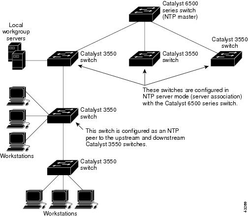
Cisco's implementation of NTP does not support stratum 1 service; it is not possible to connect to a radio or atomic clock. We recommend that the time service for your network be derived from the public NTP servers available on the IP Internet. Figure 5-1 shows a typical network example using NTP.
If the network is isolated from the Internet, Cisco's implementation of NTP allows a device to act as though it is synchronized through NTP, when in fact it has determined the time by using other means. Other devices then synchronize to that device through NTP.
When multiple sources of time are available, NTP is always considered to be more authoritative. NTP time overrides the time set by any other method.
Several manufacturers include NTP software for their host systems, and a publicly available version for systems running UNIX and its various derivatives is also available. This software allows host systems to be time-synchronized as well.
Figure 5-1 Typical NTP Network Configuration
Configuring NTP
Cisco Aironet 1300 Series Access Point/Bridges do not have a hardware-supported clock, and they cannot function as an NTP master clock to which peers synchronize themselves when an external NTP source is not available. These access point/bridges also have no hardware support for a calendar. As a result, the ntp update-calendar and the ntp master global configuration commands are not available.
This section contains this configuration information:
•
•
•
•
•
Default NTP Configuration
Table 5-4 shows the default NTP configuration.
NTP is disabled by default.
Configuring NTP Authentication
This procedure must be coordinated with the administrator of the NTP server; the information you configure in this procedure must be matched by the servers used by the access point/bridge to synchronize its time to the NTP server.
Beginning in privileged EXEC mode, follow these steps to authenticate the associations (communications between devices running NTP that provide for accurate timekeeping) with other devices for security purposes:
To disable NTP authentication, use the no ntp authenticate global configuration command. To remove an authentication key, use the no ntp authentication-key number global configuration command. To disable authentication of the identity of a device, use the no ntp trusted-key key-number global configuration command.
This example shows how to configure the access point/bridge to synchronize only to devices providing authentication key 42 in the device's NTP packets:
ap(config)# ntp authenticateap(config)# ntp authentication-key 42 md5 aNiceKeyap(config)# ntp trusted-key 42Configuring NTP Associations
An NTP association can be a peer association (this access point/bridge can either synchronize to the other device or allow the other device to synchronize to it), or it can be a server association (meaning that only this access point/bridge synchronizes to the other device, and not the other way around).
Beginning in privileged EXEC mode, follow these steps to form an NTP association with another device:
You need to configure only one end of an association; the other device can automatically establish the association. If you are using the default NTP version (version 3) and NTP synchronization does not occur, try using NTP version 2. Many NTP servers on the Internet run version 2.
To remove a peer or server association, use the no ntp peer ip-address or the no ntp server ip-address global configuration command.
This example shows how to configure the access point/bridge to synchronize its system clock with the clock of the peer at IP address 172.16.22.44 using NTP version 2:
ap(config)# ntp server 172.16.22.44 version 2Configuring NTP Broadcast Service
The communications between devices running NTP (known as associations) are usually statically configured; each device is given the IP addresses of all devices with which it should form associations. Accurate timekeeping is possible by exchanging NTP messages between each pair of devices with an association. However, in a LAN environment, NTP can be configured to use IP broadcast messages instead. This alternative reduces configuration complexity because each device can simply be configured to send or receive broadcast messages. However, the information flow is one-way only.
The access point/bridge can send or receive NTP broadcast packets on an interface-by-interface basis if there is an NTP broadcast server, such as a router, broadcasting time information on the network. The access point/bridge can send NTP broadcast packets to a peer so that the peer can synchronize to it. The access point/bridge can also receive NTP broadcast packets to synchronize its own clock. This section provides procedures for both sending and receiving NTP broadcast packets.
Beginning in privileged EXEC mode, follow these steps to configure the access point/bridge to send NTP broadcast packets to peers so that they can synchronize their clock to the access point/bridge:
To disable the interface from sending NTP broadcast packets, use the no ntp broadcast interface configuration command.
This example shows how to configure an interface to send NTP version 2 packets:
ap(config)# interface ethernet0/1ap(config-if)# ntp broadcast version 2Beginning in privileged EXEC mode, follow these steps to configure the access point/bridge to receive NTP broadcast packets from connected peers:
To disable an interface from receiving NTP broadcast packets, use the no ntp broadcast client interface configuration command. To change the estimated round-trip delay to the default, use the no ntp broadcastdelay global configuration command.
This example shows how to configure an interface to receive NTP broadcast packets:
ap(config)# interface ethernet0/1ap(config-if)# ntp broadcast clientConfiguring NTP Access Restrictions
You can control NTP access on two levels as described in these sections:
•
•
Creating an Access Group and Assigning a Basic IP Access List
Beginning in privileged EXEC mode, follow these steps to control access to NTP services by using access lists:
The access group keywords are scanned in this order, from least restrictive to most restrictive:
1.
2.
3.
4.
If the source IP address matches the access lists for more than one access type, the first type is granted. If no access groups are specified, all access types are granted to all devices. If any access groups are specified, only the specified access types are granted.
To remove access control to the access point/bridge NTP services, use the no ntp access-group {query-only | serve-only | serve | peer} global configuration command.
This example shows how to configure the access point/bridge to allow itself to synchronize to a peer from access list 99. However, the access point/bridge restricts access to allow only time requests from access list 42:
ap# configure terminalap(config)# ntp access-group peer 99ap(config)# ntp access-group serve-only 42ap(config)# access-list 99 permit 172.20.130.5ap(config)# access list 42 permit 172.20.130.6Disabling NTP Services on a Specific Interface
NTP services are enabled on all interfaces by default.
Beginning in privileged EXEC mode, follow these steps to disable NTP packets from being received on an interface:
To re-enable receipt of NTP packets on an interface, use the no ntp disable interface configuration command.
Configuring the Source IP Address for NTP Packets
When the access point/bridge sends an NTP packet, the source IP address is normally set to the address of the interface through which the NTP packet is sent. Use the ntp source global configuration command when you want to use a particular source IP address for all NTP packets. The address is taken from the specified interface. This command is useful if the address on an interface cannot be used as the destination for reply packets.
Beginning in privileged EXEC mode, follow these steps to configure a specific interface from which the IP source address is to be taken:
The specified interface is used for the source address for all packets sent to all destinations. If a source address is to be used for a specific association, use the source keyword in the ntp peer or ntp server global configuration command as described in the "Configuring NTP Associations" section.
Displaying the NTP Configuration
You can use two privileged EXEC commands to display NTP information:
•
•
For detailed information about the fields in these displays, refer to the Cisco IOS Configuration Fundamentals Command Reference for Release 12.3.
Configuring Time and Date Manually
If no other source of time is available, you can manually configure the time and date after the system is restarted. The time remains accurate until the next system restart. We recommend that you use manual configuration only as a last resort. If you have an outside source to which the access point/bridge can synchronize, you do not need to manually set the system clock.
This section contains this configuration information:
•
•
Setting the System Clock
If you have an outside source on the network that provides time services, such as an NTP server, you do not need to manually set the system clock.
Beginning in privileged EXEC mode, follow these steps to set the system clock:
This example shows how to manually set the system clock to 1:32 p.m. on July 23, 2001:
ap# clock set 13:32:00 23 July 2001Displaying the Time and Date Configuration
To display the time and date configuration, use the show clock [detail] privileged EXEC command.
The system clock keeps an authoritative flag that shows whether the time is authoritative (believed to be accurate). If the system clock has been set by a timing source such as NTP, the flag is set. If the time is not authoritative, it is used only for display purposes. Until the clock is authoritative and the authoritative flag is set, the flag prevents peers from synchronizing to the clock when the peers' time is invalid.
The symbol that precedes the show clock display has this meaning:
•
•
•
Configuring the Time Zone
Beginning in privileged EXEC mode, follow these steps to manually configure the time zone:
The minutes-offset variable in the clock timezone global configuration command is available for those cases where a local time zone is a percentage of an hour different from UTC. For example, the time zone for some sections of Atlantic Canada (AST) is UTC-3.5, where the 3 means 3 hours and .5 means 50 percent. In this case, the necessary command is clock timezone AST -3 30.
To set the time to UTC, use the no clock timezone global configuration command.
Configuring Summer Time (Daylight Saving Time)
Beginning in privileged EXEC mode, follow these steps to configure summer time (daylight saving time) in areas where it starts and ends on a particular day of the week each year:
The first part of the clock summer-time global configuration command specifies when summer time begins, and the second part specifies when it ends. All times are relative to the local time zone. The start time is relative to standard time. The end time is relative to summer time. If the starting month is after the ending month, the system assumes that you are in the southern hemisphere.
This example shows how to specify that summer time starts on the first Sunday in April at 02:00 and ends on the last Sunday in October at 02:00:
ap(config)# clock summer-time PDT recurring 1 Sunday April 2:00 last Sunday October 2:00Beginning in privileged EXEC mode, follow these steps if summer time in your area does not follow a recurring pattern (configure the exact date and time of the next summer time events):
The first part of the clock summer-time global configuration command specifies when summer time begins, and the second part specifies when it ends. All times are relative to the local time zone. The start time is relative to standard time. The end time is relative to summer time. If the starting month is after the ending month, the system assumes that you are in the southern hemisphere.
To disable summer time, use the no clock summer-time global configuration command.
This example shows how to set summer time to start on October 12, 2000, at 02:00, and end on April 26, 2001, at 02:00:
bridge(config)# clock summer-time pdt date 12 October 2000 2:00 26 April 2001 2:00Configuring a System Name and Prompt
You configure the system name on the access point/bridge to identify it. By default, the system name and prompt are bridge.
If you have not configured a system prompt, the first 20 characters of the system name are used as the system prompt. A greater-than symbol (>) is appended. The prompt is updated whenever the system name changes, unless you manually configure the prompt by using the prompt global configuration command.
Note
This section contains this configuration information:
•
Default System Name and Prompt Configuration
The default access point/bridge system name and prompt is bridge.
Configuring a System Name
Beginning in privileged EXEC mode, follow these steps to manually configure a system name:
When you set the system name, it is also used as the system prompt.
To return to the default host name, use the no hostname global configuration command.
Understanding DNS
The DNS protocol controls the Domain Name System (DNS), a distributed database with which you can map host names to IP addresses. When you configure DNS on your access point/bridge, you can substitute the host name for the IP address with all IP commands, such as ping, telnet, connect, and related Telnet support operations.
IP defines a hierarchical naming scheme that allows a device to be identified by its location or domain. Domain names are pieced together with periods (.) as the delimiting characters. For example, Cisco Systems is a commercial organization that IP identifies by a com domain name, so its domain name is cisco.com. A specific device in this domain, such as the File Transfer Protocol (FTP) system, is identified as ftp.cisco.com.
To keep track of domain names, IP has defined the concept of a domain name server, which holds a cache (or database) of names mapped to IP addresses. To map domain names to IP addresses, you must first identify the host names, specify the name server that is present on your network, and enable the DNS.
This section contains this configuration information:
•
Default DNS Configuration
Table 5-5 shows the default DNS configuration.
Table 5-5 Default DNS Configuration
DNS enable state
Disabled.
DNS default domain name
None configured.
DNS servers
No name server addresses are configured.
Setting Up DNS
Beginning in privileged EXEC mode, follow these steps to set up your access point/bridge to use the DNS:
If you use the access point/bridge IP address as its host name, the IP address is used and no DNS query occurs. If you configure a host name that contains no periods (.), a period followed by the default domain name is appended to the host name before the DNS query is made to map the name to an IP address. The default domain name is the value set by the ip domain-name global configuration command. If there is a period (.) in the host name, the IOS software looks up the IP address without appending any default domain name to the host name.
To remove a domain name, use the no ip domain-name name global configuration command. To remove a name server address, use the no ip name-server server-address global configuration command. To disable DNS on the access point/bridge, use the no ip domain-lookup global configuration command.
Displaying the DNS Configuration
To display the DNS configuration information, use the show running-config privileged EXEC command.
Creating a Banner
You can configure a message-of-the-day (MOTD) and a login banner. The MOTD banner appears on all connected terminals at login and is useful for sending messages that affect all network users (such as impending system shutdowns).
The login banner also appears on all connected terminals. It appears after the MOTD banner and before the login prompts.
Note
This section contains this configuration information:
•
Default Banner Configuration
The MOTD and login banners are not configured.
Configuring a Message-of-the-Day Login Banner
You can create a single or multiline message banner that appears on the screen when someone logs into the access point/bridge.
Beginning in privileged EXEC mode, follow these steps to configure a MOTD login banner:
To delete the MOTD banner, use the no banner motd global configuration command.
This example shows how to configure a MOTD banner for the access point/bridge using the pound sign (#) symbol as the beginning and ending delimiter:
ap(config)# banner motd #This is a secure site. Only authorized users are allowed.For access, contact technical support.#ap(config)#This example shows the banner displayed from the previous configuration:
Unix> telnet 172.2.5.4Trying 172.2.5.4...Connected to 172.2.5.4.Escape character is '^]'.This is a secure site. Only authorized users are allowed.For access, contact technical support.User Access VerificationPassword:Configuring a Login Banner
You can configure a login banner to appear on all connected terminals. This banner appears after the MOTD banner and before the login prompt.
Beginning in privileged EXEC mode, follow these steps to configure a login banner:
To delete the login banner, use the no banner login global configuration command.
This example shows how to configure a login banner for the access point/bridge using the dollar sign ($) symbol as the beginning and ending delimiter:
ap(config)# banner login $Access for authorized users only. Please enter your username and password.$ap(config)#