-
Cisco CPT Configuration Guide–CTC and Documentation Release 9.3 and Cisco IOS Release 15.1(01)SA
-
Preface
-
Understanding the Carrier Packet Transport System
-
Hardware
-
Configuring Ethernet Virtual Circuit
-
Configuring Multiprotocol Label Switching
-
Configuring MPLS–Transport Profile
-
Configuring Pseudowire
-
Configuring Quality of Service
-
Configuring High Availability
-
Configuring Resilient Ethernet Protocol
-
Configuring Link Aggregation Group and Link Aggregation Control Protocol
-
Configuring MAC Learning
-
Configuring Multicast VLAN Registration
-
Configuring IGMP Snooping
-
Configuring Performance Monitoring, RMON, OTN, and Port Provisioning
-
Configuring Local Authentication
-
Configuring Cisco Discovery Protocol
-
Alarm Troubleshooting
-
SNMP
-
CPT Error Messages
-
Network Element Defaults
-
Index
-
 Feedback
Contents
- Configuring Multicast VLAN Registration
- Using MVR in a Multicast Television Application
- Using MVR in a Multicast Television Application
- Configuring Multicast VLAN Registration
- NTP-J69 Configuring MVR Using Cisco IOS Commands
- DLP-J210 Enabling or Disabling MVR on a Bridge Domain Using Cisco IOS Commands
- DLP-J211 Enabling or Disabling MVR on the Source and Receiver EFPs Using Cisco IOS Commands
- DLP-J229 Viewing MVR Configuration Using Cisco IOS Commands
- NTP-J70 Configuring MVR Using CTC
- MVR Interaction with LAG
Configuring Multicast VLAN Registration
This chapter describes Multicast VLAN Registration and procedures to configure Multicast VLAN Registration.
- Using MVR in a Multicast Television Application
- Configuring Multicast VLAN Registration
- MVR Interaction with LAG
Using MVR in a Multicast Television Application
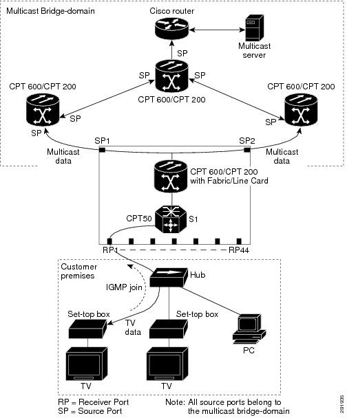
In a multicast television application, a PC or a television with a set-top box can receive the multicast stream. Multiple set-top boxes or PCs can be connected to one subscriber port, which is an EFP configured as the MVR receiver. Figure 1 is an example configuration. The DHCP assigns an IP address to the set-top box or the PC. When a subscriber selects a channel, the set-top box or PC sends an IGMP report to the CPT node (CPT 200 or CPT 600 along with CPT 50) to join the appropriate multicast. If the IGMP report matches one of the configured IP multicast group addresses, the CPT system modifies the hardware address table to include this receiver EFP and bridge-domain as a forwarding destination of the specified multicast stream when it is received from the multicast bridge-domain.
When a subscriber changes channels or turns off the television, the set-top box sends an IGMP leave message for the multicast stream. The CPT system sends a MAC-based general query through the receiver EFP bridge-domain. If there is another set-top box in the bridge-domain still subscribing to this group, that set-top box must respond within the maximum response time specified in the query. If the CPT system does not receive a response, it eliminates the receiver EFP as a forwarding destination for this group.
If the Immediate Leave feature is enabled on a receiver EFP, the EFP leaves a multicast group more quickly. Without Immediate Leave, when the CPT system receives an IGMP leave message from a subscriber on a receiver EFP, it sends out an IGMP group specific query on that EFP and waits for the IGMP group membership reports. If no reports are received in a configured time period, the receiver EFP is removed from the multicast group membership. With Immediate Leave, an IGMP query is not sent from the receiver EFP where the IGMP leave was received. As soon as the leave message is received, the receiver EFP is removed from the multicast group membership, which speeds up leave latency. Enable the Immediate Leave feature only on receiver EFPs to which a single receiver device is connected.
MVR eliminates the need to duplicate television-channel multicast traffic for subscribers in each bridge-domain. Multicast traffic for all channels is only sent around the bridge domain source EFPs —only on the multicast bridge-domain. The IGMP leave and join messages are in the bridge-domain to which the subscriber port is assigned. These messages dynamically register for streams of multicast traffic in the multicast bridge-domain on the Layer 3 device. The CPT node (CPT 200 or CPT 600 along with CPT 50) modifies the forwarding behavior to allow the traffic to be forwarded from the multicast bridge domain to the subscriber port in a different bridge-domain, thereby selectively allowing traffic to cross between the two bridge-domains.
IGMP reports are sent to the same IP multicast group address as the multicast data. The CPT node (CPT 200 or CPT 600 along with CPT 50) must capture all IGMP join and leave messages from the receiver EFPs and forward them to the multicast bridge domain of the source EFP.
Using MVR in a Multicast Television Application
In a multicast television application, a PC or a television with a set-top box can receive the multicast stream. Multiple set-top boxes or PCs can be connected to one subscriber port, which is an EFP configured as the MVR receiver. Figure 1 is an example configuration. The DHCP assigns an IP address to the set-top box or the PC. When a subscriber selects a channel, the set-top box or PC sends an IGMP report to the CPT node (CPT 200 or CPT 600 along with CPT 50) to join the appropriate multicast. If the IGMP report matches one of the configured IP multicast group addresses, the CPT system modifies the hardware address table to include this receiver EFP and bridge-domain as a forwarding destination of the specified multicast stream when it is received from the multicast bridge-domain.
When a subscriber changes channels or turns off the television, the set-top box sends an IGMP leave message for the multicast stream. The CPT system sends a MAC-based general query through the receiver EFP bridge-domain. If there is another set-top box in the bridge-domain still subscribing to this group, that set-top box must respond within the maximum response time specified in the query. If the CPT system does not receive a response, it eliminates the receiver EFP as a forwarding destination for this group.
If the Immediate Leave feature is enabled on a receiver EFP, the EFP leaves a multicast group more quickly. Without Immediate Leave, when the CPT system receives an IGMP leave message from a subscriber on a receiver EFP, it sends out an IGMP group specific query on that EFP and waits for the IGMP group membership reports. If no reports are received in a configured time period, the receiver EFP is removed from the multicast group membership. With Immediate Leave, an IGMP query is not sent from the receiver EFP where the IGMP leave was received. As soon as the leave message is received, the receiver EFP is removed from the multicast group membership, which speeds up leave latency. Enable the Immediate Leave feature only on receiver EFPs to which a single receiver device is connected.
MVR eliminates the need to duplicate television-channel multicast traffic for subscribers in each bridge-domain. Multicast traffic for all channels is only sent around the bridge domain source EFPs —only on the multicast bridge-domain. The IGMP leave and join messages are in the bridge-domain to which the subscriber port is assigned. These messages dynamically register for streams of multicast traffic in the multicast bridge-domain on the Layer 3 device. The CPT node (CPT 200 or CPT 600 along with CPT 50) modifies the forwarding behavior to allow the traffic to be forwarded from the multicast bridge domain to the subscriber port in a different bridge-domain, thereby selectively allowing traffic to cross between the two bridge-domains.
IGMP reports are sent to the same IP multicast group address as the multicast data. The CPT node (CPT 200 or CPT 600 along with CPT 50) must capture all IGMP join and leave messages from the receiver EFPs and forward them to the multicast bridge domain of the source EFP.
Configuring Multicast VLAN Registration
This section provides MVR configuration guidelines and limitations, and procedures to configure MVR using Cisco IOS commands and CTC.
MVR Configuration Guidelines and Limitations
- Receiver EFPs on a CPT system can be in different bridge-domains, but should not belong to the multicast bridge-domain.
- The maximum number of multicast entries (MVR group addresses) that can be configured on a CPT system is 2000.
- The CPT system supports up to 20 MVR bridge-domains.
- The maximum number of receiver EFPs on an MVR bridge-domain is 128.
- Because an MVR on the CPT system uses IP multicast addresses instead of MAC multicast addresses, aliased IP multicast addresses are allowed on the CPT system.
- MVR can coexist with IGMP snooping on a CPT system.
- MVR data received on an MVR receiver EFP is not forwarded to MVR source EFPs.
- A physical port can have only one receiver EFP for a given MVR bridge domain.
- CPT system does not support MVR in point to point bridge-domains.
- Query response time is 0.5 second.
- It is mandatory to untag the packets before they enter the bridge domain:
- Following configuration restrictions are applicable while configuring MVR source EFPs on the CPT system:
To configure MVR using Cisco IOS commands, see NTP-J69 Configuring MVR Using Cisco IOS Commands.
To configure MVR using CTC, see NTP-J70 Configuring MVR Using CTC.
NTP-J69 Configuring MVR Using Cisco IOS Commands
Procedure
Step 1 Complete the DLP-J210 Enabling or Disabling MVR on a Bridge Domain Using Cisco IOS Commands. Step 2 Complete the DLP-J211 Enabling or Disabling MVR on the Source and Receiver EFPs Using Cisco IOS Commands. Step 3 (Optional) Complete the DLP-J229 Viewing MVR Configuration Using Cisco IOS Commands. Stop. You have completed this procedure.
DLP-J210 Enabling or Disabling MVR on a Bridge Domain Using Cisco IOS Commands
ProcedureExamples:
The following example shows how to enable MVR on bridge domain 22 and configure the group address.
Router(config)# bridge-domain 22
Router(config-bdomain)# mvr
Router(config-bdomain)# mvr group 228.1.23.4 5
Router(config-bdomain)# end
The following example shows how to disable MVR on bridge domain 22 and group address.
Router(config)# bridge-domain 22
Router(config-bdomain)# no mvr
Router(config-bdomain)# no mvr group 228.1.23.4 5
Router(config-bdomain)# end
The following example shows how to verify the MVR multicast group addresses on the CPT system.
Router# show mvr groupsMVR multicast VLAN: 20 MVR max Multicast Groups allowed: 2000 MVR current multicast groups: 20 MVR groups: Group start Group end Type Count/Mask --------------- --------------- ----- --------------- 230.1.2.3 230.1.2.22 count 20DLP-J211 Enabling or Disabling MVR on the Source and Receiver EFPs Using Cisco IOS Commands
Procedure
Purpose This procedure enables or disables MVR on the source and receiver EFPs: Tools/Equipment None Prerequisite Procedures DLP-J210 Enabling or Disabling MVR on a Bridge Domain Using Cisco IOS Commands Required/As Needed As needed Onsite/Remote Remote Security Level None
NoteUsers must configure an MVR bridge domain before configuring the MVR source and receiver EFPs. Step 1 through Step 9 explains MVR configuration of the source EFP. Step 8 through Step 16 explains MVR configuration of the receiver EFP.
The mvr type {source | receiver bridge-domain id [vlan id] [immediate]} command is used to configure the EFPs, where bridge-domain id [vlan id] [immediate] is only applicable to the receiver EFPs.
Examples:
To return the CPT system to its default settings, use the no mvr [type type| immediate | vlan vlan-id] command in the interface configuration mode.
This example shows how to configure an EFP as a receiver and receive multicast traffic sent to the multicast group address. It also shows how to enable Immediate Leave on the receiver EFP and verify the results.
Router(config)# interface TengigabitEthernet 6/3
Router(config-if)# service instance 100 ethernet
Router(config-if-srv)# encapsulation dot1q 10
Router(config-if-srv)# rewrite ingress tag pop 1 symmetric
Router(config-if-srv)# bridge-domain 100
Router(config-if-srv)# mvr type receiver bridge-domain 22 immediate
end
Router(config)#show mvr receiver
This example shows how to disable MVR on the receiver EFP.
Router(config)# interface TengigabitEthernet 6/3
Router(config-if)# service instance 100 ethernet
Router(config-if-srv)# no mvr type receiver bridge-domain 22 immediate
Router(config-if-srv)# no service instance 100 ethernet
This example shows how to configure an EFP as a receiver with encapsulation range, and receive multicast traffic sent to the multicast group address. It also shows how to enable Immediate Leave on the receiver EFP.
Router(config)# interface gi36/1
Router(config-if)# service instance 10 ethernet
Router(config-if-srv)# encapsulation dot1q 100-1000
Router(config-if-srv)# rewrite ingress tag push dot1q 100 symmetric
Router(config-if-srv)# bridge-domain 100
Router(config-if-srv)# mvr type receiver bridge-domain 22 immediate vlan 200
This example shows how to configure an EFP as a receiver with encapsulation ID, and receive multicast traffic sent to the multicast group address. It also shows how to enable Immediate Leave on the receiver EFP.
Router(config)# interface gi36/2
Router(config-if)# service instance 10 ethernet
Router(config-if-srv)# encapsulation dot1q 10
Router(config-if-srv)# rewrite ingress tag push dot1q 100 symmetric
Router(config-if-srv)# bridge-domain 100
Router(config-if-srv)# mvr type receiver bridge-domain 22 immediate
This example shows how to enable MVR on the source EFP.
Router(config)# TengigabitEthernet 6/3
Router(config-if)# service instance 100 ethernet
Router(config-if-srv)# encapsulation dot1q 12
Router(config-if-srv)# rewrite ingress tag pop 1 symmetric
Router(config-if-srv)# bridge-domain 22
Router(config-if-srv)# mvr type source
This example shows how to disable MVR on the source EFP.
Router(config)# TengigabitEthernet 6/3
Router(config-if)# service instance 100 ethernet
Router(config-if-srv)# no mvr type source
Router(config-if-srv)# no service instance 100 ethernet
This example shows how to enable MVR on the bridge domains and configure source MVR EFPs and receiver MVR EFPs.
! Enabling MVR on the bridge domain 22 and bridge domain 30.
Router(config)# bridge-domain 22
Router(config-bdomain)# mvr
Router(config-bdomain)# mvr group 225.0.0.1 5
Router(config-bdomain)# end

Router(config)# bridge-domain 30
Router(config-bdomain)# mvr
Router(config-bdomain)# mvr group 226.0.0.1 5

! Configuring source EFP on the bridge domain 22.
Router(config)# TengigabitEthernet 6/3
Router(config-if)# service instance 100 ethernet
Router(config-if-srv)# encapsulation dot1q 12
Router(config-if-srv)# rewrite ingress tag pop 1 symmetric
Router(config-if-srv)# bridge-domain 22
Router(config-if-srv)# mvr type source

! Configuring receiver EFP on the bridge domain 50.
Router(config)# interface TengigabitEthernet 5/3
Router(config-if)# service instance 100 ethernet
Router(config-if-srv)# encapsulation dot1q 10
Router(config-if-srv)# rewrite ingress tag pop 1 symmetric
Router(config-if-srv)# bridge-domain 50
Router(config-if-srv)# mvr type receiver bridge-domain 22 immediate


! Configuring source EFP on the bridge domain 30.
Router(config)# TengigabitEthernet 4/3
Router(config-if)# service instance 100 ethernet
Router(config-if-srv)# encapsulation dot1q 12
Router(config-if-srv)# rewrite ingress tag pop 1 symmetric
Router(config-if-srv)# bridge-domain 30
Router(config-if-srv)# mvr type source

! Configuring receiver EFP on the bridge domain 60.
Router(config)# interface TengigabitEthernet 2/3
Router(config-if)# service instance 100 ethernet
Router(config-if-srv)# encapsulation dot1q 10
Router(config-if-srv)# rewrite ingress tag push dot1q 100 symmetric
Router(config-if-srv)# bridge-domain 60
Router(config-if-srv)# mvr type receiver bridge-domain 30 immediate

! Configuring receiver EFP on the bridge domain 60 encapsulation range.
Router(config)# interface TengigabitEthernet 2/4
Router(config-if)# service instance 200 ethernet
Router(config-if-srv)# encapsulation dot1q 10-1000
Router(config-if-srv)# bridge-domain 60
Router(config-if-srv)# mvr type receiver bridge-domain 30 immediate vlan 20
DLP-J229 Viewing MVR Configuration Using Cisco IOS Commands
Procedure
Command or Action Purpose
Step 1 enable
Example:Router> enableEnables privileged EXEC mode.
Step 2 show mvr [source-ports] [receiver-ports] [groups]
Example:Router# show mvrDisplays MVR status and values for all the bridge-domains where MVR is enabled. It provides the number of groups configured per bridge domain and displays all receiver and source EFPs. Step 3 show ip igmp snooping [groups] [querier]
Example:Router# show ip igmp snooping(Optional) Displays the querier and snooping information.
Examples
This example shows how to view MVR receiver port configuration.
Router# show mvr receiver-portsJoins: v1,v2,v3 counter shows total IGMP joins v3 counter shows IGMP joins received with both MVR and non-MVR groups Port VLAN Status Immediate Joins Leave (v1,v2,v3) (v3) --------- ---- ------------- ---------- ---------- ---------- Po10 100 ACTIVE /UP DISABLED 0 0 Gi40/2 100 ACTIVE /UP DISABLED 0 0 Po10 200 ACTIVE /UP DISABLED 0 0 Gi40/2 101 ACTIVE /UP DISABLED 0 0This example shows how to view MVR source port configuration.
Router# show mvr source-portsJoins: v1,v2,v3 counter shows total IGMP joins v3 counter shows IGMP joins received with both MVR and non-MVR groups Port VLAN Status Immediate Joins Leave (v1,v2,v3) (v3) --------- ---- ------------- ---------- ---------- ---------- Gi36/2 1 ACTIVE /UP DISABLED 0 0 Gi36/2 2 ACTIVE /UP DISABLED 0 0This example shows how to view MVR group details.
Router# show mvr groupsMVR multicast VLAN: 1 MVR max Multicast Groups allowed: 2000 MVR current multicast groups: 60 MVR groups: Group start Group end Type Count/Mask --------------- --------------- ----- --------------- 224.1.1.1 224.1.1.20 count 20 225.1.1.1 225.1.1.20 count 20 229.1.1.1 229.1.1.10 count 10 230.1.1.1 230.1.1.10 count 10 MVR multicast VLAN: 2 MVR max Multicast Groups allowed: 2000 MVR current multicast groups: 60 MVR groups: Group start Group end Type Count/Mask --------------- --------------- ----- --------------- 224.1.1.1 224.1.1.20 count 20 225.1.1.1 225.1.1.20 count 20 229.1.1.1 229.1.1.10 count 10 230.1.1.1 230.1.1.10 count 10This example shows how to view snooping details.
Router# show ip igmp snooping groupsFlags: I -- IGMP snooping, S -- Static, P -- PIM snooping, A -- ASM mode Vlan Group/source Type Version Port List ----------------------------------------------------------------------- 1 229.1.1.1 I v3 Po10 Gi40/2 1 229.1.1.2 I v3 Po10 Gi40/2 1 229.1.1.3 I v3 Po10 Gi40/2 1 229.1.1.4 I v3 Po10 Gi40/2 1 229.1.1.5 I v3 Po10 Gi40/2 1 229.1.1.6 I v3 Po10 Gi40/2 1 229.1.1.7 I v3 Po10 Gi40/2 1 229.1.1.8 I v3 Po10 Gi40/2 1 229.1.1.9 I v3 Po10 Gi40/2 1 229.1.1.10 I v3 Po10 Gi40/2This example shows how to view querier details.
Router# show ip igmp snooping querierVlan IP Address IGMP Version Port ------------------------------------------------------------- 1 12.12.12.12 v3 Gi36/2This example shows how to view generic MVR details.
Router# show mvrMVR Running: TRUE MVR multicast VLAN: 2 MVR Max Multicast Groups: 2000 MVR Current multicast groups: 100 MVR Global query response time: 5 (tenths of sec)NTP-J70 Configuring MVR Using CTC
Procedure
Purpose This procedure explains how to enable MVR on the bridge domain, create a source MVR EFP, a receiver MVR EFP, and disable MVR. Tools/Equipment None Prerequisite Procedures Create an Ethernet Virtual Private LAN EVC circuit with the following conditions:
Note While creating an EVPLAN circuit, the source EFP and the receiver EFP of the same MVR bridge domain cannot be present on the same physical port.
To create an EVC circuit, seeDLP-J2 Create an EVC Circuit Using CTC .
Required/As Needed As needed Onsite/Remote Remote Security Level None
NoteAn MVR source is configured on the EVPLAN circuit that has MVR enabled; however, an MVR receiver is configured on the EVPLAN circuit that does not have MVR enabled.
Step 1 Complete the NTP-J22 Log into CTC procedure at a node where you want to enable MVR. Step 2 In the node view, click the Layer2+ tab. Step 3 Click Carrier Ethernet. Step 4 From the list of Ethernet Virtual Circuits (EVCs), select an Ethernet Virtual Private LAN EVC circuit to enable MVR. Step 5 Click Edit. The Edit Circuit dialog box appears. In the MVR tab, specify the multicast settings for the bridge domain as described in the subsequent steps. Step 6 To enable MVR on the bridge domain, do the following:
Step 7 To add multicast IP addresses for the bridge domain, do the following:
Step 8 To create an MVR source EFP, do the following:
Step 9 To create an MVR receiver EFP, do the following:
Step 10 To disable MVR on the bridge-domain, source MVR EFP, or receiver MVR EFP, do the following: Step 11 To view the MVR configuration, refer to the procedure explained in DLP-J56 Open the Cisco IOS Configuration Mode and View the Feature Configuration Details Using CTC.
MVR Interaction with LAG
We can add a LAG interface to a bridge domain which has MVR enabled.
The following example shows the source EFP configuration, which is part of the LAG interface that is a member of the MVR-enabled bridge domain.
! Enabling MVR on the bridge domain.
Router(config)# bridge-domain 30
Router(config-bdomain)# mvr
Router(config-bdomain)# mvr group 239.0.0.1 10

! Configuring source EFP on the bridge domain 30.
Router(config)# interface port-channel 10
Router(config-if)# service instance 10 ethernet
Router(config-if-srv)# encapsulation dot1q 10
Router(config-if-srv)# bridge-domain 30
Router(config-if-srv)# mvr type source
Router(config-if-srv)# exit

! Adding members to the port channel interface.
Router(config)# interface ten 6/1
Router(config-if)# channel-group 10

Router(config)# interface ten 6/2
Router(config-if)# channel-group 10

! Configuring receiver EFP on the bridge domain 100.
Router(config)# interface gi36/5
Router(config-if)# service instance 10 ethernet
Router(config-if-srv)# encapsulation dot1q 100
Router(config-if-srv)# bridge-domain 100
Router(config-if-srv)# mvr type receiver bridge-domain 30

! Configuring receiver EFP on the bridge domain 200.
Router(config)# interface gi36/6
Router(config-if)# service instance 10 ethernet
Router(config-if-srv)# encapsulation dot1q 100
Router(config-if-srv)# rewrite ingress tag push dot1q 100 symmetric
Router(config-if-srv)# bridge-domain 200
Router(config-if-srv)# mvr type receiver bridge-domain 30
The following example shows the receiver EFP configuration, which is part of the LAG interface.
! Enabling MVR on the bridge domain.
Router(config)# bridge-domain 30
Router(config-bdomain)# mvr
Router(config-bdomain)# mvr group 228.1.23.4 5
Router(config-bdomain)# end

! Configuring the source EFP.
Router(config)# interface ten 6/1
Router(config-if)# service instance 10 ethernet
Router(config-if-srv)# encapsulation dot1q 10 second-dot1q 30
Router(config-if-srv)# bridge-domain 30
Router(config-if-srv)# mvr type source

! Configuring the receiver EFP.
Router(config)# interface port-channel 10
Router(config-if)# service instance 10 ethernet
Router(config-if-srv)# encapsulation dot1q 10
Router(config-if-srv)# bridge-domain 100
Router(config-if-srv)# mvr type receiver bridge-domain 30

! Adding members to the port channel interface.
Router(config)# interface gi36/5
Router(config-if)# channel-group 10

Router(config)# interface gi36/6
Router(config-if)# channel-group 10

! Configuring the receiver EFP.
Router(config)# interface gi36/6
Router(config-if)# service instance 10 ethernet
Router(config-if-srv)# encapsulation dot1q 100
Router(config-if-srv)# rewrite ingress tag push dot1q 100 symmetric
Router(config-if-srv)# bridge-domain 200
Router(config-if-srv)# mvr type receiver bridge-domain 30