-
Cisco CPT Configuration Guide–CTC and Documentation Release 9.3 and Cisco IOS Release 15.1(01)SA
-
Preface
-
Understanding the Carrier Packet Transport System
-
Hardware
-
Configuring Ethernet Virtual Circuit
-
Configuring Multiprotocol Label Switching
-
Configuring MPLS–Transport Profile
-
Configuring Pseudowire
-
Configuring Quality of Service
-
Configuring High Availability
-
Configuring Resilient Ethernet Protocol
-
Configuring Link Aggregation Group and Link Aggregation Control Protocol
-
Configuring MAC Learning
-
Configuring Multicast VLAN Registration
-
Configuring IGMP Snooping
-
Configuring Performance Monitoring, RMON, OTN, and Port Provisioning
-
Configuring Local Authentication
-
Configuring Cisco Discovery Protocol
-
Alarm Troubleshooting
-
SNMP
-
CPT Error Messages
-
Network Element Defaults
-
Index
-
 Feedback
Contents
- Configuring MPLS–Transport Profile
- Understanding Multiprotocol Label Switching Transport Profile
- Understanding MPLS–TP Operations, Administration, and Maintenance
- Multiprotocol Label Switching Transport Profile Configuration Procedures
- NTP-J36 Configure Global Settings for Multiprotocol Label Switching Transport Profile
- DLP-J95 Configure Global Settings for Multiprotocol Label Switching Transport Profile Using Cisco IOS Commands
- DLP-J96 Configure Global Settings for Multiprotocol Label Switching Transport Profile Using CTC
- NTP-J40 Specify Static Label Range
- DLP-J103 Specify Static Label Range Using Cisco IOS Commands
- DLP-J104 Specify Static Label Range Using CTC
- Understanding Bidirectional Forwarding Detection
- NTP-J37 Configure BFD Templates
- DLP-J97 Create and Configure BFD Templates Using Cisco IOS Commands
- DLP-J98 Create and Configure BFD Templates Using CTC
- Understanding Multiprotocol Label Switching Transport Profile Link Numbers
- MPLS-TP over Ethernet Without IP Addressing
- NTP-J38 Configure an MPLS–TP Link
- DLP-J99 Configure an MPLS–TP Link Using Cisco IOS Commands
- DLP-J226 Configure an MPLS–TP Link Without IP Addresses Using Cisco IOS Commands
- DLP-J100 Configure an MPLS–TP Link Number Using CTC
- NTP-J39 Create a Static OAM Class
- DLP-J101 Create a Static OAM Class Using Cisco IOS Commands
- DLP-J102 Create a Static OAM Class Using CTC
- NTP-J67 Create a Provisionable Patchcord Using CTC
- Understanding Multiprotocol Label Switching Transport Profile Tunnels
- Understanding MPLS–TP LSPs
- Tunnel Midpoints and Endpoints
- NTP-J41 Configure an MPLS-TP Tunnel
- DLP-J105 Configure Tunnel Midpoints Using Cisco IOS Commands
- DLP–J106 Configure Tunnel Endpoints Using Cisco IOS Commands
- DLP-J107 Create an MPLS–TP Tunnel Using CTC
- DLP-J208 Edit MPLS–TP Tunnel Attributes Using CTC
- DLP-J368 Query an MPLS-TP Circuit Using CTC
- NTP-J107 Perform ping and traceroute Operations on Services Using CTC
- MPLS–TP Show Commands
Configuring MPLS–Transport Profile
This chapter describes the MPLS–Transport Profile and procedures to configure MPLS–Transport Profile.
- Understanding Multiprotocol Label Switching Transport Profile
- Understanding MPLS–TP Operations, Administration, and Maintenance
- Multiprotocol Label Switching Transport Profile Configuration Procedures
- NTP-J36 Configure Global Settings for Multiprotocol Label Switching Transport Profile
- DLP-J95 Configure Global Settings for Multiprotocol Label Switching Transport Profile Using Cisco IOS Commands
- DLP-J96 Configure Global Settings for Multiprotocol Label Switching Transport Profile Using CTC
- NTP-J40 Specify Static Label Range
- DLP-J103 Specify Static Label Range Using Cisco IOS Commands
- DLP-J104 Specify Static Label Range Using CTC
- Understanding Bidirectional Forwarding Detection
- Understanding Multiprotocol Label Switching Transport Profile Link Numbers
- NTP-J39 Create a Static OAM Class
- DLP-J101 Create a Static OAM Class Using Cisco IOS Commands
- DLP-J102 Create a Static OAM Class Using CTC
- NTP-J67 Create a Provisionable Patchcord Using CTC
- Understanding Multiprotocol Label Switching Transport Profile Tunnels
- MPLS–TP Show Commands
Understanding Multiprotocol Label Switching Transport Profile
Multiprotocol Label Switching Transport Profile (MPLS–TP) is a carrier–grade packet transport technology that enables service providers to move from Synchronous Optical Networking (SONET) and Synchronous Digital Hierarchy (SDH) time–division multiplexing (TDM) to packet switching. MPLS–TP enables MPLS to be deployed in a transport network to support packet transport services with a similar degree of predictability to that found in existing transport networks.
The goal of MPLS–TP is to provide connection–oriented transport for packet and TDM services over optical networks leveraging the widely deployed MPLS technology. Operations, Administration, and Maintenance (OAM) and resiliency features are defined and implemented in MPLS–TP to ensure the capabilities needed for carrier–grade packet transport networks—scalable operations, high availability, performance monitoring and multidomain support.
MPLS–TP defines a profile of MPLS targeted at transport applications and networks. This profile specifies the MPLS characteristics and extensions required to meet the transport requirements.
Note
MPLS–TP supports only point–to–point Layer 2 VPN service in this release. The point–to–point Layer 2 VPN service is called Virtual Private Wire Service (VPWS). MPLS–TP supports only static pseudowires in this release.Key Features
The key features of MPLS–TP are as follows:
- Connection–oriented.
- Carries Layer 3 and Layer 2 services.
- Runs over IEEE Ethernet PHYs, OTN, WDM and so on.
- Static and bidirectional label-switched path (LSP) provisioning.
- OAM functions similar to those available in traditional optical transport networks such as SONET or SDH are provided. These OAM functions belong to the MPLS–TP data plane and are independent from the control plane.
- Fault propagation through Bidirectional Fault Detection (BFD), Link Down Indication (LDI), and Lockout Request (LKR) messages.
- 1:1 revertive path protection.
- IP–less provisioning of tunnels.
- Network provisioning through CTC.
- Traffic switchover time from working LSP to protect LSP and vice versa is up to 50 milliseconds.
Planes in MPLS–TP
The three planes in MPLS–TP perform the following functions:
Plane Functions Control plane through CTC Data plane Forwards data packets Management plane Configuration The control plane is decoupled from the data plane such that the failures in the control plane do not affect the data plane and vice versa.
Restrictions
The following restrictions apply to MPLS–TP:
- Penultimate hop popping is not supported. Only ultimate hop popping is supported, because the label mappings are configured at the MPLS–TP end points.
- MPLS–TP link numbers are not configured on the interfaces for which Multiprotocol Label Switching Traffic Engineering (MPLS-TE) is enabled and vice versa.
- IPv6 addressing is not supported.
Understanding MPLS–TP Operations, Administration, and Maintenance
Several Operations, Administration, and Maintenance (OAM) protocols and messages support the provisioning and maintenance of MPLS–TP tunnels and bidirectional LSPs. The OAM messages are used for fault management, connection verification, continuity check, and other functions. The timers can be configured for each OAM message.
The following OAM messages are forwarded along the specified LSP:
- OAM fault management—Link Down Indication (LDI) and Lockout Request (LKR) messages
- OAM connection verification—ping and traceroute messages
- OAM continuity check—Bidirectional Fault Detection (BFD) messages. min_tx and min_rx are 4 milliseconds.
The following messages are forwarded along the specified pseudowire:
- Static pseudowire OAM messages
- Pseudowire ping and traceroute messages
- Pseudowire BFD messages. min_tx and min_rx are 50 milliseconds.
LDI and LKR Messages
The LDI messages are generated at midpoint nodes when a link failure is detected. The LKR messages are sent from a midpoint node to the reachable endpoint when an interface is administratively shut. When a lockout command is configured on either the working or the protect LSP, an LDI message is sent from the local endpoint to the remote endpoint.
LSP Ping and Trace Messages
For MPLS–TP connectivity verification, ping mpls tp and trace mpls tp commands can be used to specify that the echo requests must be sent along the working LSP or the protect LSP, or the locked out working or protect LSP.
BFD Messages
BFD sessions running on MPLS-TP LSPs can be configured. These sessions run on both the working LSP and the protect LSP. BFD provides continuity check for MPLS–TP LSPs to detect forwarding failures between two adjacent routers. When BFD is enabled on an MPLS–TP tunnel interface, the MPLS–TP client creates separate BFD sessions for working and protect LSPs. A single set of BFD timers is configured on the tunnel that applies to both the working and protect LSPs.
Multiprotocol Label Switching Transport Profile Configuration Procedures
The following procedures can be performed using Cisco IOS commands to configure MPLS–TP:
- DLP-J95 Configure Global Settings for Multiprotocol Label Switching Transport Profile Using Cisco IOS Commands
- DLP-J103 Specify Static Label Range Using Cisco IOS Commands
- DLP-J97 Create and Configure BFD Templates Using Cisco IOS Commands
- DLP-J99 Configure an MPLS–TP Link Using Cisco IOS Commands
- DLP-J226 Configure an MPLS–TP Link Without IP Addresses Using Cisco IOS Commands
- DLP-J101 Create a Static OAM Class Using Cisco IOS Commands
- DLP-J105 Configure Tunnel Midpoints Using Cisco IOS Commands
- DLP–J106 Configure Tunnel Endpoints Using Cisco IOS Commands
The following procedures can be performed using CTC to configure MPLS–TP:
- DLP-J96 Configure Global Settings for Multiprotocol Label Switching Transport Profile Using CTC
- DLP-J104 Specify Static Label Range Using CTC
- DLP-J98 Create and Configure BFD Templates Using CTC
- DLP-J100 Configure an MPLS–TP Link Number Using CTC
- DLP-J102 Create a Static OAM Class Using CTC
- DLP-J107 Create an MPLS–TP Tunnel Using CTC
- DLP-J208 Edit MPLS–TP Tunnel Attributes Using CTC
NTP-J36 Configure Global Settings for Multiprotocol Label Switching Transport Profile
Procedure
- DLP-J95 Configure Global Settings for Multiprotocol Label Switching Transport Profile Using Cisco IOS Commands
- DLP-J96 Configure Global Settings for Multiprotocol Label Switching Transport Profile Using CTC
Stop. You have completed this procedure.
DLP-J95 Configure Global Settings for Multiprotocol Label Switching Transport Profile Using Cisco IOS Commands
ProcedureExample: Configure Global Settings for MPLS–TP
The following example shows how to configure the global settings for MPLS–TP using Cisco IOS commands:
Router> enable
Router# configure terminal
Router(config)# mpls tp
Router(config-mpls-tp)# router-id 209.165.200.225
Router(config-mpls-tp)# global-id 1
Router(config-mpls-tp)# fault-oam refresh-timer 10
Router(config-mpls-tp)# wtr-timer 25
Router(config-mpls-tp)# exit
DLP-J96 Configure Global Settings for Multiprotocol Label Switching Transport Profile Using CTC
Procedure
Step 1 Complete the NTP-J22 Log into CTC procedure at a node on the network where you want to configure the global settings for MPLS–TP. Step 2 From the View menu, choose Go to Home View. Step 3 Right-click the fabric or line card and choose Open Packet Transport System View. The Packet Transport System View dialog box appears. Step 4 Click the Provisioning tab. Step 5 From the left pane, click MPLS TP. Step 6 Click the Global Settings tab. Step 7 Enter the router IP address in the Node ID field. This IP address need not be the loopback IP address. Step 8 In the TP Fault OAM area, enter the number of seconds in the Refresh Timer field to specify how often the static OAM packets must be sent out. Step 9 Click Apply to save the configuration. Step 10 Return to your originating procedure (NTP).
NTP-J40 Specify Static Label Range
Procedure
- DLP-J103 Specify Static Label Range Using Cisco IOS Commands
- DLP-J104 Specify Static Label Range Using CTC
Stop. You have completed this procedure.
DLP-J103 Specify Static Label Range Using Cisco IOS Commands
Procedure
Purpose This procedure specifies the static label range using Cisco IOS commands.
Tools/Equipment None Prerequisite Procedures None Required/As Needed As needed Onsite/Remote Onsite or remote Security Level Provisioning or higher You must specify the static label range before provisioning the MPLS–TP tunnel.
DLP-J104 Specify Static Label Range Using CTC
Procedure
Purpose This procedure specifies the static label range using CTC.
Tools/Equipment None Prerequisite Procedures None Required/As Needed As needed Onsite/Remote Onsite or remote Security Level Provisioning or higher You must specify the static label range before provisioning the MPLS–TE or MPLS–TP tunnel.
Step 1 Complete the NTP-J22 Log into CTC procedure at a node on the network where you want to specify the static label range. Step 2 From the View menu, choose Go to Home View. Step 3 Right-click the fabric or line card and choose Open Packet Transport System View. The Packet Transport System View dialog box appears. Step 4 Click the Provisioning tab. Step 5 From the left pane, click Label Range. Step 6 In the MPLS Static Label Range area, enter the minimum label value in the Min Label field. Step 7 Enter the maximum label value in the Max Label field. The static label range specified in the static label applies to both the pseudowire and MPLS–TP tunnel. The valid range of static and dynamic labels is from 16 to 8000. You do not need to specify the values for dynamic labels. The dynamic label range is automatically calculated by CTC based on the values specified in the static label range. For example, if you choose 100 to 1000 for static labels, the dynamic label range is set to 1001 to 8000.
Step 8 Click Apply to specify the static label range. Step 9 Return to your originating procedure (NTP).
Understanding Bidirectional Forwarding Detection
Bidirectional Forwarding Detection (BFD) provides a low–overhead, short–duration method of detecting failures in the forwarding path between two adjacent routers, including interfaces, data links, and forwarding planes.
BFD is a fault detection protocol that is enabled at the interface level. The BFD asynchronous mode, which depends on sending of BFD control packets between two systems to activate and maintain BFD neighbor sessions between routers, is supported. Therefore, to create a BFD session, BFD must be configured on both systems (or BFD peers). When BFD is enabled on the interfaces, a BFD session is created, BFD timers are negotiated, and the BFD peers begin to send BFD control packets to each other at the negotiated interval.
BFD provides continuity check for MPLS–TP LSPs to detect forwarding failures between two adjacent routers. When BFD is enabled on the MPLS–TP tunnel interface, MPLS–TP client creates separate BFD sessions for working and protect LSPs. A single set of BFD timers is configured on the tunnel that applies to both the working and protect LSPs.
- NTP-J37 Configure BFD Templates
- DLP-J97 Create and Configure BFD Templates Using Cisco IOS Commands
- DLP-J98 Create and Configure BFD Templates Using CTC
NTP-J37 Configure BFD Templates
Procedure
- DLP-J97 Create and Configure BFD Templates Using Cisco IOS Commands
- DLP-J98 Create and Configure BFD Templates Using CTC
Stop. You have completed this procedure.
DLP-J97 Create and Configure BFD Templates Using Cisco IOS Commands
ProcedureExample: Create and Configure BFD Templates
The following example shows how to create and configure a BFD template using Cisco IOS commands:
Router> enable Router# configure terminal Router(config)# bfd-template single-hop bfdtemplate1 Router(config-bfd)# interval microseconds both 3300 multiplier 3 Router(config-bfd)# exitDLP-J98 Create and Configure BFD Templates Using CTC
Procedure
Purpose This procedure creates and configures a BFD template using CTC.
You need to enable BFD on both the source and destination nodes of the MPLS–TP tunnel.
Tools/Equipment None Prerequisite Procedures None Required/As Needed As needed Onsite/Remote Onsite or remote Security Level Provisioning or higher
Step 1 Complete the NTP-J22 Log into CTC procedure at a node on the network where you want to create and configure a BFD template. Step 2 From the View menu, choose Go to Home View. Step 3 Right-click the fabric or line card and choose Open Packet Transport System View. The Packet Transport System View dialog box appears. Step 4 Click the Provisioning tab. Step 5 From the left pane, click MPLS TP. Step 6 Click the BFD Template tab. Step 7 Click Create. The Create BFD Template dialog box appears. Step 8 Enter the name of the BFD template in the Name field. The Single Hop check box is checked and cannot be changed. Step 9 Specify the time unit in milliseconds or microseconds. Step 10 To specify the same interval for transmit and receive between BFD packets: Step 11 To specify different intervals for transmit and receive between BDF packets: Step 12 Enter the number of consecutive BFD control packets that must be missed before BFD declares that a peer is unavailable in the Multiplier field. Step 13 Click OK to create and configure a BFD template. Step 14 Return to your originating procedure (NTP).
Understanding Multiprotocol Label Switching Transport Profile Link Numbers
The MPLS–TP link numbers are configured only on the physical interfaces. Only one MPLS–TP link number can be configured for each interface. The user-assigned link numbers must be unique within the router. The show mpls tp link-number command shows all the configured links on the router.
The MPLS–TP link numbers are not assigned to bundled interfaces and virtual interfaces.
The MPLS–TP link numbers can be configured either using the next hop IP address or the MAC address. The valid range of MPLS–TP link number is from 1 to 10000.
When you configure a MPLS–TP link using an IP address for the next hop, you use the following commands, where 209.165.200.226 is the IP address of the next hop router:
interface TenGigabitEthernet4/1 ip address 209.165.200.225 255.255.255.0 mpls tp link 1 ipv4 209.165.200.226
- MPLS-TP over Ethernet Without IP Addressing
- NTP-J38 Configure an MPLS–TP Link
- DLP-J99 Configure an MPLS–TP Link Using Cisco IOS Commands
- DLP-J226 Configure an MPLS–TP Link Without IP Addresses Using Cisco IOS Commands
- DLP-J100 Configure an MPLS–TP Link Number Using CTC
MPLS-TP over Ethernet Without IP Addressing
Transport networks usually do not use IP addresses. You can configure MPLS–TP with links that do not require IP addresses. Instead, Ethernet MAC addresses are used to establish MPLS adjacency between the nodes on Ethernet links. MPLS–TP uses IP only to determine the MAC address of the next hop device through Address Resolution Protocol (ARP).
When you configure a MPLS–TP link without an IP address, you use the following commands:
Router(config)# interface TenGigabitEthernet4/1 Router(config-if)# medium p2p Router(config-if)# mpls tp link 1You can use these commands whether the interface has an IP address or not. However, the commands are primarily used when the router and its neighbor router do not have IP addresses.
The medium p2p command changes an interface that allows multiple connections to a point-to-point interface. This command allows the router to send and receive all the MPLS-TP packets using a common multicast MAC address knowing that it is communicating with only one other device.
An interface that is natively point-to-point, such as serial, does not require the medium p2p command.
Alternatively, you can configure the unicast MAC address of the next-hop device as follows:
Router(config)# interface TenGigabitEthernet4/1 Router(config-if)# medium p2p Router(config-if)# mpls tp link 1 tx-mac 0000.0c00.1234You can also configure to transmit and receive on some other multicast address as follows:
Router(config)# interface TenGigabitEthernet4/1 Router(config-if)# medium p2p Router(config-if)# mpls tp link 1 tx-mac 0100.0c99.8877 rx-mac 0100.0c99.8877
NoteWhen a MPLS–TP link is configured without an IP address on an Ethernet interface, Cisco uses an IEEE Bridge Group MAC address (0180.c200.0000) for communication by default.
NTP-J38 Configure an MPLS–TP Link
Procedure
- DLP-J99 Configure an MPLS–TP Link Using Cisco IOS Commands
- DLP-J226 Configure an MPLS–TP Link Without IP Addresses Using Cisco IOS Commands
- DLP-J100 Configure an MPLS–TP Link Number Using CTC
Stop. You have completed this procedure.
DLP-J99 Configure an MPLS–TP Link Using Cisco IOS Commands
ProcedureDLP-J226 Configure an MPLS–TP Link Without IP Addresses Using Cisco IOS Commands
Procedure
Command or Action Purpose
Step 1 enable
Example:Router> enableEnables privileged EXEC mode.
Step 2 configure terminal
Example:Router# configure terminalEnters global configuration mode.
Step 3 interface type number
Example: Router(config)# interface TenGigabitEthernet4/1Specifies the interface to configure and enters interface configuration mode.
Step 4 medium p2p
Example: Router(config-if)# medium p2pChanges an interface that allows multiple connections to a point-to-point interface. This command allows the router to send and receive all the MPLS–TP packets using a common multicast MAC address knowing that it is communicating with only one other device.
Step 5 mpls tp link link-num {ipv4 ip-address | tx-mac mac-address rx-mac mac-address}
Example:Router(config-if)# mpls tp link 1 tx-mac 0000.0c00.1234Configures an MPLS–TP link without the IP address. The tx-mac keyword is available on Ethernet interfaces, but the interface must be point-to-point to configure the value of tx-mac as a multicast MAC address. The rx-mac keyword is available only when the tx-mac keyword is used and only when the interface is point-to-point.
Step 6 exit
Example:Router(config-if)# exitExits interface configuration mode and returns to global configuration mode.
Step 7 Return to your originating procedure (NTP).
Example:—Example: Configure MPLS–TP Link Numbers Without IP Addresses
The following example shows how to create an MPLS–TP link without an IP address using Cisco IOS commands:
Router(config)# interface TenGigabitEthernet4/1 Router(config-if)# medium p2p Router(config-if)# mpls tp link 1The following example shows how to configure the unicast MAC address of the next-hop device using Cisco IOS commands:
Router(config)# interface TenGigabitEthernet4/1 Router(config-if)# medium p2p Router(config-if)# mpls tp link 1 tx-mac 0000.0c00.1234Th following example shows how to configure the transmit and receive parameters for a different multicast address using Cisco IOS commands:
Router(config)# interface TenGigabitEthernet4/1 Router(config-if)# medium p2p Router(config-if)# mpls tp link 1 tx-mac 0100.0c99.8877 rx-mac 0100.0c99.8877DLP-J100 Configure an MPLS–TP Link Number Using CTC
Procedure
Step 1 Complete the NTP-J22 Log into CTC procedure at a node on the network where you want to configure an MPLS-TP link number. Step 2 From the View menu, choose Go to Home View. Step 3 Right-click the fabric or line card and choose Open Packet Transport System View. The Packet Transport System View dialog box appears. Step 4 Click the Provisioning tab. Step 5 From the left pane, click MPLS TP. Step 6 Click the Link Config tab. Step 7 Click Create. The Create Link dialog box appears. Step 8 From the Slot drop-down list, choose a slot to configure the MPLS–TP link. Step 9 From the Port drop-list, choose a port. Step 10 Enter a link number in the Link Number field. Step 11 To configure the link with the IP address: Step 12 To configure the MPLS-TP link number with the MAC address, complete one of the following options:
Step 13 Click OK to create the MPLS–TP link. Step 14 Return to your originating procedure (NTP).
NTP-J39 Create a Static OAM Class
Procedure
- DLP-J101 Create a Static OAM Class Using Cisco IOS Commands
- DLP-J102 Create a Static OAM Class Using CTC
Stop. You have completed this procedure.
DLP-J101 Create a Static OAM Class Using Cisco IOS Commands
Procedure
Purpose This procedure creates a static OAM class using Cisco IOS commands.
You must create a static OAM class for static pseudowire OAM that specifies the OAM timeout refresh intervals.
Tools/Equipment None Prerequisite Procedures None Required/As Needed As needed Onsite/Remote Onsite or remote Security Level Provisioning or higher
Command or Action Purpose
Step 1 enable
Example:Router> enableEnables privileged EXEC mode.
Step 2 configure terminal
Example:Router# configure terminalEnters global configuration mode.
Step 3 pseudowire-static-oam class class-name
Example:Router(config)# pseudowire-static-oam class oam-class1Specifies the name of the static OAM class.
Step 4 timeout refresh send seconds
Example:Router(config-st-pw-oam-class)# timeout refresh send 20Specifies how often the static OAM packets must be sent out. The valid range is from 1 to 4095 seconds. The default value is 30 seconds.
Step 5 exit
Example:Router(config-st-pw-oam-class)# exitReturns the router to global configuration mode.
Step 6 Return to your originating procedure (NTP).
Example:—Example: Create a Static OAM Class
The following example shows how to create a static OAM class using Cisco IOS commands:
Router> enable Router# configure terminal Router(config)# pseudowire-static-oam class oam-class1 Router(config-st-pw-oam-class)# timeout refresh send 20 Router(config-st-pw-oam-class)# exitDLP-J102 Create a Static OAM Class Using CTC
Procedure
Purpose This procedure creates a static OAM class using CTC.
You must create a static OAM class for static pseudowire OAM that specifies the OAM timeout refresh intervals.
Tools/Equipment None Prerequisite Procedures None Required/As Needed As needed Onsite/Remote Onsite or remote Security Level Provisioning or higher
Step 1 Complete the NTP-J22 Log into CTC procedure at a node on the network where you want to create a static OAM class. Step 2 From the View menu, choose Go to Home View. Step 3 Right-click the fabric or line card and choose Open Packet Transport System View. The Packet Transport System View dialog box appears. Step 4 Click the Provisioning tab. Step 5 From the left pane, click MPLS TP. Step 6 Click the Static OAM Class tab. Step 7 Click Create. The Create Static OAM Class dialog box appears. Step 8 Enter the name of static OAM class in the Name field. Step 9 Enter the number of seconds in the Refresh Send field to specify how often the static OAM packets must be sent out. Step 10 Click OK to create a static OAM class. Step 11 Return to your originating procedure (NTP).
NTP-J67 Create a Provisionable Patchcord Using CTC
Procedure
Purpose This procedure creates a Provisionable Patchcord (PPC), also called a virtual link, using CTC.
Tools/Equipment None Prerequisite Procedures None Required/As Needed As needed Onsite/Remote Onsite or remote Security Level Provisioning or higher
NotePPCs can be created only between ports of the same size (1GE-1GE or 10GE-10GE) for Client/Trunk to Client/Trunk (layer 2) PPCs.
Step 1 Complete the NTP-J22 Log into CTC procedure at a node on the network where you want to create a provisionable patchcord. Step 2 In the node view (single-shelf mode), click the Provisioning > Comm Channels > PPC tabs. Alternatively, in network view, click the Provisioning > Provisionable Patchcord (PPC) tabs. PPCs can be created in either node or network view. However, if you create the PPC in node view, the PPC origination ports will be restricted to the cards installed on the node. Therefore, choose node view only if you know that the PPC origination port resides on a card installed in the node.
Step 3 Click Create. The PPC Attributes screen of the PPC Creation wizard appears. Step 4 Choose the Client/Trunk to Client/Trunk (L2) link type. This link type creates a PPC between two NNI client or trunk ports.
Step 5 Click Next. Step 6 In the PPC Origination screen of the wizard, specify the following:
- From the Node drop-down list, choose the node where the PPC will originate.
- From the Slot drop-down list, choose the slot where the PPC will originate.
- From the Port drop-down list, choose the port where the PPC will originate.
The ID field displays the ID automatically assigned to the PPC.
Step 7 Click Next. Step 8 In the PPC Termination screen of the wizard, specify the following:
- From the Node drop-down list, choose the node where the PPC will terminate.
- From the Slot drop-down list, choose the slot where the PPC will terminate.
- From the Port drop-down list, choose the port where the PPC will terminate.
The ID field displays the ID automatically assigned to the PPC.
Step 9 Click Next. Step 10 In the PPCs ID page, review the PPC information. If the PPC information is correct, click Finish. If you need to make corrections, click Back and return to the wizard page where you want to change the information. Stop. You have completed this procedure.
Understanding Multiprotocol Label Switching Transport Profile Tunnels
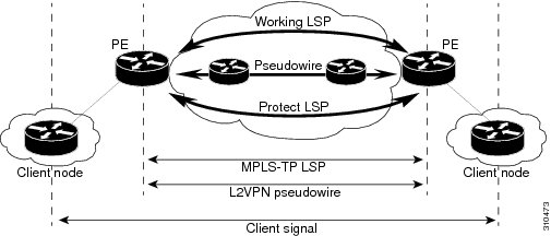
An MPLS–TP tunnel consists of a pair of unidirectional tunnels providing a bidirectional LSP. Each unidirectional tunnel can be protected with a protect LSP that activates automatically upon failure. MPLS–TP tunnels are provisioned manually at their endpoints across the network.
Tunnel Identifiers
MPLS–TP tunnel identifiers uniquely identify an MPLS–TP tunnel within the network. The tunnel identifier consists of a global identifier, a node identifier, and a tunnel number for each endpoint of the MPLS–TP LSP.
The node identifier is an IP address for an interface on the endpoint router. The tunnel number is the tunnel–tp number assigned when the tunnel–tp virtual interface is created on the endpoint router.
Tunnel Source
The tunnel source is the MPLS–TP node identifier of the endpoint router that is configured. This tunnel source can be specified to override the router-id configured in the global MPLS-TP configuration.
Tunnel Destination
The tunnel destination is the MPLS–TP node identifier of the remote endpoint router. The destination tunnel number is the virtual interface number assigned to the remote tunnel interface when it is provisioned. This destination tunnel number can be optionally configured. If the destination tunnel number is not configured, it defaults to the local tunnel number.
- Understanding MPLS–TP LSPs
- Tunnel Midpoints and Endpoints
- NTP-J41 Configure an MPLS-TP Tunnel
- DLP-J105 Configure Tunnel Midpoints Using Cisco IOS Commands
- DLP–J106 Configure Tunnel Endpoints Using Cisco IOS Commands
- DLP-J107 Create an MPLS–TP Tunnel Using CTC
- DLP-J208 Edit MPLS–TP Tunnel Attributes Using CTC
- DLP-J368 Query an MPLS-TP Circuit Using CTC
- NTP-J107 Perform ping and traceroute Operations on Services Using CTC
Understanding MPLS–TP LSPs
MPLS–TP LSPs are bidirectional and corouted and are comprised of two unidirectional LSPs that are supported by the MPLS forwarding infrastructure. The static and bidirectional MPLS–TP LSPs can be configured either through CTC or Cisco IOS commands. The LSPs are configured and managed without a control plane. The MPLS–TP LSPs have a fixed path. The statically defined LSP does not require an Interior Gateway Protocol (IGP).
MPLS–TP LSPs are not supported over a Link Aggregation Group (LAG). The static pseudowire is the only traffic carried over MPLS–TP LSPs in this release.
LSP Path Protection
MPLS–TP LSPs support 1:1 revertive path protection. The working and protect LSPs can be configured as part of configuring MPLS–TP tunnels. The working LSP is the primary LSP used to route the traffic. The protect LSP is a backup for the working LSP. When the working LSP fails, the traffic is switched to the protect LSP until the working LSP is restored, at which time the forwarding reverts to the working LSP.
LSP Number
The LSP number is assigned when the MPLS–TP LSP is configured. The default value of the LSP number is 0 for the working LSP and 1 for the protect LSP. You can edit LSP numbers.
LSP Ping and Trace
The LSP ping and trace commands are supported on MPLS–TP bidirectional LSPs and pseudowires.
LSP Lockout
The working LSP or protect LSP can be locked out. Only one LSP must be locked out at a time. When the LSP is currently locked out, the lockout command is not available in the other LSP configuration submode. The lockout of a working or protect LSP is cleared using the no lockout command.
When the LSP is locked out, the user traffic is not forwarded over the locked out LSP. However, the OAM traffic and BFD traffic is forwarded over the locked out LSP.
Because an MPLS-TP tunnel is statically configured, the possibility exists that the working LSP could be locked out at one MPLS-TP tunnel endpoint and the protect LSP could be locked out at the other MPLS-TP tunnel endpoint. If this occurs, the MPLS-TP tunnel is deadlocked and non-functional until the lockout configuration is changed at one of the endpoints.
Tunnel Midpoints and Endpoints
Tunnel LSPs, whether endpoint or midpoint, use the same identifying information. However, it is entered differently.
- At the midpoint, all the information for the LSP is specified with the mpls tp lsp command, which enters the submode for configuring forward and reverse information for forwarding.
- At the midpoint, determining which end is source and which end is destination is arbitrary. That is, if you are configuring a tunnel between your router and a coworker’s router, your router is the source. However, your coworker considers his or her router to be the source. At the midpoint, either router could be considered the source. At the midpoint, the forward direction is from source to destination, and the reverse direction is from destination to source.
- At the endpoint, the source information comes either from the global router ID or from locally configured information using the tp source command after you enter the command interface tunnel-tp number command, where number is the source tunnel number.
- At the endpoint, the remote information (destination) is configured using the tp destination command after you enter the command interface tunnel-tp number. The tp destination command includes the destination node ID, optionally the global ID, and optionally the destination tunnel number. If you do not specify the destination tunnel number, the source tunnel number is used.
- At the endpoint, the LSP number is configured in working-lsp or protect-lsp submode. The default value is 0 for the working LSP and 1 for the protect LSP.
NTP-J41 Configure an MPLS-TP Tunnel
Procedure
- DLP-J105 Configure Tunnel Midpoints Using Cisco IOS Commands
- DLP–J106 Configure Tunnel Endpoints Using Cisco IOS Commands
- DLP-J107 Create an MPLS–TP Tunnel Using CTC
- DLP-J208 Edit MPLS–TP Tunnel Attributes Using CTC
Stop. You have completed this procedure.
DLP-J105 Configure Tunnel Midpoints Using Cisco IOS Commands
Procedure
Command or Action Purpose
Step 1 enable
Example:Router> enableEnables privileged EXEC mode.
Step 2 configure terminal
Example:Router# configure terminalEnters global configuration mode.
Step 3 mpls tp lsp source ip-address [global-id number] tunnel-tp tunnelnumber lsp {lspnumber | working | protect} destination ip-address [global-id number] tunnel-tp tunnelnumber
Example:Router(config)# mpls tp lsp source 209.165.200.225 tunnel-tp 15 lsp 0 destination 209.165.200.226 tunnel-tp 20Configures the source and destination parameters of the MPLS–TP tunnel.
The source and destination parameters may be specified in a different order at different midpoints of an MPLS–TP tunnel. The default value of source and destination global–id is 0. The LSP number defined for one of the endpoints can uniquely identify an MPLS–TP LSP.
Step 4 forward–lsp
Example:Router(config-mpls-tp-lsp)# forward–lspEnters the configuration mode of the forward LSP.
Step 5 bandwidth number
Example:Router(config-mpls-tp-lsp-forw)# bandwidth 100Configures the bandwidth for the forward LSP.
The forward LSP refers to the unidirectional LSP going from the source to the destination.
Step 6 in–label locallabelnumber out-label outlabelnumber out-link outlinknumber
Example:Router(config-mpls-tp-lsp-forw)# in-label 200 out-label 300 out-link 2Assigns an incoming label (local label), outgoing label, and outgoing link to the forward LSP. The values for the incoming label must be within the static label range that is defined. The outgoing label must be a valid and unreserved MPLS label.
Step 7 exit
Example:Router(config-mpls-tp-lsp-forw)# exitExits the configuration mode of the forward LSP.
Step 8 reverse–lsp
Example:Router(config-mpls-tp-lsp)# reverse–lspEnters the configuration mode of the reverse LSP.
Step 9 bandwidth number
Example:Router(config-mpls-tp-lsp-rev)# bandwidth 100Configures the bandwidth for the reverse LSP.
The reverse LSP refers to the unidirectional LSP going from the destination to the source.
Step 10 in–label locallabelnumber out-label outlabelnumber out-link out-tp-link
Example:Router(config-mpls-tp-lsp-rev)# in-label 201 out-label 301 out-link 4Assigns an incoming label (local label), outgoing label, and outgoing link to the reverse LSP. The values for the incoming label must be within the static label range that is defined. The outgoing label must be a valid and unreserved MPLS label.
Step 11 exit
Example:Router(config-mpls-tp-lsp-rev)# exitExits the configuration mode of the reverse LSP.
Step 12 exit
Example:Router(config-mpls-tp-lsp)# exitExits the LSP configuration mode.
Step 13 Return to your originating procedure (NTP).
Example:—Example: Configuring Tunnel Midpoints
The following example shows how to configure the midpoints of the MPLS–TP tunnel using Cisco IOS commands:
Router> enable Router# configure terminal Router(config)# mpls label range 1000 8000 static 16 999 Router(config)# bfd bfd-tp-template Router(config)# mpls tp Router(config-mpls-tp)# router-id 2.2.2.2 Router(config-mpls-tp)# exit Router(config)# interface TenGigabitEthernet4/1 Router(config-if)# mpls tp link 1 ipv4 11.10.10.15 Router(config-if)# exit Router(config)# interface TenGigabitEthernet4/2 Router(config-if)# mpls tp link 1 ipv4 11.10.10.16 Router(config-if)# exit Router(config)# mpls tp lsp source 1.1.1.1 tunnel-tp 10 lsp working destination 3.3.3.3 tunnel-tp 30 Router(config-mpls-tp-lsp)# forward-lsp Router(config-mpls-tp-lsp-forw)# bandwidth 1000 Router(config-mpls-tp-lsp-forw)# in-label 200 out-label 300 out-link 2 Router(config-mpls-tp-lsp-forw)# exit Router(config-mpls-tp-lsp)# reverse-lsp Router(config-mpls-tp-lsp-rev)# in-label 250 out-label 100 out-link 1 Router(config-mpls-tp-lsp-rev)# exit Router(config-mpls-tp-lsp)# exit Router(config-mpls-tp)# exit Router(config)# mpls tp lsp source 1.1.1.1 tunnel-tp 10 lsp protect destination 3.3.3.3 tunnel-tp 30 Router(config-mpls-tp-lsp)# forward-lsp Router(config-mpls-tp-lsp-forw)# bandwidth 1000 Router(config-mpls-tp-lsp-forw)# in-label 201 out-label 301 out-link 4 Router(config-mpls-tp-lsp-forw)# exit Router(config-mpls-tp-lsp)# reverse-lsp Router(config-mpls-tp-lsp-rev)# in-label 251 out-label 101 out-link 3 Router(config-mpls-tp-lsp-rev)# exit Router(config-mpls-tp-lsp)# exit Router(config-mpls-tp)# exitDLP–J106 Configure Tunnel Endpoints Using Cisco IOS Commands
Procedure
Command or Action Purpose
Step 1 enable
Example:Router> enableEnables privileged EXEC mode.
Step 2 configure terminal
Example:Router# configure terminalEnters global configuration mode.
Step 3 interface tunnel–tp tunnelnumber
Example:Router(config)# interface tp–tunnel 30Enters the interface configuration mode and configures the parameters of the tunnel.
Step 4 description tunnel-description
Example:Router(config–if)# description firsttunnelProvides a description for the tunnel. The description is used only when displaying information about the MPLS–TP tunnel.
Step 5 bandwidth tx number [rx number]
Example:Router(config–if)# bandwidth tx 1000Configures the bandwidth for the MPLS–TP tunnel. The transmit and receive bandwidth provisioned for the working LSP are the same as that of the protect LSP.
Step 6 tp source ip-address [global-id number]
Example:Router(config–if)# tp source 209.165.200.225Configures the MPLS–TP tunnel source IP address. The source IP address is the ID of the endpoint router that is configured.
The global-id is the default global ID used for all midpoints and endpoints. The default value of the global–id is 0. The valid range is from 0 to 2147483647.
Step 7 tp destination ip-address [tunnel-tp number] [global-id number]
Example:Router(config–if)# tp destination 209.165.200.226Configures the MPLS–TP tunnel destination IP address.
The tunnel-tp is the tunnel–TP number of the MPLS–TP tunnel destination. If the tunnel–TP number is not specified, the number assigned to the local tunnel is used.
The global-id is the default global ID used for the endpoint. The default value of the global–id is 0. The valid range is from 0 to 2147483647.
Step 8 bfd bfdtemplatename
Example:Router(config–if)# bfd bfd1Configures a BFD template for the MPLS–TP tunnel. The BFD configuration template used for the working LSP is the same as that of the protect LSP.
Step 9 working-lsp
Example:Router(config–if)# working-lspEnters the configuration mode of the working LSP.
Step 10 out-label outlabelnumber out-link out-tp-link
Example:Router(config–if–working)# out–label 250 out–link 1Assigns an outgoing label and outgoing link to the working LSP. The outgoing label must be a valid and unreserved MPLS label.
The working LSP is the primary LSP that is used to route traffic.
Step 11 in–label locallabelnumber
Example:Router(config–if–working)# in–label 10Assigns an incoming label (local label) to the working LSP. The values for the incoming label must be within the static label range (16 to 8000).
Step 12 lsp–num number
Example:Router(config–if–working)# lsp–num 0Configures the LSP number for the working LSP.
The default LSP number for the working LSP is 0. The range is 0 and above. The local and remote LSP numbers must match.
Step 13 lockout
Example:Router(config–if–working)# lockoutLocks out the working LSP.
Step 14 protect-lsp
Example:Router(config–if)# protect-lspEnters the configuration mode of the protect LSP.
Step 15 out-label outlabelnumber out-link out-tp-link
Example:Router(config–if–protect)# out–label 251 out–link 2Assigns an outgoing label and outgoing link to the protect LSP. The outgoing label must be a valid and unreserved MPLS label.
A protect LSP is a backup for a working LSP. If the working LSP fails, the traffic is switched to the protect LSP until the working LSP is restored, when forwarding reverts to the working LSP.
Step 16 in–label locallabelnumber
Example:Router(config–if–protect)# in–label 20Assigns an incoming label (local label) to the protect LSP. The values for the incoming label must be within the static label range that is defined.
Step 17 lsp–num number
Example:Router(config–if–protect)# lsp–num 1Configures the LSP number for the protect LSP.
The default LSP number for the protect LSP is 1. The range is 1 and above. The local and remote LSP numbers must match.
Step 18 lockout
Example:Router(config–if–protect)# lockoutLocks out the protect LSP.
Step 19 shutdown
Example:Router(config–if)# shutdownPerforms an administrative shut down of the MPLS–TP tunnel.
Step 20 Return to your originating procedure (NTP). Example: Configuring Tunnel Endpoints
The following example shows how to configure one of the endpoints of the MPLS–TP tunnel using Cisco IOS commands:
Router> enable
Router# configure terminal
Router(config)# mpls label range 1000 8000 static 16 999
Router(config)# bfd bfd-tp-template

Router(config)# mpls tp
Router(config-mpls-tp)# router-id 1.1.1.1
Router(config-mpls-tp)# exit

Router(config)# interface TenGigabitEthernet4/1
Router(config-if)# mpls tp link 1 ipv4 11.10.10.15
Router(config-if)# exit
Router(config)# interface TenGigabitEthernet4/2
Router(config-if)# mpls tp link 1 ipv4 11.10.10.16
Router(config-if)# exit

Router(config)# interface tunnel–tp 10
Router(config-if)# description MPLS-TP tunnel connecting ABC customer A PE routers
Router(config–if)# bandwidth  tx 1000

Router(config-if)# no ip address
Router(config-if)# no keepalive
Router(config-if)# tp destination 3.3.3.3 tunnel-tp 30
Router(config-if)# bfd  bfd-tp-template

Router(config-if)# working-lsp
Router(config-if-working)# out-label 200 out-link 1
Router(config-if-working)# in-label 100
Router(config-if-working)# lsp-number 0
Router(config-if-working)# exit

Router(config-if)# protect-lsp
Router(config-if-protect)# out-label 201 out-link 2
Router(config-if-protect)# in-label 101
Router(config-if-protect)# lsp-number 1
Router(config-if-protect)# exit
Router(config-if)# exit
The following example shows how to configure another endpoint of the MPLS–TP tunnel using Cisco IOS commands:
Router> enable
Router# configure terminal
Router(config)# mpls label range 1000 8000 static 16 999
Router(config)# bfd bfd-tp-template

Router(config)# mpls tp
Router(config-mpls-tp)# router-id 2.2.2.2
Router(config-mpls-tp)# exit

Router(config)# interface TenGigabitEthernet4/3
Router(config-if)# mpls tp link 1 ipv4 11.10.11.17
Router(config-if)# exit
Router(config)# interface TenGigabitEthernet4/4
Router(config-if)# mpls tp link 1 ipv4 11.10.11.18
Router(config-if)# exit

Router(config)# interface tunnel–tp 30
Router(config-if)# description  MPLS-TP tunnel connecting ABC customer A PE routers
Router(config–if)# bandwidth  tx 1500

Router(config-if)# no ip address
Router(config-if)# no keepalive
Router(config-if)# tp destination 1.1.1.1 tunnel-tp 10
Router(config-if)# bfd  bfd-tp-template

Router(config-if)# working-lsp
Router(config-if-working)# out-label 250 out-link  1 in-label 300
Router(config-if-working)# lsp-number 2
Router(config-if-working)# exit

Router(config-if)# protect-lsp
Router(config-if-protect)# out-label 251 out-link 2 in-label 301
Router(config-if-working)# lsp-number 3
Router(config-if-protect)# exit
Router(config-if)# exit
DLP-J107 Create an MPLS–TP Tunnel Using CTC
Procedure
Purpose This procedure creates an MPLS–TP tunnel using CTC.
Tools/Equipment None Prerequisite Procedures Required/As Needed As needed Onsite/Remote Onsite or remote Security Level Provisioning or higher
Note
You cannot create an MPLS–TE tunnel and an MPLS–TP tunnel on the same interface.
Note
The layer 2 services on CPT can be created on top of layer 2 PPCs or OCHTrails.
CPT supports Client/Trunk to Client/Trunk (layer 2) PPC for topology discovery and layer 2 service routing. If CPT is used in the GNE-ENE mode of configuration, then generic communications channels (GCC) can be used for topology discovery and layer 2 PPCs for layer 2 service routing. Both layer 2 PPC and GCC can be created between the same set of ports. However, this is not mandatory.
CPT also supports OCH Trunk to OCH Filter PPCs to connect CPT to MSTP nodes. If you want to route the traffic from a non co-located CPT node to a DWDM network, use OCH Trunk to OCH Filter PPCs to connect CPT and MSTP nodes. The OCHTrail can be created on top of this and the layer 2 services can be created on top of OCHTrails.
Step 1 Complete the NTP-J22 Log into CTC procedure at a node on the network where you want to create an MPLS–TP tunnel. Step 2 From the View menu, choose Go to Network View. Step 3 Click the Layer2+ tab. Step 4 In the left pane, click Circuits. Step 5 Click the MPLS TP Tunnels tab. Step 6 Click Create. The Circuit Creation wizard appears. Step 7 In the Circuit Attributes screen of the wizard:
Step 8 In the Source screen of the wizard, specify the parameters for one endpoint:
Step 9 In the Destination screen of the wizard, specify the parameters for another endpoint. Repeat the previous step to do this. Step 10 In the TP Tunnel Circuit Routing Preferences screen of the wizard, specify the routing preferences for the tunnel:
Step 11 In the TP Tunnel Circuit Routing Constraints screen of the wizard, the route of the MPLS–TP tunnel is displayed. Step 12 In the TP Tunnel Circuit Label Preview screen of the wizard:
Step 13 Return to your originating procedure (NTP).
DLP-J208 Edit MPLS–TP Tunnel Attributes Using CTC
Procedure
Purpose This procedure edits MPLS–TP tunnel attributes using CTC. Tools/Equipment None Prerequisite Procedures DLP-J107 Create an MPLS–TP Tunnel Using CTC Required/As Needed As needed Onsite/Remote Onsite or remote Security Level Provisioning or higher
Step 1 Complete the NTP-J22 Log into CTC procedure at a node on the network where you want to edit an MPLS–TP tunnel. Step 2 From the View menu, choose Go to Network View. Step 3 Click the Layer2+ tab. Step 4 From the left pane, click Circuits. Step 5 Click the MPLS TP Tunnels tab. Step 6 Choose a tunnel to edit and click Edit. The Edit Circuit screen appears. Step 7 In the General tab, modify the name, description of the MPLS–TP tunnel as required. Step 8 In the LSPs tab, edit, add, or remove the LSPs:
Step 9 In the BFD tab, choose an appropriate BFD template from the BFD Template field and click Apply. Step 10 In the Lockout tab, choose a node from the Endpoint field. Step 11 From the Switch State drop–down list, choose LOCKOUT or CLEAR The Lockout option specifies that the locked out LSP do not carry traffic. Only one LSP can be locked out at a time. The Lockout option can be applied only when there are two LSPs. The Clear option clears the lockout condition. Step 12 In the State tab, choose UP or DOWN from the Target Circuit Admin State drop-down list and click Apply. Step 13 Return to your originating procedure (NTP).
DLP-J368 Query an MPLS-TP Circuit Using CTC
Procedure
Purpose This procedure allows you to discover the MPLS-TP services using CTC.
Tools/Equipment None Prerequisite Procedures DLP-J107 Create an MPLS–TP Tunnel Using CTC Required/As Needed As needed Onsite/Remote Onsite or remote Security Level Provisioning or higher
NoteWhen the discovered nodes are disconnected, the circuits move to Partial state. When the disconnected nodes become online in CTC, re-query the circuits to move the circuits to Discovered state.
Step 1 Complete the NTP-J22 Log into CTC procedure at a node where you want to query for an MPLS-TP circuit. Step 2 From the View menu, choose Go to Home View. Step 3 Click the Layer2+ tab. Step 4 From the left pane, click Carrier Ethernet. Step 5 Click Query. The L2 Services Query dialog box appears. Step 6 From the Existing/New Query drop-down list, choose an existing query or a new query. Step 7 In the Equipment Termination area, choose Port or Query Group. Step 8 If you choose Port, specify the following: Step 9 If you choose Query Group, specify the following:
- Click Query Group. The User Query Group Chooser dialog box appears.
- From the Group drop-down list, choose a query group.
- Add the nodes that can be grouped for the query from the Available Nodes area to the Grouped Nodes area.
- Click Save to save the query group and close the User Query Group Chooser dialog box.
Step 10 In the L2 Services Query dialog box, click Save. The Store a Set of Query Criteria dialog box appears. Step 11 Enter the query name in the Name field and click Save to save the query. Step 12 In the L2 Services Query dialog box, click Run Query. The results of the query appear in the Service Query Results area.
Step 13 Click Discover All to discover all the MPLS-TP services, click Discover Selected to discover the selected MPLS-TP services or click Delete to delete the midpoint nodes of the MPLS-TP services. Close the L2 Services Query dialog box. The discovered MPLS-TP services appear in the Carrier Ethernet Circuits area.
Step 14 Return to your originating procedure (NTP).
NTP-J107 Perform ping and traceroute Operations on Services Using CTC
Procedure
Step 1 Complete the NTP-J22 Log into CTC procedure at a node on the network where you want to perform ping and traceroute operations. Step 2 Right-click the fabric or line card and choose Open Packet Transport System View. The Packet Transport System View dialog box appears. Step 3 Click the Maintenance tab. Step 4 In the left pane, click OAM. Step 5 From the Service drop-down list, choose TP Tunnel, TE Tunnel, Pseudowire. Step 6 From the Command drop-down list, choose Ping or Traceroute. Step 7 If you choose TP Tunnel as the service, complete the following: Step 8 If you choose TE Tunnel as the service, complete the following: Step 9 If you choose Pseudowire as the service, complete the following: Step 10 Click Execute to run the OAM operation for the specified service. Stop. You have completed this procedure.
MPLS–TP Show Commands
This section describes several show commands that can be used with MPLS–TP tunnels.
Display MPLS–TP Tunnel Summary
This command displays a count of the configured tunnels, midpoint LSPs, and the global configuration parameters.
Router# show mpls tp summaryEndpoints: 4 Midpoints: 3 ICC: Router Id: 3.3.3.3 Global Id: 0 Path protection mode: 1:1 revertive Fault OAM timer: 0Display Link Number Information
This command provides information about the MPLS–TP link numbers. It displays the mappings between link numbers and physical interfaces and next hop addresses when appropriate.
Router# show mpls tp link-numbersLink Number Interface Next Hop 1 Ethernet0/0 1.2.3.4 2 Ethernet1/0 2.3.4.5 3 Ethernet0/3 fcce.c1cc.cc01Display MPLS–TP Tunnel Information
This command displays the tunnel information of MPLS–TP tunnels.
Router# show mpls tp tunnel-tpTunnel Peer node-id::tun Working/ Local Outgoing Outgoing Oper Number Protect Label Label Interface State 5 4.4.4.4::5 w 100 110 Et0/0 up 6 6.6.6.6::7 w 200 210 Et0/0 upDisplay MPLS–TP Tunnel Information with LSPs
This command displays the tunnel information of MPLS–TP tunnels with LSPs.
Router# show mpls tp tunnel-tp lspsTunnel Peer node-id::tun Working/ Local Outgoing Outgoing Oper Number Protect Label Label Interface State 5 4.4.4.4::5 w 100 110 Et0/0 up LSP: working 100 110 Et0/0 up active LSP: protect 120 130 Et1/0 up standby 6 6.6.6.6::7 w 200 210 Et0/0 up LSP: working 200 210 Et0/0 up active LSP: protect 220 230 Et1/0 up standbyDisplay Detailed MPLS–TP Tunnel Information
This command displays detailed tunnel information of MPLS–TP tunnels.
Router# show mpls tp tunnel-tp detailMPLS-TP Tunnels: MPLS-TP tunnel 5: source global id 0 : node id 3.3.3.3 : tunnel 5 dest global id 0 : node id 4.4.4.4 : tunnel 5 description: this is test tunnel 5 UMC: tunnel5 ICC: ATT Admin: up Oper: up bandwidth transmit 1400, receive 1500 BFD template: bfd-template-5 working-lsp: active lsp num 0 protect-lsp: standby lsp num 1 MPLS-TP tunnel 6: source global id 0 : node id 3.3.3.3 : tunnel 6 dest global id 0 : node id 6.6.6.6 : tunnel 7 description: this is test tunnel 6 Admin: up Oper: up bandwidth transmit 1600, receive 1700 BFD template: working-lsp: active lsp num 0 protect-lsp: standby lsp num 1 MPLS-TP tunnel 65530: source global id 0 : node id 123.123.123.123 : tunnel 65530 dest global id 0 : node id 124.124.124.124 : tunnel 65530 description: this is test tunnel 65530 UMC: big_id Admin: up Oper: up bandwidth transmit 1600, receive 1700 BFD template: working-lsp: active lsp num 0 protect-lsp: standby lsp num 1Display Detailed MPLS–TP Tunnel Information with LSPs
This command displays detailed tunnel information of MPLS–TP tunnels with LSPs.
Router# show mpls tp tunnel-tp lsps detailMPLS-TP Tunnels: MPLS-TP tunnel 5: source global id 0 : node id 3.3.3.3 : tunnel 5 dest global id 0 : node id 4.4.4.4 : tunnel 5 description: this is test tunnel 5 UMC: tunnel5 ICC: ATT Admin: up Oper: up bandwidth transmit 1400, receive 1500 BFD template: bfd-template-5 working-lsp: active lsp num 0 0::3.3.3.3::5::0::4.4.4.4::5::0 local label 100 local label table 0 outgoing label 110 outgoing tp-link 1 interface Et0/0 UMC: working-5 protect-lsp: standby lsp num 1 0::3.3.3.3::5::0::4.4.4.4::5::1 local label 120 local label table 0 outgoing label 130 outgoing tp-link 2 interface Et1/0 MPLS-TP tunnel 6: source global id 0 : node id 3.3.3.3 : tunnel 6 dest global id 0 : node id 6.6.6.6 : tunnel 7 description: this is test tunnel 6 Admin: up Oper: up bandwidth transmit 1600, receive 1700 BFD template: working-lsp: active lsp num 0 0::3.3.3.3::6::0::6.6.6.6::7::0 local label 200 local label table 0 outgoing label 210 outgoing tp-link 1 interface Et0/0 protect-lsp: standby lsp num 1 0::3.3.3.3::6::0::6.6.6.6::7::1 local label 220 local label table 0 outgoing label 230 outgoing tp-link 2 interface Et1/0 UMC: protect-6 MPLS-TP tunnel 65530: source global id 0 : node id 123.123.123.123 : tunnel 65530 dest global id 0 : node id 124.124.124.124 : tunnel 65530 description: this is test tunnel 65530 UMC: big_id Admin: up Oper: up bandwidth transmit 1600, receive 1700 BFD template: working-lsp: active lsp num 0 0::123.123.123.123::65530::0::124.124.124.124::65530::0 local label 300 local label table 0 outgoing label 310 outgoing tp-link 1 interface Et0/0 protect-lsp: standby lsp num 1 0::123.123.123.123::65530::0::124.124.124.124::65530::1 local label 320 local label table 0 outgoing label 330 outgoing tp-link 2 interface Et1/0Display MPLS–TP Tunnel Information for a Single Tunnel
This command displays the tunnel information for a single MPLS–TP tunnel.
Router# show mpls tp tunnel-tp tunnelnumberTunnel Peer node-id::tun Working/ Local Outgoing Outgoing Oper Number Protect Label Label Interface State 5 4.4.4.4::5 w 100 110 Et0/0 upDisplay MPLS–TP Tunnel Information for a Single Tunnel with LSPs
This command displays the tunnel information for a single MPLS–TP tunnel with LSPs.
Router# show mpls tp tunnel-tp tunnelnumber lspsTunnel Peer node-id::tun Working/ Local Outgoing Outgoing Oper Number Protect Label Label Interface State 5 4.4.4.4::5 w 100 110 Et0/0 up LSP: working 100 110 Et0/0 up active LSP: protect 120 130 Et1/0 up standby 6 6.6.6.6::7 w 200 210 Et0/0 up LSP: working 200 210 Et0/0 up active LSP: protect 220 230 Et1/0 up standbyDisplay Detailed MPLS–TP Tunnel Information for a Single Tunnel
This command displays the detailed tunnel information for a single MPLS–TP tunnel.
Router# show mpls tp tunnel-tp tunnelnumber detailMPLS-TP Tunnels: MPLS-TP tunnel 5: source global id 0 : node id 3.3.3.3 : tunnel 5 dest global id 0 : node id 4.4.4.4 : tunnel 5 description: this is test tunnel 5 UMC: tunnel5 ICC: ATT Admin: up Oper: up bandwidth transmit 1400, receive 1500 BFD template: bfd-template-5 working-lsp: active lsp num 0 protect-lsp: standby lsp num 1Display Detailed MPLS–TP Tunnel Information for a Single Tunnel with LSPs
This command displays the detailed tunnel information for a single MPLS–TP tunnel with LSPs.
Router# show mpls tp tunnel-tp tunnelnumber lsps detailMPLS-TP Tunnels: MPLS-TP tunnel 5: source global id 0 : node id 3.3.3.3 : tunnel 5 dest global id 0 : node id 4.4.4.4 : tunnel 5 description: this is test tunnel 5 UMC: tunnel5 ICC: ATT Admin: up Oper: up bandwidth transmit 1400, receive 1500 BFD template: bfd-template-5 working-lsp: active lsp num 0 0::3.3.3.3::5::0::4.4.4.4::5::0 local label 100 local label table 0 outgoing label 110 outgoing tp-link 1 interface Et0/0 UMC: working-5 protect-lsp: standby lsp num 1 0::3.3.3.3::5::0::4.4.4.4::5::1 local label 120 local label table 0 outgoing label 130 outgoing tp-link 2 interface Et1/0Display LSP Information
This command displays information for all the MPLS–TP LSPs (midpoint and endpoint LSPs) configured on this router.
Router# show mpls tp lspsMPLS-TP Endpoint LSPs: LSP Identifier Local Outgoing Outgoing Oper Role Label Label Interface State 0::3.3.3.3::5::0::4.4.4.4::5::0 100 110 Et0/0 up active 0::3.3.3.3::5::0::4.4.4.4::5::1 120 130 Et1/0 up standby 0::3.3.3.3::6::0::6.6.6.6::7::0 200 210 Et0/0 up active 0::3.3.3.3::6::0::6.6.6.6::7::1 220 230 Et1/0 up standby MPLS-TP Midpoint LSPs: LSP Identifier LSP Local Outgoing Outgoing Label Label Interface 0::1.1.1.1::1::0::6.6.6.6::1::0 forw 150 151 Et0/0 rev 152 153 Et1/0 0::1.1.1.1::9::0::9.9.9.9::9::0 forw 160 161 Et0/0 rev 162 163 Et1/0Display Midpoint LSP Information
This command displays information for the midpoint LSP.
Router# show mpls tp lsps midpointsMPLS-TP Midpoint LSPs: LSP Identifier LSP Local Outgoing Outgoing Label Label Interface 0::1.1.1.1::1::0::6.6.6.6::1::0 forw 150 151 Et0/0 rev 152 153 Et1/0 0::1.1.1.1::9::0::9.9.9.9::9::0 forw 160 161 Et0/0 rev 162 163 Et1/0Display Endpoint LSP Information
This command displays information for the endpoint LSP.
Router# show mpls tp lsps endpointsMPLS-TP Endpoint LSPs: LSP Identifier Local Outgoing Outgoing Oper Role Label Label Interface State 0::3.3.3.3::5::0::4.4.4.4::5::0 100 110 Et0/0 up active 0::3.3.3.3::5::0::4.4.4.4::5::1 120 130 Et1/0 up standby 0::3.3.3.3::6::0::6.6.6.6::7::0 200 210 Et0/0 up active 0::3.3.3.3::6::0::6.6.6.6::7::1 220 230 Et1/0 up standbyDisplay Detailed LSP Information
This command displays detailed LSP information.
Router# show mpls tp lsps detailMPLS-TP Endpoint LSPs: 0::3.3.3.3::5::0::4.4.4.4::5::0 local label 100 local label table 0 outgoing label 110 outgoing tp-link 1 interface Et0/0 UMC: working-5 0::3.3.3.3::5::0::4.4.4.4::5::1 local label 120 local label table 0 outgoing label 130 outgoing tp-link 2 interface Et1/0 0::3.3.3.3::6::0::6.6.6.6::7::0 local label 200 local label table 0 outgoing label 210 outgoing tp-link 1 interface Et0/0 0::3.3.3.3::6::0::6.6.6.6::7::1 local label 220 local label table 0 outgoing label 230 outgoing tp-link 2 interface Et1/0 UMC: protect-6 0::123.123.123.123::65530::0::124.124.124.124::65530::0 local label 300 local label table 0 outgoing label 310 outgoing tp-link 1 interface Et0/0 0::123.123.123.123::65530::0::124.124.124.124::65530::1 local label 320 local label table 0 outgoing label 330 outgoing tp-link 2 interface Et1/0 MPLS-TP Midpoint LSPs: 0::1.1.1.1::1::0::6.6.6.6::1::0 source global id 0 : node id 1.1.1.1 : tunnel 1 dest global id 0 : node id 6.6.6.6 : tunnel 1 lsp working UMC: midpoint_1_2 ICC: ATT forward-lsp: local label 150 outgoing label 151 outgoing tp-link 1 interface Et0/0 bandwidth 1122 reverse-lsp: local label 152 outgoing label 153 outgoing tp-link 2 inteface Et1/0 bandwidth 2211 0::1.1.1.1::9::0::9.9.9.9::9::0 source global id 0 : node id 1.1.1.1 : tunnel 9 dest global id 0 : node id 9.9.9.9 : tunnel 9 lsp working forward-lsp: local label 160 outgoing label 161 outgoing tp-link 1 interface Et0/0 bandwidth 0 reverse-lsp: local label 162 outgoing label 163 outgoing tp-link 2 inteface Et1/0 bandwidth 0 0::2.2.2.2::2::0::9.9.9.9::2::0 source global id 0 : node id 2.2.2.2 : tunnel 2 dest global id 0 : node id 9.9.9.9 : tunnel 2 lsp working forward-lsp: local label 170 outgoing label 171 outgoing tp-link 1 interface Et0/0 bandwidth 0 reverse-lsp: local label 172 outgoing label 173 outgoing tp-link 2 inteface Et1/0 bandwidth 0Display Matching LSP Information
This command displays information for the MPLS–TP LSPs that match the specified filter value. The filter value can be node-id, global-id, tunnel number, or lsp number. The specified filter value is applied to each source and destination LSP identifier.
Router# show mpls tp lsps 6.6.6.6MPLS-TP Endpoint LSPs: LSP Identifier Local Outgoing Outgoing Oper Role Label Label Interface State 0::3.3.3.3::6::0::6.6.6.6::7::0 200 210 Et0/0 up active 0::3.3.3.3::6::0::6.6.6.6::7::1 220 230 Et1/0 up standby MPLS-TP Midpoint LSPs: LSP Identifier LSP Local Outgoing Outgoing Label Label Interface 0::1.1.1.1::1::0::6.6.6.6::1::0 forw 150 151 Et0/0 rev 152 153 Et1/0