-
Cisco CPT Configuration Guide–CTC and Documentation Release 9.3 and Cisco IOS Release 15.1(01)SA
-
Preface
-
Understanding the Carrier Packet Transport System
-
Hardware
-
Configuring Ethernet Virtual Circuit
-
Configuring Multiprotocol Label Switching
-
Configuring MPLS–Transport Profile
-
Configuring Pseudowire
-
Configuring Quality of Service
-
Configuring High Availability
-
Configuring Resilient Ethernet Protocol
-
Configuring Link Aggregation Group and Link Aggregation Control Protocol
-
Configuring MAC Learning
-
Configuring Multicast VLAN Registration
-
Configuring IGMP Snooping
-
Configuring Performance Monitoring, RMON, OTN, and Port Provisioning
-
Configuring Local Authentication
-
Configuring Cisco Discovery Protocol
-
Alarm Troubleshooting
-
SNMP
-
CPT Error Messages
-
Network Element Defaults
-
Index
-
 Feedback
Contents
- Configuring Quality of Service
- Introduction to Quality of Service
- Advantages of QoS
- Understanding QoS
- CPT System QoS
- NTP-J62 Configuring QoS Features Using Cisco IOS Commands
- NTP-J63 Configuring QoS Features Using CTC
- Ingress QoS Functions
- Ingress Classification
- DLP-J190 Configuring Ingress Classification Using Cisco IOS Commands
- DLP-J191 Creating or Editing a Class Map Using CTC
- Ingress Policing
- DLP-J192 Configuring Ingress Policing Using Cisco IOS Commands
- DLP-J193 Creating or Editing a Policy Map Using CTC
- DLP-J194 Setting Policy Class Actions Using CTC
- DLP-J195 Attaching or Removing a Traffic Policy from the Target Using Cisco IOS Commands
- DLP-J196 Attaching or Removing a Traffic Policy from the Target Using CTC
- Ingress Marking
- DLP-J197 Configuring Ingress Marking Using Cisco IOS Commands
- Egress QoS Functions
- Egress Classification
- DLP-J199 Configuring Egress Classification Using Cisco IOS Commands
- Egress Marking
- DLP-J207 Configuring Table Maps for Egress Marking Using Cisco IOS Commands
- DLP-J200 Associating Table Maps at Egress Using Cisco IOS Commands
- DLP-J198 Creating or Editing a Table Map Using CTC
- Egress Queue Scheduling
- Egress LLQ
- DLP-J201 Configuring Egress LLQ Using Cisco IOS Commands
- Egress Bandwidth
- DLP-J202 Configuring Egress Bandwidth Using Cisco IOS Commands
- Egress Shaping
- DLP-J203 Configuring Egress Shaping Using Cisco IOS Commands
- Egress Bandwidth Remaining Ratio and Bandwidth Remaining Percent
- DLP-J204 Configuring Egress Bandwidth Remaining Ratio or Bandwidth Remaining Percent Using Cisco IOS Commands
- DLP-J205 Monitoring and Verifying QoS Configuration Using Cisco IOS Commands
- DLP-J206 Monitoring and Verifying QoS Configuration Using CTC
- NTP-J66 Load or Store Class Maps, Table Maps, or Policy Maps Using CTC
- Understanding Multicast QoS
- Hierarchical QoS
- EVCS QoS Support
- QoS Support on Port-Channel
- QoS Statistics
- Retrieving Egress QoS Statistics
- QoS Configuration Guidelines for the Cisco CPT 50 Shelf
- Interlink QoS
Configuring Quality of Service
This chapter describes the Quality of Service and procedures to configure Quality of Service.
- Introduction to Quality of Service
- CPT System QoS
- Ingress QoS Functions
- Egress QoS Functions
- Understanding Multicast QoS
- Hierarchical QoS
- EVCS QoS Support
- QoS Support on Port-Channel
- QoS Statistics
- Retrieving Egress QoS Statistics
- QoS Configuration Guidelines for the Cisco CPT 50 Shelf
- Interlink QoS
Introduction to Quality of Service
The Cisco Carrier Packet Transport (CPT) system is a Carrier Ethernet based crossponder solution used as an access or an aggregation device. To maximize the utility of network bandwidth, service providers can aggregate different types of traffic (voice, video, broadband data, and so on) and transmit them over the network. Because a single device supports a wide range of traffic (voice, video, broadband data, and so on), it is important to distinguish traffic from one another and provide differential services.
Quality of Service (QoS) refers to the ability of a network to provide improved services to selected network traffic over various underlying technologies including Ethernet and IEEE 802.1 networks, and MPLS networks.
The Cisco CPT system can be configured to provide different levels of treatment to different services. The different levels are defined through the service elements of bandwidth, including loss and delay. A service-level agreement (SLA) is a guaranteed level of these service elements. The CPT system supports flat and hierarchical QoS up to three levels.
You configure QoS throughout a network to provide an end-to-end QoS delivery. The following two components are necessary to deliver QoS across a heterogeneous network:
Advantages of QoS
Enabling QoS in the network has the following advantages:
- Control over resources—You can control resources like bandwidth that is being used.
- Tailored services—If you are a service provider, the control and visibility that QoS provides enable you to offer carefully tailored grades of service differentiation to your customers.
- Coexistence of mission-critical applications:
- Your WAN is used efficiently by mission-critical applications that are most important to your business.
- Bandwidth and minimum delays required by time-sensitive multimedia and voice applications are available.
- Other applications using the link get their fair service without interfering with mission-critical traffic.
Understanding QoS
The QoS mechanism has three basic steps. It classifies types of traffic, specifies what action to take against a type of traffic, and specifies where the action should take place. The following sections explain how the CPT system accomplishes these steps.
Classification Mechanism for IP, Ethernet, and MPLS
For any QoS service to be applied to data, there must be a way to classify an IP packet or an Ethernet frame. When identified, a specific priority can be assigned to each individual IP packet or Ethernet frame. The IP Precedence field or the IP Differentiated Services Code Point (DSCP) field can be used to classify IP packets, and the Ethernet class of service (IEEE 802.1p defined class of service [CoS]) can be used for classifying Ethernet frames. IP precedence, IP DSCP, Ethernet CoS, and MPLS EXP are further described in the following sections.
IP Precedence
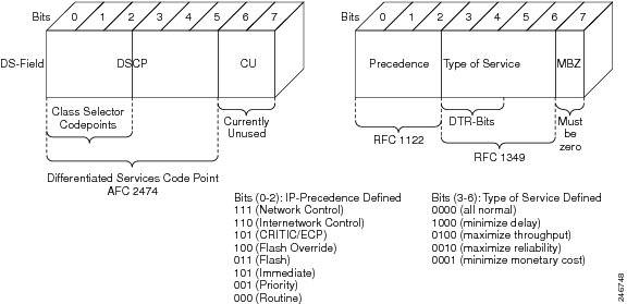
Use of IP precedence enables you to specify the class of service (CoS) for a packet using the three precedence bits in the type of service (ToS) field of the IP version 4 (IPv4) header. By default, each precedence corresponds to a name. These names, which continue to evolve, are defined in RFC 791.
Number Name 0 routine 1 priority 2 immediate 3 flash 4 flash-override 5 critical 6 internet 7 networks
NoteIP precedence bit settings 6 and 7 are reserved for network control information, such as routing updates.
IP Differentiated Services Code Point
IP DSCP uses the six bits in the IPv4 header to specify class of service for each IP packet (IETF RFC 2474). The DSCP field classifies packets into any of the 64 possible classes. On the network edge, the IP DSCP is assigned by the client device or the router, so that each subsequent network element can provide services based on the determined policy or the SLA.
Ethernet CoS
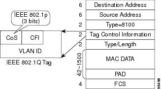
 The Ethernet CoS refers to the three bits within a four byte IEEE 802.1Q (VLAN) header used to indicate the priority of the Ethernet frame as it passes through a switched network. The CoS bits in the IEEE 802.1Q header are commonly referred to as the IEEE 802.1p bits. There are three CoS bits that provide eight classes, matching the IP precedence number. In many real-world networks, a packet might traverse both Layer 2 and Layer 3 domains. To maintain QoS across the network, the IP ToS can be mapped to the Ethernet CoS and vice versa. For example, in a linear or one-to-one mapping where each mechanism supports eight classes. Similarly, a set of DSCP values (64 classes) can be mapped into each of the eight individual Ethernet CoS values. An IEEE 802.1Q Ethernet frame, which consists of a 2-byte Ethertype and a 2-byte tag (IEEE 802.1Q tag) on the Ethernet protocol header is shown in this figure.
Multiprotocol Label Switching Experimental
The Multiprotocol Label Switching (MPLS) Experimental (EXP) is a 3-bit field and part of the Multiprotocol Label Switching (MPLS) header. It was created by the IETF on an experimental basis, but later became part of the standard MPLS header. The EXP bits in the MPLS header carry the packet priority. Each label switch router (LSR) along the path honors the packet priority by queuing the packet into the proper queue and servicing the packet accordingly.
CPT System QoS
The CPT system QoS classifies each packet in the network based on its Ethernet CoS, IP precedence, IP DSCP, MPLS EXP bits. After they are classified into class flows, further QoS functions can be applied to each packet as it traverses the CPT system.
The policing feature of the CPT system ensures that the attached equipment does not submit more than a predefined amount of bandwidth (Rate Limiting) into the network. The policing feature can be used to enforce the committed information rate (CIR) and the peak information rate (PIR) available to a customer at an interface. The policing action is applied per classification.
The marking feature can set the Ethernet CoS, IP precedence, or IP DSCP bits when packets enter the CPT system. For MPLS traffic, marking sets the MPLS EXP bits when the packets leave the system. The marking feature operates on the outer IEEE 802.1p tag, IP precedence, or IP DSCP bits and provides a mechanism for tagging packets at the ingress; and on the MPLS EXP bits at the egress by using table-maps. The subsequent network elements can provide a QoS based only the QoS indicator that the service provider has created.
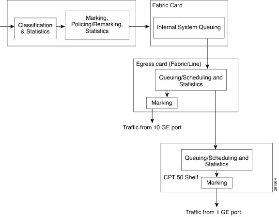
The per-class queuing allows various queuing applications to support SLA. For example, allocation of committed information rate, ensuring low latencies and rate limiting traffic to down stream nodes based on the configuration, and also enabling fair access to excess network bandwidth. The CPT system uses a combination of Strict Priority Queuing (SPQ) and Weighted Round Robin (WRR) scheduling process to guarantee throughput and latency requirements and to provide fair access to excess bandwidth. The CPT system QoS flow is illustrated in this figure.NTP-J62 Configuring QoS Features Using Cisco IOS Commands
Procedure
Purpose This procedure configures QoS features using IOS commands. Tools/Equipment None Prerequisite Procedures None Required/As Needed As needed Onsite/Remote Remote Security Level None
NoteUsers can create traffic policies and attach these policies to targets. A traffic policy contains a traffic class and one or more QoS features. A traffic class is used to classify traffic, while the QoS features in the traffic policy determine how to treat the classified traffic.
Step 1 Define a traffic class using the class-map command:
- To configure traffic classification at the ingress, see DLP-J190 Configuring Ingress Classification Using Cisco IOS Commands.
- To configure traffic classification at the egress, see DLP-J199 Configuring Egress Classification Using Cisco IOS Commands.
Step 2 Create a traffic policy using the policy-map command to associate the traffic class with one or more QoS features (using the policy-map command):
- To configure policing at the ingress, see DLP-J192 Configuring Ingress Policing Using Cisco IOS Commands.
- To configure marking at the ingress, see DLP-J197 Configuring Ingress Marking Using Cisco IOS Commands.
- To configure marking at the egress using table maps, see DLP-J207 Configuring Table Maps for Egress Marking Using Cisco IOS Commands.
- To associate table maps at the egress using table maps, see DLP-J200 Associating Table Maps at Egress Using Cisco IOS Commands.
- To configure shaping at the egress, see DLP-J203 Configuring Egress Shaping Using Cisco IOS Commands.
- To configure the egress bandwidth, see DLP-J202 Configuring Egress Bandwidth Using Cisco IOS Commands.
- To configure low-latency queuing (LLQ), see DLP-J201 Configuring Egress LLQ Using Cisco IOS Commands.
- To configure bandwidth remaining ratio (BRR) or bandwidth remaining percent (BRP), see DLP-J204 Configuring Egress Bandwidth Remaining Ratio or Bandwidth Remaining Percent Using Cisco IOS Commands.
Step 3 Attach the traffic policy to the target using the service-policy command, see DLP-J195 Attaching or Removing a Traffic Policy from the Target Using Cisco IOS Commands. Step 4 Monitor and verify the QoS configuration. See DLP-J205 Monitoring and Verifying QoS Configuration Using Cisco IOS Commands.
NTP-J63 Configuring QoS Features Using CTC
Procedure
Step 1 Create a class-map. To create or edit a class-map, see DLP-J191 Creating or Editing a Class Map Using CTC.
Step 2 Create a policy-map. To create or edit a policy-map, see DLP-J193 Creating or Editing a Policy Map Using CTC.
Step 3 Create a traffic policy by associating the traffic class with one or more QoS features. See DLP-J194 Setting Policy Class Actions Using CTC. Step 4 Attach the traffic policy to the target. To attach or remove a traffic policy from the target, see DLP-J196 Attaching or Removing a Traffic Policy from the Target Using CTC.
Step 5 Monitor and verify QoS configuration. To monitor and verify QoS configuration, see DLP-J206 Monitoring and Verifying QoS Configuration Using CTC
Ingress QoS Functions
Ingress QoS on the Cisco CPT system involves classification, marking, and policing. The ingress card classifies the packets and assigns a traffic-class to it. The traffic-class is used for internal queuing and congestion management, as well as classification at the egress. At ingress, policy application is supported on multiple targets, which are:
- Ingress Classification
- DLP-J190 Configuring Ingress Classification Using Cisco IOS Commands
- DLP-J191 Creating or Editing a Class Map Using CTC
- Ingress Policing
- DLP-J192 Configuring Ingress Policing Using Cisco IOS Commands
- DLP-J193 Creating or Editing a Policy Map Using CTC
- DLP-J194 Setting Policy Class Actions Using CTC
- DLP-J195 Attaching or Removing a Traffic Policy from the Target Using Cisco IOS Commands
- DLP-J196 Attaching or Removing a Traffic Policy from the Target Using CTC
- Ingress Marking
- DLP-J197 Configuring Ingress Marking Using Cisco IOS Commands
Ingress Classification
Classifying network traffic enables you to organize traffic (that is, packets) into traffic classes or categories on the basis of whether the traffic matches specific criteria. Using the packet classification, you can partition network traffic into multiple priority levels or classes of service. Traffic is classified to determine whether it should be:
The CPT system supports ingress classification. The default class, named class-default, is the class to which any traffic that does not match any of the selection criteria in the configured class maps, is directed.
Ingress Classification Restrictions and Usage Guidelines
- The match commands are used to specify various criteria for classifying packets. The packets are checked to determine whether they match the criteria specified in the match commands.
- Only the match-any keyword is supported and is the default option. Traffic classification based on multiple QoS fields (Ethernet class of service [CoS], IP precedence, and so on) for a single packet is not supported. Traffic classification is based only on the first matching parameter (in the user-specified order) of the QoS fields, if multiple match criteria are specified in a single class.
Configure ingress classification using Cisco IOS commands, see DLP-J190 Configuring Ingress Classification Using Cisco IOS Commands.
To create or edit a class-map using CTC, see DLP-J191 Creating or Editing a Class Map Using CTC.
DLP-J190 Configuring Ingress Classification Using Cisco IOS Commands
Procedure
Command or Action Purpose
Step 1 enable
Example:Router> enableEnables privileged EXEC mode.
Step 2 configure terminal
Example:Router# configure terminalEnters global configuration mode.
Step 3 class-map [match-any] class-map-name
Example:Router(config)# class-map match-any class1Step 4 match cos cos-number
Example:Router(config-cmap)# match cos 2
Note The match cos command is just an example of one of the match commands that can be used. For a list of other match commands, see Table 1
Step 5 end
Example:Router(config-cmap)# exitExits class-map configuration mode and returns to privileged EXEC mode.
Examples: Ingress Classification
The following table provides the traffic class commands supported at the ingress:
Table 1 Traffic Class Commands Command Description match cos cos-number Example:
Router(config-cmap)# match cos 2
match ip precedence ip-precedence-value Example:
Router(config-cmap)# match ip precedence 5match ip dscp ip- dscp-value Example:
Router(config-cmap)# match ip dscp 6match mpls experimental topmost exp-value Example:
Router(config-cmap)# match mpls experimental topmost 5The following example shows how to configure a class-map named ipp5, and enter a match statement for IP precedence 5:
Router# enable
Router# configure terminal
Router(config)# class-map ipp5
Router(config-cmap)# match ip precedence 5
The following example shows how to configure a class-map on multiple match statements:
Router# enable
Router# configure terminal
Router(config)# class-map match-any IPP
Router(config-cmap)# match ip precedence 3
Router(config-cmap)# match ip precedence 4
The following example shows a logical OR operation in a child policy with match cos and class-default in a parent class.
Router(config)# class-map match-any childOR
Router(config-cmap)# match cos 5
Router(config)# policy-map testchildOR
Router(config-pmap)# class childOR
Router(config-pmap-c)# police cir percent 10
Router(config)# policy-map parentOR
Router(config-pmap)# class class-default
Router(config-pmap-c)# police cir percent 20
Router(config-pmap-c)# service-policy testchildOR
This example shows how to display class-map information for a specific class map:
Router# show class-map ipp5class Map match-any ipp5 (id 1) match ip precedence 5DLP-J191 Creating or Editing a Class Map Using CTC
Procedure
Step 1 Complete the "NTP-J22 Log into CTC" procedure at a node where you want to create a class map. Step 2 In the node view, right-click the Fabric or Line card and choose Open Packet Transport System View. The Packet Transport System View dialog box appears. Step 3 Click the Provisioning tab. Step 4 From the left pane, click the QoS tab. Step 5 To create a class map, in the Class Map tab, click Create Class Map. In the Class Map Creation dialog box:
Step 6 To edit the class map, in the Class Map tab, select the class map and click Edit Class Map. In the Class Map Creation dialog box:
Ingress Policing
Ingress policing ensures that an attached equipment does not submit more than a predefined amount of bandwidth (Rate Limiting) into the network. The policing feature can be used to enforce the committed information rate (CIR) and the peak information rate (PIR) available to a customer at an interface or a service instance on an interface. Policing enables to limit the data flow through the CPT system by dropping or marking down the QoS value according to the configuration.
The Cisco CPT system supports ingress policing. When policing is configured, traffic is placed in one of the following categories:
Within these three categories, users can decide the actions to be applied. For instance, packets that conform to the policy rate can be configured to be transmitted, packets that exceed the policy rate can be configured to be sent with a decreased priority, and packets that violate the policy rate can be configured to be dropped. If no actions are specified, the default conform-action is transmit, and default exceed-action or violate-action is drop.
The following table contains the list of policing actions supported at the ingress:
Table 3 Policing Actions Action Purpose transmit Transmits the packet. drop Drops the packet. set-discard-class-transmit Sets the discard-class internal label to a specified value and transmits the packet. This action is effective only when egress QoS marking of an MPLS or Virtual Private Wire Service (VPWS) traffic is achieved using table-maps. set-cos-transmit Sets the CoS value and transmits the packet. set-dscp-transmit Sets the IP DSCP value and transmit the packet. set-precedence-transmit Sets the IP precedence value and transmits the packet. set-qos-transmit Sets the QoS-group value and transmits the packet. The policing features supported are:
Ingress Policing Restrictions and Usage Guidelines
The restrictions and usage guidelines to configure QoS ingress policing on a CPT system are as follows:
- In a hierarchical QoS policy, only a single-rate, 2-color policer is supported at the parent level. This should be configured using the police [rate] bps-value action command. The police cir command is not supported at the parent level.
- In a hierarchical QoS policy with policer configured at the parent level, only a single-rate, 2-color policer or a dual-rate, 3-color policer is supported at the child level.
To create a policy-map using Cisco IOS commands, see DLP-J192 Configuring Ingress Policing Using Cisco IOS Commands.
To create or edit a policy-map using CTC, see DLP-J193 Creating or Editing a Policy Map Using CTC.
To set policing actions using CTC, see DLP-J194 Setting Policy Class Actions Using CTC.
To attach or remove a traffic policy from the interface using Cisco IOS commands, see DLP-J195 Attaching or Removing a Traffic Policy from the Target Using Cisco IOS Commands.
To attach or remove a traffic policy from the interface using CTC, see DLP-J196 Attaching or Removing a Traffic Policy from the Target Using CTC.
DLP-J192 Configuring Ingress Policing Using Cisco IOS Commands
Procedure
Purpose This procedure creates a policy map and sets policing actions using Cisco IOS commands. Tools/Equipment None Prerequisite Procedures DLP-J190 Configuring Ingress Classification Using Cisco IOS Commands Required/As Needed As needed Onsite/Remote Remote Security Level None
Command or Action Purpose
Step 1 enable
Example:Router> enableEnables privileged EXEC mode.
Step 2 configure terminal
Example:Router# configure terminalEnters global configuration mode.
Step 3 policy-map policy-map-name
Example:Router(config)# policy-map policy1Step 4 class {class-name | class-default}
Example:Router(config-pmap)# class class1Step 5 police [cir | rate] bps-value [bc | burst] bc [be | peak-burst] be conform-action action exceed-action action violate-action action
Example:Router(config-pmap-c)# police cir 5000000 bc 200000 be 400000 conform-action transmit exceed-action set-dscp-transmit violate-action drop
- cir—Indicates that the committed information rate (CIR) is used for policing traffic.
- rate—Indicates that the police rate is used for policing traffic.
- bps value—Average rate in bits per second. The valid values range from 8000 to 10000000000.
- bc—Indicates that the committed (conform) burst size is used for policing traffic.
- burst—Indicates that the burst size is used for policing traffic.
- bc—Committed (conform) burst size or burst size in bytes. The valid values range from 1000 to 256000000.
- be—Indicates that the excess burst size is used for policing traffic.
- peak-burst—Indicates that the peak-burst size is used for policing traffic.
- be—Excess burst size or peak-burst size in bytes. The valid values range from 1000 to 256000000.
- action—Action taken on a packet when it conforms, exceeds, or violates the interface bandwidth. The possible actions are shown in Table 1.
Note The police [cir | rate] bps-value [bc | burst] bc [be | peak-burst] be conform-action action exceed-action action violate-action action command is just an example of one of the policy commands that can be used. For a list of other policy commands, see Table 1.
Step 6 end
Example:Router(config-pmap)# endExits policy-map configuration mode and returns to privileged EXEC mode.
Examples: Ingress Policing
The following table provides the traffic policy commands supported at the Ingress:
Table 4 Traffic Policy Commands Command Description police [cir | rate] bps-value [bc | burst] bc [be | peak-burst] be conform-action action exceed-action action violate-action action Example:
Router(config-pmap-c)# police cir 5000000 bc 200000 be 400000 conform-action transmit exceed-action set-dscp-transmit violate-action drop
- cir—Indicates that the committed information rate (CIR) is used for policing traffic.
- rate—Indicates that the police rate is used for policing traffic.
- bps value—Average rate in bits per second. The valid values range from 8000 to 10000000000.
- bc—Indicates that the committed (conform) burst size is used for policing traffic.
- burst—Indicates that the burst size is used for policing traffic.
- bc—Committed (conform) burst size or burst size in bytes. The valid values range from 1000 to 256000000.
- be—Indicates that the excess burst size is used for policing traffic.
- peak-burst—Indicates that the peak-burst size is used for policing traffic.
- be—Excess burst size or peak-burst size in bytes. The valid values range from 1000 to 256000000.
- action—Action taken on a packet when it conforms, exceeds, or violates the interface bandwidth. The possible actions are shown in Table 1.
police [cir | rate] percent % [bc | burst] bc [be | peak-burst] be conform-action action exceed-action action violate-action action Example:
Router(config-pmap-c)# police cir percent 10 bc 200000 be 400000 conform-action transmit exceed-action set-dscp-transmit violate-action drop
- cir—Indicates that the committed information rate (CIR) is used for policing traffic.
- rate—Indicates that the police rate is used for policing traffic.
- percent—Indicates that a percentage of bandwidth is used for calculating CIR or rate.
- %— CIR or rate bandwidth percentage. The valid values range from 1 to 100.
- bc—Indicates that the committed (conform) burst size is used for policing traffic.
- burst—Indicates that the burst size is used for policing traffic.
- bc—Committed (conform) burst size or burst size in mill-seconds or micro-seconds.
- be—Indicates that the excess burst size is used for policing traffic.
- peak-burst—Indicates that the peak-burst size is used for policing traffic.
- be—Excess burst size or peak-burst size in mill-seconds or micro-seconds.
- action—Action taken on a packet when it conforms, exceeds, or violates the interface bandwidth. The possible actions are shown in Table 1.
police [cir | rate] bps-value [bc | burst] bc [pir | peak-rate] pir [be | peak-burst] be conform-action action exceed-action action violate-action action
- cir—Indicates that the committed information rate (CIR) is used for policing traffic.
- rate—Indicates that the police rate is used for policing traffic.
- bps value—Average rate in bits per second. The valid values range from 8000 to 10000000000
- bc—Indicates that the committed (conform) burst size is used for policing traffic.
- burst—Indicates that the burst size is used for policing traffic.
- bc—Committed (conform) burst size or burst size in bytes. The valid values range from 1000 to 256000000.
- pir— Indicates that the peak information rate (PIR) is used for policing traffic.
- peak-rate— Indicates that the peak rate is used for policing traffic.
- pir—Peak information rate or peak rate in bits per second. The valid values range from 8000 to 10000000000
- be—Indicates that the excess burst size is used for policing traffic.
- peak-burst—Indicates that the peak-burst size is used for policing traffic.
- be—Excess burst size or peak-burst size in bytes. The valid values range from 1000 to 256000000.
- action—Action taken on a packet when it conforms, exceeds, or violates the interface bandwidth. The possible actions are shown in Table 1.
The following example shows how to configure policing actions:
Router(config)# policy-map ABC
Router(config-pmap)# class class-default
Router(config-pmap-c)# police 10000000 8000 8000
Router(config-pmap-c-police)# conform-action set-cos-transmit 2
Router(config-pmap-c-police)# exceed-action set-cos-transmit 1
Router(config-pmap-c-police)# end
Router#
The following example shows how to display policy map information:
Router# show policy-map ABCPolicy Map ABC class class-default police cir 10000000 bc 8000 be 8000 conform-action set-cos-transmit 2 exceed-action set-cos-transmit 1 Router#The following example shows how to configure a single rate 2-color policer:
Router(config)# policy-map 1r2c
Router(config-pmap)# class class-default
Router(config-pmap-c)# police 2000000
Router(config-pmap-c-police)# conform-action transmit
Router(config-pmap-c-police)# exceed-action drop
Router(config-pmap-c-police)# end
The following example shows how to configure a single rate, 2-color policer with percent:
Router(config)# policy-map 1r2c_percent
Router(config-pmap)# class class-default
Router(config-pmap-c)# police cir percent 20
Router(config-pmap-c-police)# conform-action set-cos-transmit 0
Router(config-pmap-c-police)# exceed-action drop
Router(config-pmap-c-police)# end
Router#
The following example shows how to configure a dual rate, 3-color policer:
Router(config)# policy-map 2r3c
Router(config-pmap)# class class-default
Router(config-pmap-c)# police cir 2000000 pir 3000000
Router(config-pmap-c-police)# conform-action set-prec-transmit 3
Router(config-pmap-c-police)# exceed-action set-prec-transmit 2
Router(config-pmap-c-police)# violate-action set-prec-transmit 1
Router(config-pmap-c-police)# end
Router#
The following example shows how to configure a dual rate, 3-color policer with percent:Router(config)# policy-map 2r3c_percent Router(config-pmap)# class class-default Router(config-pmap-c)# police cir percent 10 pir percent 20 Router(config-pmap-c-police)# conform-action transmit Router(config-pmap-c-police)# exceed-action set-cos-transmit 0 Router(config-pmap-c-police)# violate-action drop Router(config-pmap-c-police)# end Router#The following example shows how to configure a single rate, 2-color policer in class-default and a child policy:Router# enable Router# configure terminal Router(config)# policy-map police5 Router(config-pmap)# class test18 Router(config-pmap-c)# service policy child-level Router(config-pmap-c)# police cir 64000 50The following example shows how to configure a dual rate, 3-color policer configuration in a class and policy-map:Router# enable Router# configure terminal Router(config)# policy-map test Router(config-pmap)# class cos2 Router(config-pmap-c)# police 1000000 pir 2000000 conform-action set-cos-transmit 3 exceed-action set-cos-transmit 1 violate-action dropThe following example shows how to configure a dual rate, 3-color policer in class-default with a CIR of 64 Kbps, and PIR doubled the CIR rate, a conform action of transmit, and an exceed action mark dscp af 11:Router# enable Router# configure terminal Router(config)# policy-map qos_test Router(config-pmap)# class class-default Router(config-pmap-c)# police cir 64000 bc 2000 pir 128000 be 2000 conform-action transmit exceed-action set-dscp-transmit af11 violate-action set-dscp-transmit cs1The following example shows how to configure a dual rate, 3-color policer in class-default:Router# enable Router# configure terminal Router(config)# policy-map qos_test Router(config-pmap)# class class-default Router(config-pmap-c)# police cir 64000 bc 2000 pir 128000 be 2000 conform-action transmit exceed-action set-dscp-transmit af11 violate-action set-dscp-transmit cs1DLP-J193 Creating or Editing a Policy Map Using CTC
Procedure
Purpose This procedure creates or edits a policy map using CTC. Tools/Equipment None Prerequisite Procedures DLP-J191 Creating or Editing a Class Map Using CTC Required/As Needed As needed Onsite/Remote Remote Security Level None
Step 1 Complete the "NTP-J22 Log into CTC" procedure at a node where you want to create a policy map. Step 2 In the node view, right-click the Fabric or Line card and choose Open Packet Transport System View. The Packet Transport System View dialog box appears. Step 3 Click the Provisioning tab. Step 4 From the left pane, click the QoS tab. Step 5 To create a policy map, in the Policy Map tab, click Create Policy Map. In the Policy Creation dialog box:
Step 6 To edit the policy map, in the Policy Map tab, select the policy map and click Edit Policy Map. In the Policy Creation dialog box, do the following to add a new class map to the policy map:
DLP-J194 Setting Policy Class Actions Using CTC
Procedure
Purpose This procedure sets the following policy class actions using CTC: Tools/Equipment None Prerequisite Procedures DLP-J193 Creating or Editing a Policy Map Using CTC Required/As Needed As needed Onsite/Remote Remote Security Level None
Step 1 Complete the “NTP-J22 Log into CTC” procedure at a node where you want to set the policy class actions. Step 2 In the node view, right-click the Fabric or Line card and choose Open Packet Transport System View. The Packet Transport System View dialog box appears. Step 3 Click the Provisioning tab. Step 4 From the left pane, click the QoS tab. Step 5 In the Policy Map tab, select the policy map and click Edit Policy Map. The Policy Map Creation dialog box appears. Step 6 In the traffic classes area, click Actions to set policy actions for a specific class. The Policy Class Actions wizard is displayed. Step 7 In the Traffic Marking tab:
Step 8 In the Policing tab:
Step 9 (At Egress Only) In the Queuing tab:
DLP-J195 Attaching or Removing a Traffic Policy from the Target Using Cisco IOS Commands
ProcedureBefore a traffic policy can be enabled for a class of traffic, it must be configured on a target. Use the service-policy {input | output} configuration command to attach a traffic policy to a target and to specify the direction in which the policy should be applied (either on packets entering/ingressing the target or packets exiting/egressing the target). Only one traffic policy can be applied to an interface in a given direction. Use the no form of the command, that is, no service-policy {input | output} policy-map-name to detach a traffic policy from a target.
Purpose This procedure attaches or removes the traffic policy from the target using Cisco IOS commands. Tools/Equipment None Prerequisite Procedures One of the following:
- DLP-J192 Configuring Ingress Policing Using Cisco IOS Commands
- DLP-J197 Configuring Ingress Marking Using Cisco IOS Commands
- DLP-J207 Configuring Table Maps for Egress Marking Using Cisco IOS Commands
- DLP-J200 Associating Table Maps at Egress Using Cisco IOS Commands
- DLP-J203 Configuring Egress Shaping Using Cisco IOS Commands
- DLP-J202 Configuring Egress Bandwidth Using Cisco IOS Commands
- DLP-J201 Configuring Egress LLQ Using Cisco IOS Commands
- DLP-J204 Configuring Egress Bandwidth Remaining Ratio or Bandwidth Remaining Percent Using Cisco IOS Commands
Required/As Needed As needed Onsite/Remote Remote Security Level None Example: Attaching or Removing a QoS Traffic Policy for a Target
The following example shows how to attach a traffic policy to a target:Router# enable Router# configure terminal Router(config)# interface TenGigabitEthernet 4/1 Router(config-if)# service instance 100 ethernet Router(config-if-srv-instance)# service-policy input policy1 Router(config-if-srv-instance)# endThe following example shows how to remove a traffic policy from a target:
Router# enable
Router# configure terminal
Router(config)# interface TenGigabitEthernet 4/1
Router(config-if)# service instance 100 ethernet
Router(config-if)# no service-policy input policy1
Router(config-if)# end
DLP-J196 Attaching or Removing a Traffic Policy from the Target Using CTC
Procedure
Purpose This procedure attaches or removes a traffic policy from the target using CTC. Tools/Equipment None Prerequisite Procedures Required/As Needed As needed Onsite/Remote Remote Security Level None
NoteA target can be a port, an EFP, pseudo-wire, or a channel-group.
Step 1 Complete the "NTP-J22 Log into CTC" procedure at a node. Step 2 In the node view, right-click the Fabric or Line card and choose Open Packet Transport System View. The Packet Transport System View dialog box appears. Step 3 Click the Provisioning tab. Step 4 From the left pane, click QoS. Step 5 To attach a traffic policy to the port, in the Ports tab:
- From the Select the slot drop-down list, choose the slot.
- To apply an ingress policy to the port, select the policy from the Ingress Policy drop-down list.
- To apply an egress policy to the port, select the policy from the Egress Policy drop-down list.
- To apply a table map, select the table map and configuration from the Table Map and Table Map Config drop-down lists.
- Click Apply.
- Repeat Step 5.a to Step 5.e to attach traffic policies to the remaining ports.
Step 6 To remove a traffic policy from the port:
- From the Select the slot drop-down list, choose the slot.
- To remove an ingress policy from the port, select None from the Ingress Policy drop-down list.
- To remove an egress policy from the port, select None from the Egress Policy drop-down list.
- To remove a table map, select None from the Table Map and Table Map Config drop-down lists.
- Click Apply.
- Repeat Step 6.a to Step 6.e to remove traffic policies from the remaining ports.
Note
- To attach a traffic policy to an EVC circuit, see Step 10 of DLP-J3 Edit an EVC Circuit Using CTC.
- To attach a traffic policy to a pseudo-wire, see Step 12.o and Step 12.p of DLP-J91 Create a Pseudowire Using CTC.
- To attach a traffic policy to a channel group:
- Complete the “NTP-J22 Log into CTC” procedure at a node.
- In the node view, right-click the Fabric or Line card and choose Open Packet Transport System View. The Packet Transport System View dialog box appears.
- Click the Provisioning tab.
- From the left pane, click Channel Groups.
- Select the channel group and choose the table map or policy map that you want to attach.
- Click Apply.
Ingress Marking
Marking is a way to selectively modify QoS bits in a packet to identify traffic within the system and/or the network. The downstream devices in the network and the egress targets within the system can match the traffic based on the marking done at the ingress of the system. The Cisco CPT system supports ingress marking.
After you create traffic classes, configure traffic policies and traffic marking features to apply certain actions to the selected traffic in those classes.
In most cases, the purpose of a packet mark is identification. After a packet is marked, downstream devices identify traffic based on the marking and categorize the traffic according to network needs. This categorization occurs when the match commands in the traffic class are configured to identify the packets by their marking (for example, match IP precedence, match IP DSCP, match CoS, and so on). The traffic policy using this traffic class can then set the appropriate QoS features for the marked traffic.
Ingress Marking Restrictions and Usage Guidelines
The restrictions and usage guidelines to configure QoS ingress marking on a CPT system are as follows:
- Marking of the MPLS EXP bits is not supported at the ingress. However, the egress marking feature enables to mark the MPLS EXP bits by using table-maps.
- Marking of the Layer 2 CoS bit for VPWS traffic is not supported.
- The discard-class command for marking is not effective for end-to-end Ethernet traffic.
To configure ingress marking using Cisco IOS commands, see DLP-J197 Configuring Ingress Marking Using Cisco IOS Commands.
To configure ingress marking using CTC, see Step 7 in DLP-J194 Setting Policy Class Actions Using CTC.
DLP-J197 Configuring Ingress Marking Using Cisco IOS Commands
Procedure
Purpose This procedure configures ingress marking using Cisco IOS commands. Tools/Equipment None Prerequisite Procedures DLP-J192 Configuring Ingress Policing Using Cisco IOS Commands
Required/As Needed As needed Onsite/Remote Remote Security Level None
Command or Action Purpose
Step 1 enable
Example:Router> enableEnables privileged EXEC mode.
Step 2 configure terminal
Example:Router# configure terminalEnters global configuration mode.
Step 3 policy-map policy-map-name
Example:Router(config)# policy-map policy1Step 4 class {class-name | class-default}
Example:Router(config-pmap)# class class1Step 5 set ip precedence ip precedence value
Example:Router(config-pmap-c)# set ip precedence 2
Note The set ip precedence command is just an example of one of the marking commands that can be used. For a list of other marking commands, see Table 1.
Step 6 end
Example:Router(config-pmap)# endExits policy-map configuration mode and returns to privileged EXEC mode.
Examples: Ingress Marking
The following table provides the traffic marking commands supported at Ingress:
Table 6 Traffic Marking Commands Command Description set ip precedence ip-precedence-value Example:
Router(config-pmap-c)# set ip precedence 2
set cos cos-value Example:
Router(config-pmap-c)# set cos 2set ip dscp ip-dscp-value Example:
Router(config-pmap-c)# set ip dscp 22set qos group qos-group-value Example:
Router(config-pmap-c)# set qos group 3set discard-class value Example:
Router(config-pmap-c)# set discard-class 0The following example shows the creation of a service policy called policy1. This service policy is associated to a previously defined classification policy through the use of the class command. This example assumes that a classification policy called class1 was previously configured. This example configures marking to set the IP precedence value:
Router# enable
Router# configure terminal
Router(config)# policy-map policy1
Router(config-pmap)# class class1
Router(config-pmap-c)# set ip precedence 1
This example configures marking to set the CoS value:
Router# enable
Router# configure terminal
Router(config)# policy-map test
Router(config-pmap)# class test
Router(config-pmap-c)# set cos 1
Egress QoS Functions
Egress QoS on the CPT system involves classification, shaping, queuing & scheduling, and marking. At egress, policy application is supported on multiple targets, which are:
- 10 Gigabit Ethernet (10GE) and 1 Gigabit Ethernet (1GE) interface
- Port channel interface
- Service instance on 10GE and 1GE interfaces
- Service instance on port channel At egress, QoS traffic can broadly be classified into two types--unicast and multicast traffic. Each of these traffic can be further classified into priority traffic which requires low latency queuing and normal traffic which does not have latency considerations.
In the CPT system, QoS at the egress can be divided into unicast traffic QoS and multicast traffic QoS. Any QoS operation performed at the egress using qos-group as a match criteria is applied only to the unicast traffic.
Unicast Versus Multicast Traffic QoS at Egress
In the CPT system, QoS at egress can be split into unicast traffic QoS and multicast traffic QoS. Any QoS operation performed at egress using qos-group as a match criteria is applied only to the unicast traffic.
Unicast traffic includes:
- Point-to-point EVC traffic
- Point-to-multipoint EVC traffic flows for L2 learned traffic
- VPWS traffic
Multicast traffic includes:
Traffic Handling in the Absence of an Output Policy
If there is no output policy configured on an EVC or an interface, the unicast traffic will be queued at the egress based on the traffic class set at the ingress. In the absence of an output policy, all the egress queues will be treated equally and will be scheduled according to the Round Robin method.
Unicast QoS Restrictions
Traffic is queued in separate queues at the egress based on the traffic-class set in the frame at the ingress. This is irrespective of whether there is an egress policy applied or not.
NoteThe “class-default” classification does not work at the leaf level of an output policy. This works only at a parent level in a hierarchical policy. It must be ensured that all traffic that needs to be matched using “class-default” at the leaf level is set to “qos-group 0” at the ingress, which forces the traffic-class to 0 resulting in traffic being queued in queue 0 which corresponds to the class-default.
- Egress Classification
- DLP-J199 Configuring Egress Classification Using Cisco IOS Commands
- Egress Marking
- DLP-J207 Configuring Table Maps for Egress Marking Using Cisco IOS Commands
- DLP-J200 Associating Table Maps at Egress Using Cisco IOS Commands
- DLP-J198 Creating or Editing a Table Map Using CTC
- Egress Queue Scheduling
- Egress LLQ
- DLP-J201 Configuring Egress LLQ Using Cisco IOS Commands
- Egress Bandwidth
- DLP-J202 Configuring Egress Bandwidth Using Cisco IOS Commands
- Egress Shaping
- DLP-J203 Configuring Egress Shaping Using Cisco IOS Commands
- Egress Bandwidth Remaining Ratio and Bandwidth Remaining Percent
- DLP-J204 Configuring Egress Bandwidth Remaining Ratio or Bandwidth Remaining Percent Using Cisco IOS Commands
- DLP-J205 Monitoring and Verifying QoS Configuration Using Cisco IOS Commands
- DLP-J206 Monitoring and Verifying QoS Configuration Using CTC
- NTP-J66 Load or Store Class Maps, Table Maps, or Policy Maps Using CTC
Egress Classification
The egress classification is limited to using a traffic class field in frames to categorize the frames and make them available for QoS handling. Therefore, classification based on frame fields, such as Ethernet CoS, IP DSCP, IP precedence, MPLS EXP, and so on, should be done at ingress, and the traffic class should be assigned to the corresponding frames using the ingress marking feature.
Traffic is classified to determine whether it should be:Egress Classification Restrictions and Usage Guidelines
The restrictions and usage guidelines to configure QoS egress classification on a Cisco CPT system are as follows:
- Only one match filter is supported for each class-map.
- Only qos-group based matching is supported for user-defined classes.
- Match based on qos-group 3 and qos-group 7 is used only for low latency queuing across the system.
- Match based on the class-default in the output policy suggests that matching is based on the qos-group 0 and not the class where traffic, which does not match any selection criteria in the configured class maps, is directed.
NoteMulticast traffic classification at egress differs from that of the unicast traffic classification. For details, see Understanding Multicast QoS.
To configure classification at the egress using Cisco IOS commands, see DLP-J199 Configuring Egress Classification Using Cisco IOS Commands.
To configure classification at the egress using CTC, see DLP-J191 Creating or Editing a Class Map Using CTC.
DLP-J199 Configuring Egress Classification Using Cisco IOS Commands
ProcedureThe following example shows how to create a class map:
Router# enable
Router# configure terminal
Router(config)# class-map c1
Router(config-cmap)# match qos-group 1
The following example shows a logical OR operation in a child policy with match qos-group and class-default in a parent class.
Router# enable
Router# configure terminal
Router(config)# class-map match-any childOR
Router(config-cmap)# match qos-group 1
Router(config)# policy-map testchildOR
Router(config-pmap)# class childOR
Router(config-pmap-c)# shape average 100000000
Router(config)# policy-map parentOR
Router(config-pmap)# class class-default
Router(config-pmap-c)# shape average 500000000
Router(config-pmap-c)# service-policy testchildOR
This example shows how to display class-map information for a specific class map using the show run class-map command:
Router# show run class-mapBuilding configuration... Current configuration : 275 bytes ! class-map match-any EgressClassmap match qos-group 3 class-map match-any IngressClassMap match cos 1 endEgress Marking
The egress marking sets the MPLS EXP bits in frames egressing the Cisco CPT system in case of the VPWS (Virtual Private Wire Service) initiation and MPLS LSR (Label Switching Router) interfaces; and sets CoS bits at the VPWS termination. This is based on the qos-group, discard-class setting at the ingress. At egress, marking is done using table maps. Table-map is used for mapping the values from qos-group and discard-class to the MPLS EXP or Ethernet CoS bit at egress.
Egress Table-Map Marking
Table maps are used to mark traffic attributes. A table-map lists and maps one traffic attribute to another. In the Cisco CPT system, table-maps are created to mark the:
In the Cisco CPT system, up to 16 table maps can be created.A table-map is applied on the imposition PE for marking the CoS or IP DSCP/IP Precedence bits to the EXP bits and on the disposition PE for remarking the EXP bits to the CoS bits.
For carrier Ethernet circuits, marking is done using the regular ingress QoS policy options and do not require table-maps.
A table-map is applied at the LER (label edge router) port for marking the CoS or IP DSCP/IP Precedence bits to the EXP bits. A table-Map is applied at the LSR (label switch router) port or the SPE (service provider edge) port to remark the EXP bits.
A table-map is applied to the pseudo-wire (or VPWS) for marking or remarking the EXP bits to the CoS bits. A table-map can be applied only at the VPWS termination point.
NoteIf a table-map is not attached, the MPLS EXP or the VLAN CoS bit is set to zero. Also, the system default setting is zero.
The restrictions and guidelines when configuring the QoS egress marking using table maps on a Cisco CPT system are as follows:
- The set action commands are not allowed in an output policy.
- Egress MPLS EXP marking is supported only in the interface mode of an MPLS interface.
- Egress marking of MPLS EXP bits using the platform set mpls-exp-topmost command is not effective on penultimate hop popping (PHP) nodes because the tunnel label is popped in PHP scenarios and inner virtual circuit (VC) label EXP marking is forwarded as is.
- Egress CoS marking is supported only for attachment circuits and only in the service instance mode.
To configure table-maps using Cisco IOS commands, see DLP-J207 Configuring Table Maps for Egress Marking Using Cisco IOS Commands .
To associate table-maps at the egress using Cisco IOS commands, see DLP-J200 Associating Table Maps at Egress Using Cisco IOS Commands.
To configure table-maps using CTC, see DLP-J198 Creating or Editing a Table Map Using CTC.
To associate table-maps at egress using CTC, see Step 5d in DLP-J196 Attaching or Removing a Traffic Policy from the Target Using CTC.
DLP-J207 Configuring Table Maps for Egress Marking Using Cisco IOS Commands
ProcedureExamples: Table-Map Marking
Note
After creating the table map, the users can set the qos-group and discard class parameters to the desired value by using the sequence of commands given below. For more information on these commands, see DLP-J207 Configuring Table Maps for Egress Marking Using Cisco IOS Commands:Router(config)# policy-map ingresspolicy1 Router(config-pmap)# class class-default Router(config-pmap-c)# set qos-group 1 Router(config-pmap-c)# set discard-class 2
Table 7 Set Commands Command Description set qos group qos group value Example:
Router(config-pmap-c)# set qos group 3set discard-class value Example:
Router(config-pmap-c)# set discard-class 0
Note
To associate table maps to an interface using IOS commands, see DLP-J200 Associating Table Maps at Egress Using Cisco IOS Commands.The following example shows how to create a table map that contains multiple entries.
Router# enable
Router# configure terminal
Router(config)# table-map test_table
Router(config-tablemap)# map from 0,2 to 2
Router(config-tablemap)# map from 0,0 to 0
The following example shows how to display the table-map information:Router# show table-map test_tableTable Map test_table map from 0,2 to 2 (hw idx: 2) default 0 Router#The following example shows how to create a discard class and attach a policy-map to an interface (associates a table-map to the VPWS initiation or termination):Router(config)# policy-map ingresspolicy1 Router(config-pmap)# class class-default Router(config-pmap-c)# set qos-group 1 Router(config-pmap-c)# set discard-class 2 Router(config)# interface tenGigabitEthernet 4/2 Router(config-if)# service-policy input ingresspolicy1 Router(config-if)# end Router# Router# show running-config policy-map ingresspolicy1Building configuration... Current configuration : 329 bytes ! policy-map ingresspolicy1 class class-default set qos-group 1 set discard-class 2 ! EndDLP-J200 Associating Table Maps at Egress Using Cisco IOS Commands
Procedure
Purpose This procedure explains how to associate table maps at the egress to an interface for VPWS initiation, LSR, and the VPWS termination scenarios using Cisco IOS commands. Tools/Equipment None Prerequisite Procedures DLP-J207 Configuring Table Maps for Egress Marking Using Cisco IOS Commands Required/As Needed As needed Onsite/Remote Remote Security Level None Examples: Egress Table-Map Marking
The following example shows how to map the MPLS-EXP value for VPWS initiation (that is, the frame contains MPLS header):
Router(config)# int tenGigabitEthernet 4/4
Router(config-if)# service-policy output egresspolicy1
Router(config-if)# platform set mpls-exp-topmost from qos-group, discard-class table test_table
The following example shows how to map the VLAN CoS value for VPWS termination where the MPLS header is removed from the frame. The platform set cos from qos-group command is accepted at the service instance level.Router(config)# int tenGigabitEthernet 4/4 Router(config-if)# service-policy output egresspolicy1 Router(config-if)# service instance 200 ethernet Router(config-if-srv-instance)# platform set cos from qos-group, discard-class table test_tableDLP-J198 Creating or Editing a Table Map Using CTC
Procedure
Step 1 Complete the "NTP-J22 Log into CTC" procedure at a node where you want to create a table map. Step 2 In the node view, right-click the Fabric or Line card and choose Open Packet Transport System View. The Packet Transport System View dialog box appears. Step 3 Click the Provisioning tab. Step 4 From the left pane, click the QoS tab. Step 5 To create a table map, in the Table Map tab, click Create Table Map. In the Table Map Creation dialog box:
- Enter the table map name in the Table-Map name field.
- Enter the default value.
- Enter the values for QoS Group and Discard Class.
- Enter the value to set MPLS or CoS attributes.
- Click Add.
- Repeat Step 5a to Step 5e to create multiple table map entries.
- Click Finish.
Note To associate table maps to an interface using CTC, see Step 5d in DLP-J196 Attaching or Removing a Traffic Policy from the Target Using CTC.
Step 6 To edit the table map, in the Table Map tab, select the table map and click Edit Table Map. In the Table Map Creation dialog box:
Egress Queue Scheduling
The CPT system supports Weighted Round Robin (WRR) and Low Latency Queueing (LLQ). Queueing is based on the class based classification done at egress. LLQ prioritizes and ensures low latency to the traffic in queues configured to be in LLQ, and the remaining traffic is scheduled using WRR.
NoteQueue depth is not configurable. Each queue has a minimum depth of 25600 bytes and maximum depth of 1048576 bytes.
For information on egress LLQ, see Egress LLQ.
For information on egress bandwidth, see Egress Bandwidth.
For information on egress shaping, see Egress Shaping.
For information egress Bandwidth Remaining Ratio (BRR) or Bandwidth Remaining Percent (BRP), see Egress Bandwidth Remaining Ratio and Bandwidth Remaining Percent.
Egress LLQ
Applications which are latency sensitive require handling of data with least possible delay within the system. In the Cisco CPT system, low latencies are guaranteed by using strict priority scheduling at various congestion points and egress.
LLQ Restrictions and Usage Guidelines
The restrictions and usage guidelines to configure QoS egress LLQ on a Cisco CPT system are as follows:
- The priority command enables the rate-limit option to ensure that a particular rate is not exceeded. However, in the Cisco CPT system, egress rate limiting is achieved using shapers that can cause additional delays. Therefore, it is advised to ensure that for LLQ traffic, rate limiting is done at ingress, and the rates specified at egress are just placeholders that are never exceeded. Exceeding the rate limit at egress would mean increased latencies for LLQ traffic.
- The priority command is supported only under class-map with qos-group 3 or 7 as the match criteria and multicast-priority class.
To configure LLQ using Cisco IOS commands, see DLP-J201 Configuring Egress LLQ Using Cisco IOS Commands.
To configure LLQ using CTC, see Step 9.b in DLP-J194 Setting Policy Class Actions Using CTC.
DLP-J201 Configuring Egress LLQ Using Cisco IOS Commands
Procedure
Purpose This procedure explains how to configure egress LLQ using Cisco IOS commands Tools/Equipment None Prerequisite Procedures Step 1 to Step 5 of DLP-J192 Configuring Ingress Policing Using Cisco IOS Commands Required/As Needed As needed Onsite/Remote Remote Security Level None
Command or Action Purpose
Step 1 enable
Example:Router> enableEnables privileged EXEC mode.
Step 2 configure terminal
Example:Router# configure terminalEnters global configuration mode.
Step 3 policy map policy-map-name
Example:Router(config)# policy-map policy1Creates or modifies a traffic policy and enters the policy-map configuration mode. The policy-map-name specifies the name of the traffic policy, which can have a maximum of 40 alphanumeric characters.
Step 4 class {class-name | class-default}
Example:Router(config-pmap)# class class_qos_1Specifies the name of the traffic class to which this policy applies and enters the policy-map class configuration mode, where:
Step 5 priority bandwidth value
Example:Router(config-pmap-c)# priority 10000Provides strict priority to a class of traffic belonging to the policy-map. Specifies the maximum bandwidth usage by a traffic class through the use of a token bucket algorithm. The bandwidth value is in kbps, and can range from 1 to 10000000.
Note The priority bandwidth value command is just an example of one of the priority commands that can be used. For a list of other priority commands, see Table 1.
Step 6 end
Example:Router(config-pmap-c)# endExits the configuration mode and returns to privileged EXEC mode.
Examples: Egress LLQ
The following table provides the priority commands:
Table 8 Priority (LLQ) Commands Command Description priority bandwidth value Example:
Router(config-pmap-c)# priority 10000
Provides strict priority to a class of traffic belonging to the policy-map. Specifies the maximum bandwidth usage by a traffic class through the use of a token bucket algorithm. The bandwidth value is in kbps, and can range from 1 to 10000000.
priority Example:
Router(config-pmap-c)# priorityThis command provides low-latency queuing without specifying the rate limiter.
priority percent x% Example:
Router(config-pmap-c)# priority 10%Indicates that the rate of traffic that is given low latency handling is x% of the parent interface bandwidth or x% parent class CIR if policy not applied on an interface. The percentage can be a number from 1 to 100.
The following example shows how to configure priority queue at the egress:
Router# config terminal
Router(config)# policy-map Test1
Router(config-pmap)# class Test
Router(config-pmap-c)# priority 10000
Egress Bandwidth
Applications that require committed information rate (CIR) should reserve the CIR on a per-target basis at the egress. After configuring the CIR, the traffic rates are guaranteed to be met in case of congestion at the egress.
Egress Bandwidth Restrictions and Usage Guidelines
The restrictions and usage guidelines to configure QoS egress bandwidth on a CPT system are as follows:
- Bandwidth action is not supported on classes with qos-group 3 or 7 as the match criteria, or multicast-priority class.
- The bandwidth command cannot be used in combination with BRR or BRP in a class-map or a policy-map.
- Total CIR configured for a 1 Gbps interface should not exceed 1 Gbps, which includes CIR in the policy applied on the interface and services on that interface.
- Total CIR configured for a 10 Gbps interface should not exceed 10 Gbps, which includes CIR in the policy applied on the interface and services on that interface.
- Total CIR for all the targets on a CPT 50 shelf should not exceed 9.882 Gbps; this is the least bandwidth for a CPT50 shelf in a scenario where only one of the interconnects for a CPT50 shelf is functional.
- Total CIR on all the unicast targets on two SFP+ interfaces on a fabric card or two CPT 50 shelves that are connected to two SFP+ interfaces of the same fabric card should not exceed 13 Gbps.
To configure the egress bandwidth using Cisco IOS commands, see DLP-J202 Configuring Egress Bandwidth Using Cisco IOS Commands.
To configure the egress bandwidth using CTC, see Step 9.b in DLP-J194 Setting Policy Class Actions Using CTC.
DLP-J202 Configuring Egress Bandwidth Using Cisco IOS Commands
Procedure
Purpose This procedure explains how to configure egress bandwidth using IOS commands: Tools/Equipment None Prerequisite Procedures Step 1 to Step 5 of DLP-J192 Configuring Ingress Policing Using Cisco IOS Commands Required/As Needed As needed Onsite/Remote Remote Security Level None
Command or Action Purpose
Step 1 enable
Example:Router> enableEnables privileged EXEC mode.
Step 2 configure terminal
Example:Router# configure terminalEnters global configuration mode.
Step 3 policy map policy-map-name
Example:Router(config)# policy-map policy1Creates or modifies a traffic policy and enters the policy-map configuration mode. The policy-map-name specifies the name of the traffic policy that can have a maximum of 40 alphanumeric characters.
Step 4 class {class-name | class-default}
Example:Router(config)# class c3Specifies the name of the traffic class to which this policy applies and enters the policy-map class configuration mode, where:
Step 5 bandwidth bandwidth value
Example:Router(config-pmap-c)# bandwidth 10000
Note The bandwidth bandwidth value command is just an example of one of the bandwidth commands that can be used. For a list of other bandwidth commands, see Table 1.
Step 6 end
Example:Router(config-pmap-c)# endExits the configuration mode and returns to privileged EXEC mode.
Examples: Egress Bandwidth
The following table provides the bandwidth commands:
Table 9 Bandwidth Commands Command Description bandwidth bandwidth-value Example:
Router(config-pmap-c)# bandwidth 10000
Specifies the amount of bandwidth in kbps to be assigned to the class. Implies that the class where this is applied is given a minimum bandwidth guarantee of bandwidth-value kbps. The amount of bandwidth configured should be large enough to also accommodate Layer 2 overhead.
bandwidth percent % Example:
Router(config-pmap-c)# bandwidth percent 20Specifies the amount of bandwidth, in percentage from the available bandwidth, to be assigned to the class. The value ranges from 1 to 100.
This example shows how to configure minimum bandwidth guarantee at the egress:
Router# config terminal
Router(config)# policy-map Test
Router(config-pmap)# class class-default
Router(config-pmap-c)# bandwidth 10000
Router(config-pmap-c)# exit
Egress Shaping
Traffic shaping enables you to control the traffic going out of an interface in order to match its flow to the speed of the remote target interface and to ensure that the traffic conforms to policies contracted for it. Shaping can be used to meet downstream requirements, thereby eliminating bottlenecks in topologies with data-rate mismatches.
Shaping is the process of delaying packets in queues to make them conform to a specified profile.
Egress Shaping Restrictions and Usage Guidelines
The restrictions and usage guidelines to configure QoS egress shaping on a CPT system are as follows:To configure shaping at the egress using IOS commands, see DLP-J203 Configuring Egress Shaping Using Cisco IOS Commands.
To configure shaping at the egress using CTC, see Step 9.b in DLP-J194 Setting Policy Class Actions Using CTC.
DLP-J203 Configuring Egress Shaping Using Cisco IOS Commands
Procedure
Purpose This procedure explains how to configure egress shaping using Cisco IOS commands: Tools/Equipment None Prerequisite Procedures Step 1 to Step 5 of DLP-J192 Configuring Ingress Policing Using Cisco IOS Commands Required/As Needed As needed Onsite/Remote Remote Security Level None
Command or Action Purpose
Step 1 enable
Example:Router> enableEnables privileged EXEC mode.
Step 2 configure terminal
Example:Router# configure terminalEnters global configuration mode.
Step 3 class-map [match-any] class-map-name
Example:Router(config)# class-map class-interface-allCreates a class map to be used for matching packets to a class.
Step 4 policy map policy-map-name
Example:Router(config)# policy-map test2policy-map-name—Name of the policy-map to configure.
Step 5 class class-name
Example:Router(config-pmap)# class classtestclass-name—Name of a predefined class included in the service policy.
Step 6 shape average cir value
Example:Router(config-pmap-c)# shape average 10000000cir value—Average rate traffic shaping. The committed information rate (CIR) value ranges from 8000 to 10000000000 bps.
Note The shape average cir value command is just an example of one of the shape commands that can be used. For a list of other shape commands, see Table 1.
Step 7 end
Example:Router(config-pmap-c)# endExits the configuration mode and returns to privileged EXEC mode.
Examples: Egress Shaping
Table 1 provides the traffic shaping commands:
Table 10 Traffic Shaping Commands Command Description shape average percent % Example:
Router(config-pmap-c)# shape average percent 20shape average cir value Example:
Router(config-pmap-c)# shape average 10000000Specifies the average rate traffic shaping. The following example shows traffic shaping on a main interface; traffic leaving interface gi36/1 is shaped at the rate of 10 Mb/s:
Router# enable
Router# configure terminal
Router(config)# class-map class-interface-all
Router(config-cmap)# match qos-group 1
Router(config-cmap)# exit
Router(config)# policy-map dts-interface-all-action
Router(config-pmap)# class class-interface-all
Router(config-pmap-c)# shape average 10000000
Router(config-pmap-c)# exit
Router(config)# interface gi36/1
Router(config-if)# service-policy output dts-interface-all-action
In the following example, the shape average command is applied at the parent level of an H-QoS policy-map:Router# enable Router# configure terminal Router(config)# policy-map child2 Router(config-pmap)# class test Router(config-pmap-c)# shape average 100000000 Router(config)# policy-map parent Router(config-pmap)# class class-default Router(config-pmap-c)# shape average 300000000 Router(config-if)# service-policy child2Egress Bandwidth Remaining Ratio and Bandwidth Remaining Percent
Bandwidth Remaining Ratio (BRR) or Bandwidth Remaining Percent (BRP) specifies the ratio or percentage of the bandwidth that is divided between targets when there is congestion. BRR indicates the ratio with which the various classes are serviced when parent target is scheduled. BRP indicates the bandwidth to be allocated to each class as a percentage of the allocation done to the parent target in a hierarchical QoS model.
Bandwidth Remaining Ratio and Bandwidth Remaining Percent Restrictions and Usage Guidelines
The restrictions and usage guidelines to configure QoS egress BRR or BRP on a CPT system are as follows:BRR is implemented on logical interfaces using hierarchical policy-maps.
To configure egress BRR or BRP using Cisco IOS commands, see DLP-J204 Configuring Egress Bandwidth Remaining Ratio or Bandwidth Remaining Percent Using Cisco IOS Commands.
To configure egress BRR or BRP using CTC, see Step 9.b in DLP-J194 Setting Policy Class Actions Using CTC.
DLP-J204 Configuring Egress Bandwidth Remaining Ratio or Bandwidth Remaining Percent Using Cisco IOS Commands
Procedure
Purpose This procedure explains how to configure egress BRR or BRP using Cisco IOS commands Tools/Equipment None Prerequisite Procedures Step 1 to Step 5 of DLP-J192 Configuring Ingress Policing Using Cisco IOS Commands Required/As Needed As needed Onsite/Remote Remote Security Level None
Command or Action Purpose
Step 1 enable
Example:Router> enableEnables privileged EXEC mode.
Step 2 configure terminal
Example:Router# configure terminalEnters global configuration mode.
Step 3 policy map policy-map-name
Example:Router(config)# policy-map policy1Creates or modifies a traffic policy and enters the policy-map configuration mode. The policy-map-name specifies the name of the traffic policy, which can have a maximum of 40 alphanumeric characters.
Step 4 class {class-name | class-default}
Example:Router(config-pmap)# class c3Specifies the name of the predefined traffic class to which this policy applies and enters the policy-map class configuration mode, where:
Step 5 bandwidth remaining ratio ratio
Example:Router(config-pmap-c)# bandwidth remaining ratio 2Specifies a bandwidth-remaining ratio for class-level or subinterface-level queues to be used during congestion to determine the amount of excess bandwidth (unused by priority traffic) to allocate to non priority queues. The value should be between 1 to 127.
Note The bandwidth remaining percent x% can be used instead of the bandwidth remaining ratio ratio command to configure BRP. For details on bandwidth remaining percent command, see Table 1.
Step 6 end
Example:Router(config-pmap-c)# endExits the configuration mode and returns to privileged EXEC mode.
Examples: Egress Bandwidth Remaining Ratio
The following table provides the bandwidth remaining ratio or percent commands:
Table 11 Bandwidth Remaining Ratio and Bandwidth Remaining Percent Commands Command Description bandwidth remaining percent x% Example:
Router(config-pmap-c)# bandwidth remaining percent 20
Specifies that the class where the command is specified should be given x% of the excess bandwidth, where excess bandwidth is the bandwidth in excess of all the minimum bandwidth guarantees of all the classes at the same level. The value should range from 1 to 100.
bandwidth remaining ratio ratio Example:
Router(config-pmap-c)# bandwidth remaining ratio 2Specifies a bandwidth-remaining ratio for class-level or subinterface-level queues to be used during congestion to determine the amount of excess bandwidth (unused by priority traffic) to allocate to non priority queues. The value should be between 1 to 127. The following example shows how to configure bandwidth remaining ratio at the egress:
Router(config)# policy-map BRR
Router(config-pmap)# class Test1
Router(config-pmap-c)# bandwidth remaining ratio 10
Router(config-pmap-c)# exit
Router(config-pmap)# class Test2
Router(config-pmap-c)# bandwidth remaining ratio 20
Router(config-pmap-c)# exit
Router(config-pmap)# class Test3
Router(config-pmap-c)# bandwidth remaining ratio 30
Router(config-pmap-c)# exit
Router(config-pmap)# class class-default
Router(config-pmap-c)#bandwidth remaining ratio 40
The following example shows how to verify the bandwidth remaining ratio at the egress:
Router# show policy-map BRRBuilding configuration... Current configuration : 209 bytes ! policy-map BRR class Test1 bandwidth remaining ratio 10 class Test2 bandwidth remaining ratio 20 class Test3 bandwidth remaining ratio 30 class class-default bandwidth remaining ratio 40 ! endDLP-J205 Monitoring and Verifying QoS Configuration Using Cisco IOS Commands
ProcedureExamples: Monitoring and Verifying QoS Configuration
This example shows how to display the class-map information for a specific class map using the show class-map command:
Router# show class-map ipp5class Map match-any ipp5 (id 1) match ip precedence 5This example shows how to display the policy map information using the show policy-map command:Router(config)# show policy-mappolicy-map testchildOR class childOR police 100000000 policy-map parentOR class class-default police 500000000 service-policy testchildORDLP-J206 Monitoring and Verifying QoS Configuration Using CTC
Procedure
Step 1 Complete the "NTP-J22 Log into CTC" procedure at a node where you want to verify QoS configuration. Step 2 In the node view, right-click the Fabric or Line card and choose Open Packet Transport System View. The Packet Transport System View screen appears. Step 3 Click the Maintenance tab. Step 4 From the left pane, click IOS and click Open IOS Connection. The IOS interface screen appears. Step 5 Enter the user name and password. Step 6 Enter one of the following show commands: Step 7 Press Enter. The output is displayed.
NTP-J66 Load or Store Class Maps, Table Maps, or Policy Maps Using CTC
Procedure
Step 1 Complete the "NTP-J22 Log into CTC" procedure at a node. Step 2 In the node view, click the Layer2+ tab. Step 3 From the left pane, click Provisioning. Step 4 Click the QoS tab . Step 5 To load the maps from a node: Step 6 To store the maps in a node:
- Click any one of tabs—Class Map, Table Map or Policy Map.
- Click Store. The Store Maps To Selected Node dialog box appears.
- Select the node in which you want to store the maps.
- Select the maps that you want to store and click Store. The confirmation dialog box appears.
- Click OK. The selected maps are stored on the selected node.
Understanding Multicast QoS
In the CPT system, multicast traffic at egress is queued differently than the unicast traffic. At the egress of the CPT system, a maximum of two multicast queues can be configured on each interface—a priority queue and a non-priority queue. In addition to configuring multicast QoS per interface, multicast guarantee can be configured on the interlink interfaces between the fabric or line card and the CPT 50 shelf, for priority and non-priority multicast traffic. The definition of priority traffic for multicast is the same as for unicast, that is, the traffic-class explained in Egress Classification shall be used to differentiate priority traffic from non-priority traffic in the egress hardware.
NoteMulticast QoS configurations use predefined multicast classes of which only two classes are supported. They are multicast-priority and multicast-normal. Multicast-priority class matches any multicast traffic with qos-group set to 3 or 7, whereas multicast-normal class matches any multicast-traffic with qos-group set to 0, 1, 2, 4, 5 or 6.
NoteConfigurations at the egress show classification based on predefined multicast class-maps; however, the CPT system differentiates priority and non priority multicast traffic using traffic-class set at the ingress.
Static Configurations for Multicast Traffic on a Card
The following example displays the static configuration for multicast traffic on a card:
Router# show class-mapRouter# show run class-map Building configuration... Current configuration : 170 bytes ! class-map match-any multicast-normal match access-group name multicast-normal class-map match-any multicast-priority match access-group name multicast-priority end Router#
NoteMulticast class-maps are preconfigured. Multicast traffic with qos-group 3 or 7 is considered as priority multicast traffic, and rest of the multicast traffic is considered as normal multicast traffic. You can only decide the bandwidth allocation for CIR, PIR and priority traffic.
The following example shows how to configure multicast QoS at egress:
Router(config)# policy-map out2
Router(config-pmap)# class multicast-normal
Router(config-pmap-c)# bandwidth percent 20
Router(config-pmap-c)# shape average percent 30
Router(config-pmap-c)# class multicast-priority
Router(config-pmap-c)# priority percent 15
Router(config-pmap-c)# end
Router#
Router# show policy-map
Policy Map out2 (oid: 69874467, cgid: FFFFFFFF) Class multicast-normal (classid: 1, cid: FFFFFFFF) (Action oid: 933929563) bandwidth 20 (%) (Action oid: 1470800472) Average Rate Traffic Shaping cir 30% Class multicast-priority (classid: 2, cid: FFFFFFFF) (Action oid: 910587090) priority 15 (%)Router#conf t Enter configuration commands, one per line. End with CNTL/Z. Router(config)#int ten4/1 Router(config-if)#service-policy output out2 Router(config-if)#Hierarchical QoS
The Cisco CPT system supports hierarchical quality-of-service (H-QoS) that includes QoS at multiple levels in a hierarchy.
Ingress H-QoS
An H-QoS policy can be attached to an interface or a service instance. The number of levels is limited to two for an input QoS policy, where the parent level denotes the policy target and the child level denotes the QoS traffic class:
- Only the default class, that is, class-default is allowed at the parent level. User-defined classes are not supported at the parent level.
- Only the police action command is allowed at the parent level. Marking action is not supported. Also, remarking actions are not supported for the parent policer. In effect, a hierarchical policy is configured to achieve only hierarchical metering.
Egress H-QoS
The targets for H-QoS at egress are interface, service instance, and queue. There is support for up to three levels of hierarchy with the following configurations:
- Single-level policy on an interface with multicast classes for multicast traffic and class-default for unicast traffic.
- Two-level policy on a service instance with class-default queuing at parent and per qos-group queuing at the child level.
The various combination of hierarchical and flat policies are in this table.
Serial Number EVC Policy EVC Policy Level EVC Class Actions (parent level1) EVC Classes Supported (parent level) EVC Class Actions (child level2) EVC Classes Supported (child level) 1 Flat 1 — — Unicast classes3 2 Hierarchical 2 Class-default Unicast classes Interface Policy Interface Policy Level Interface Class Actions (parent level) Interface Classes Supported (parent level) Interface Class Actions (child level) Interface Classes Supported (child level) 3 Flat 1 — — All classes 4 4 Flat 1 — — Class-default and multicast classes5 5 Hierarchical 2 Class-default and multicast classes Unicast classes 1 Higher level in a hierarchical policy.2 Lower level in a hierarchical policy or the only level in a flat policy.3 All qos-group based classes and class-default.4 Unicast and multicast classes.5 Multicast-priority and multicast-normal classes.EVCS QoS Support
The Ethernet Virtual Connection Services (EVCS) uses the concept of service instances and EVC (Ethernet Virtual Circuit). A service instance is the instantiation of an EVC on a given interface on a given router. An EVC is an end-to-end representation of a single instance of a Layer 2 service being offered by a provider to a customer. It embodies the different parameters on which the service is being offered.
QoS works with the following EVC combinations:
- One TAG case
- Two TAG case
- One TAG to one TAG
- One TAG to two TAG
- Two TAG to one TAG
- Two TAG to two TAG
- One TAG termination
- Two TAG termination
- Tag to Tag translation
Restrictions and Usage Guidelines
The restrictions and usage guidelines to configure QoS on EVCS are as follows:
- CoS marking or remarking is not supported for service instances defined using VLAN ranges or “encapsulation default”.
- CoS marking or remarking action applies to both inner and outer tags, when inner tag is modified within the system. In all other cases, the marking or remarking action that the user specifies is limited only to the outer tag.
Note
For information on EVC, see Understanding Ethernet Virtual Circuit.QoS Support on Port-Channel
This section explains the QoS on the Port-Channel feature support for ingress and egress.
QoS Support on Port-Channel at Ingress
The QoS on the port-channel feature enables QoS service-policies to be applied at the ingress on the following targets:
For a policy-map attached to a port-channel main interface, ingress traffic coming from any member link is subjected to the same policy-map configured on the port-channel main interface. If no policy-map is configured on the port-channel main interface, ingress traffic from the member-link is subjected to the policy-map attached to the:
The QoS policy can be attached to a port-channel even if the member interfaces are on different cards. Policy-maps cannot coexist on a port-channel main interface, EVC, and member link at the same time.
Restrictions and Usage Guidelines QoS Support on Port-Channel at Ingress
The policer configuration is enforced only on a single card and not across cards in a distributed link aggregation group (LAG). However, member links might span across cards.
QoS Support on Port-Channel at Egress
The QoS on port-channel feature enables QoS service-policies to be applied at the egress on the following targets:
NoteEgress service policy is not supported on the port-channel member link.
At egress, if a policy is applied on both the port-channel main interface and the EVC, only class- default queuing is possible on the port-channel main interface for unicast traffic. In such a scenario, all the EVC traffic is subjected to both port-channel QoS and port channel EVC QoS. In the context of EVCs for which a policy is not applied, only port channel QoS is applied.
Restrictions and Usage Guidelines QoS Support on Port-Channel at Egress
A policy that is applied on a port channel is not applicable to the aggregate port channel traffic. It is applicable only on a per port-channel member basis. Therefore, if a configuration that shapes all the traffic to x Mbps on the port-channel main interface exists, it gets translated to a configuration that shapes each member link to x Mbps. As a result, the aggregate traffic on the port channel could be up to n times x Mbps, where n is the number of links in the port-channel.
QoS Statistics
Enhanced performance monitoring displays QoS statistics on the CPT card interfaces. QoS statistics are supported at the 1GE interface, 10GE interface, and service instance levels. At the ingress, only byte counters are supported and at the egress, both packet and byte counters are supported.
Statistics supported at ingress are shown in this table:
Table 12 Statistics at Ingress Statistics Collected 1GE Interface 10GE Interface EVC Port Channel Interface Classification statistics— Byte Counters Yes Yes Yes Yes Marking Statistics—Byte Counters No No No Yes Policing Statistics—Byte Counters Supported with limitations: Supported with limitations: No Yes Statistics supported at egress are shown in this table:
Table 13 Statistics at Egress Statistics Collected 1GE Interface 10GE Interface EVC Port Channel Interface Classification statistics - Packet and Byte Counters Yes Yes Yes Yes Queuing Statistics— (Accepted or Dropped) Packet and Byte Counters Yes Yes Yes Yes Match Statistics—Packet and Byte Counters Yes Yes Yes Yes Retrieving Egress QoS Statistics
Egress QoS statistics can be viewed by using show commands. To display this information, use one of the commands provided in the following table:
Table 14 Egress QoS Statistics Commands Command Purpose show policy-map interface interface name Displays the QoS statistics available for an interface. show policy-map interface interface name service instance number Displays the QoS statistics available for a service instance created under Gigabit Ethernet or 10 Gigabit Ethernet interface. Examples: Egress QoS Statistics
The following example displays statistics available for an interface at the egress:Router# show policy-map interface TenGigabitEthernet4/4TenGigabitEthernet4/4 Service-policy output: p22 (oid: 1310866, cgid: FFFFFFFF) Class-map: c1 (match-any) (oid: 65536, cid: FFFFFFFF) 0 packets, 0 bytes 5 minute offered rate 0000 bps, drop rate 0000 bps Match: qos-group 1 (oid: 65537, fid: FFFFFFFF) 0 packets, 0 bytes 5 minute rate 0 bps (ActionGrp Local Id: 1) Queueing queue limit 28201 packets (queue depth/total drops/no-buffer drops) 100/0/0 (pkts output/bytes output) 0/0 (Action oid: 65538) bandwidth 800000 kbps Class-map: class-default (match-any) (oid: 131072, cid: 00000639) 0 packets, 0 bytes 5 minute offered rate 0000 bps, drop rate 0000 bps Match: any (oid: 131073, fid: 0000063A) (ActionGrp Local Id: 0)The following example displays the QoS statistics available for a service instance created under 10 Gigabit Ethernet interface:Router# show policy-map interface TenGigabitEthernet4/3 service instance 2TenGigabitEthernet4/3: EFP 2 Service-policy output: p22 (oid: 2307558214, cgid: FFFFFFFF) Class-map: c1 (match-any) (oid: 65536, cid: FFFFFFFF) 0 packets, 0 bytes 5 minute offered rate 0000 bps, drop rate 0000 bps Match: qos-group 1 (oid: 65537, fid: FFFFFFFF) 0 packets, 0 bytes 5 minute rate 0 bps (ActionGrp Local Id: 1) Queueing queue limit 28201 packets (queue depth/total drops/no-buffer drops) 100/0/0 (pkts output/bytes output) 0/0 (Action oid: 65538) bandwidth 800000 kbps Class-map: class-default (match-any) (oid: 131072, cid: 00000639) 0 packets, 0 bytes 5 minute offered rate 0000 bps, drop rate 0000 bps Match: any (oid: 131073, fid: 0000063A) (ActionGrp Local Id: 0) queue limit 324314 packets (queue depth/total drops/no-buffer drops) 100/0/0 (pkts output/bytes output) 0/0QoS Configuration Guidelines for the Cisco CPT 50 Shelf
Traffic that is sent to the CPT 50 shelf can either be unicast or multicast traffic. When multicast traffic is sent to a multicast group or a service-instance that is configured on 1 GE interfaces of the Cisco CPT 50 shelf, a copy of each multicast frame is sent to the CPT 50 shelf. The CPT 50 shelf replicates this multicast frame on the 1 GE interfaces based on the multicast group or a service-instance configuration. This replication process saves the bandwidth usage on the interconnect link for the CPT 50 shelf. However, there are two congestion points that must be configured with the bandwidth that should be reserved for unicast and multicast traffic. The congestion points are:
Interlink Congestion
The first congestion point for unicast and multicast traffic is the interlink interface on the fabric or the line card to which the CPT50 shelf is connected. A policy-map with multicast classes must be used to reserve the multicast bandwidth for the CPT 50 shelf.
When multicast-normal and multicast-priority classes are configured with bandwidth, shape, or priority for multicast traffic, the unicast traffic is automatically shaped to the value derived as follows:
Unicast shaper for lowest interlink interface = maximum data bandwidth on the interlink interface – (bandwidth for multicast-normal + bandwidth for multicast-priority), where
- Maximum data bandwidth on the interlink interface = link bandwidth - control bandwidth
- Link bandwidth is 10 Gbps and control bandwidth is 118 Mbps
Therefore, the maximum data bandwidth on the interlink interface = 9.882 Gbps
- All multicast traffic meant for the CPT50 shelf uses the lowest interlink interface. There is no load balancing for multicast traffic that is meant for the CPT50 shelf. Therefore, the total multicast bandwidth for the CPT 50 shelf is limited by the maximum data bandwidth as stated above, which is 9.882 Gbps.
- There should be a shaper configured to the same rate as the bandwidth configured for multicast-normal class. This ensures that the sum of multicast and unicast traffic sent to a CPT 50 shelf does not exceed the interlink bandwidth.
- The same interface-level policy should be applied on all the interlink interfaces meant for the CPT 50 shelf. This is to ensure that the QoS minimum guaranteed bandwidth works even in the event of an interlink failure.
To reserve 250 Mbps bandwidth for normal priority multicast and 120 Mbps bandwidth for priority multicast for a CPT50 shelf, use this configuration:! policy-map interlink-mc-policy class multicast-normal bandwidth 250000 shape average 250000000 class multicast-priority priority 120000 ! Apply the policy on the interconnect port on the fabric or line card ! interface TenGigabitEthernet4/1 no ip address no keepalive fanout-group 37 service-policy output interlink-mc-policy l2protocol peer cdp lacp l2protocol forward stp vtp dtp pagp dot1x endCPT 50 Shelf 1 GE Interface Congestion
The second congestion point is at the one Gigabit Ethernet interface of the CPT50 shelf, where unicast traffic and the replicated multicast traffic converge. A policy-map is used to configure the unicast and multicast bandwidth reservations. There are three possible combinations that can be used:! policy-map egress class q1 bandwidth 155000 class q2 bandwidth 100000 class q3 priority 150000 class q4 bandwidth 25000 class q5 shape average 50000000 bandwidth 50000 class q6 bandwidth 70000 class q7 priority 180000 class multicast-normal bandwidth 80000 class multicast-priority priority 150000 class class-default bandwidth 40000 !
- Interface level queuing for multicast traffic and CIR for unicast traffic—In order to ensure that unicast traffic receives the required CIR, the unicast non-priority and priority traffic CIR must be configured separately. Use a two-level hierarchical policy as shown in the example below to ensure that the requirements are met.
!
policy-map port-level-child
 class q7
  priority 170000
class q7
  priority 50000

 class class-default
  bandwidth 550000
!

!
policy-map port-parent
 class multicast-normal
  bandwidth 80000
 class multicast-priority
  priority 150000
 class class-default
  service-policy port-level-child
!
- Interface level queuing for multicast traffic and CIR/PIR for unicast queues at service-instance or the EVC level—In this configuration, ensure that the sum of unicast and multicast CIR/PIR do not exceed the interface bandwidth.
!
policy-map port-default
 class multicast-normal
  bandwidth 80000
 class multicast-priority
  priority 150000
 class class-default
  shape average 770000000
!
end

!
policy-map evc1
 class q1
  bandwidth 30000
 class q2
  bandwidth 50000
 class q3
  priority 75000
 class q4
  bandwidth 12500
 class q5
  shape average 50000000
  bandwidth 25000
 class q6
  bandwidth 90000
 class q7
  priority 90000
 class class-default
  bandwidth 10000
!
end
If a service-instance or EVC level CIR is present, configure a shaper on the class-default in the policy-map applied on the interface. This ensures that the unicast and multicast traffic converging at the CPT 50 shelf 1 GE interface do not interfere with each other.
Interlink QoS
The user can prioritize the traffic from 1 GE ports of CPT 50 to CPT 200 or CPT 600 when there is congestion on the 10 GE interlink ports. Each 1 GE port has eight queues to control the incoming traffic and each queue is marked with a qos-group value ranging from 0 to 7.
CPT provides strict priority queuing mode. In this mode, two queues with the qos-group value set to 7 and 3 share the highest priority and a low latency, and are scheduled on a round-robin basis if there is traffic on both these queues. The remaining six queues are configured in strict priority scheduling mode in the following order: Qos-group 6, 5, 4, 2, 1, and 0.
For information on how to configure strict priority, refer to the NTP-J72 Create a Fan–Out–Group Using CTC procedure.