-
Cisco CPT Configuration Guide–CTC and Documentation Release 9.3 and Cisco IOS Release 15.1(01)SA
-
Preface
-
Understanding the Carrier Packet Transport System
-
Hardware
-
Configuring Ethernet Virtual Circuit
-
Configuring Multiprotocol Label Switching
-
Configuring MPLS–Transport Profile
-
Configuring Pseudowire
-
Configuring Quality of Service
-
Configuring High Availability
-
Configuring Resilient Ethernet Protocol
-
Configuring Link Aggregation Group and Link Aggregation Control Protocol
-
Configuring MAC Learning
-
Configuring Multicast VLAN Registration
-
Configuring IGMP Snooping
-
Configuring Performance Monitoring, RMON, OTN, and Port Provisioning
-
Configuring Local Authentication
-
Configuring Cisco Discovery Protocol
-
Alarm Troubleshooting
-
SNMP
-
CPT Error Messages
-
Network Element Defaults
-
Index
-
 Feedback
Contents
- Configuring Resilient Ethernet Protocol
- Understanding Resilient Ethernet Protocol
- REP Configuration Procedures
- Understanding REP Segments
- Understanding Link Adjacency
- Understanding Fast Convergence
- REP Edge No-Neighbor
- Understanding REP Ports
- REP Actions on Packets
- Default REP Configuration
- REP Configuration Guidelines
- REP Configuration Sequence
- Understanding REP Administrative VLAN
- NTP-J12 Configure REP Administrative VLAN
- DLP-J29 Configure REP Administrative VLAN Using Cisco IOS Commands
- DLP-J30 Configure REP Administrative VLAN Using CTC
- NTP-J13 Configure REP
- DLP-J31 Enable REP on a Port Using Cisco IOS Commands
- DLP-J32 Configure STCN on the Primary Edge Port Using Cisco IOS Commands
- DLP-J33 Configure Preemption Delay on the Primary Edge Port Using Cisco IOS Commands
- Example: Configure a REP Interface Using Cisco IOS Commands
- DLP-J34 Create a Segment Using CTC
- DLP-J35 Edit a Segment Using CTC
- Understanding VLAN Load Balancing
- NTP-J14 Configure VLAN Load Balancing
- DLP-J38 Configure VLAN Load Balancing on the Primary Edge Port Using Cisco IOS Commands
- DLP-J39 Configure the Preemption for VLAN Load Balancing Using Cisco IOS Commands
- DLP-J40 Activate VLAN Load Balancing Using CTC
- DLP-J41 Deactivate VLAN Load Balancing Using CTC
- Understanding REP Configurable Timers
- NTP-J15 Configure REP Timers
- DLP-J42 Configure REP Link Status Layer Retries Using Cisco IOS Commands
- DLP-J43 Configure the REP Link Status Layer Ageout Timer Using Cisco IOS Commands
- Understanding REP with EVC
- NTP-J16 Configure REP over EVC
- DLP-J44 Configure REP over EVC Using a Cross–Connect Using Cisco IOS Commands
- DLP-J45 Configure REP over EVC Using the Bridge Domain Using Cisco IOS Commands
- Verify REP with EVC Configuration Using Cisco IOS Commands
- REP with Other Features
Configuring Resilient Ethernet Protocol
This chapter describes Resilient Ethernet Protocol (REP), REP configuration guidelines, VLAN load balancing, REP timers, and REP over EVC. This chapter also describes procedures to configure REP.
- Understanding Resilient Ethernet Protocol
- Understanding VLAN Load Balancing
- Understanding REP Configurable Timers
- Understanding REP with EVC
- REP with Other Features
Understanding Resilient Ethernet Protocol
The Resilient Ethernet Protocol (REP) is a protocol that provides an alternative to Spanning Tree Protocol (STP) to support L2 resiliency, and fast switchover with Ethernet networks. REP provides a way to control network loops, handle link failures, and improve convergence time.
REP performs the following tasks:
- REP Configuration Procedures
- Understanding REP Segments
- Understanding Link Adjacency
- Understanding Fast Convergence
- REP Edge No-Neighbor
- Understanding REP Ports
- REP Actions on Packets
- Default REP Configuration
- REP Configuration Guidelines
- REP Configuration Sequence
- Understanding REP Administrative VLAN
- NTP-J12 Configure REP Administrative VLAN
- DLP-J29 Configure REP Administrative VLAN Using Cisco IOS Commands
- DLP-J30 Configure REP Administrative VLAN Using CTC
- NTP-J13 Configure REP
- DLP-J31 Enable REP on a Port Using Cisco IOS Commands
- DLP-J32 Configure STCN on the Primary Edge Port Using Cisco IOS Commands
- DLP-J33 Configure Preemption Delay on the Primary Edge Port Using Cisco IOS Commands
- Example: Configure a REP Interface Using Cisco IOS Commands
- DLP-J34 Create a Segment Using CTC
- DLP-J35 Edit a Segment Using CTC
REP Configuration Procedures
The following procedures can be performed using Cisco IOS commands to configure REP:
- DLP-J29 Configure REP Administrative VLAN Using Cisco IOS Commands
- DLP-J31 Enable REP on a Port Using Cisco IOS Commands
- DLP-J32 Configure STCN on the Primary Edge Port Using Cisco IOS Commands
- DLP-J38 Configure VLAN Load Balancing on the Primary Edge Port Using Cisco IOS Commands
- DLP-J33 Configure Preemption Delay on the Primary Edge Port Using Cisco IOS Commands
- DLP-J39 Configure the Preemption for VLAN Load Balancing Using Cisco IOS Commands
- DLP-J42 Configure REP Link Status Layer Retries Using Cisco IOS Commands
- DLP-J43 Configure the REP Link Status Layer Ageout Timer Using Cisco IOS Commands
- DLP-J44 Configure REP over EVC Using a Cross–Connect Using Cisco IOS Commands
- DLP-J45 Configure REP over EVC Using the Bridge Domain Using Cisco IOS Commands
- Verify REP with EVC Configuration Using Cisco IOS Commands
The following procedures can be performed using CTC to configure REP:
Understanding REP Segments
A REP segment is a chain of ports connected to each other and configured with a segment ID. Each segment consists of standard (non-edge) segment ports and two user-configured edge ports. The two edge ports terminate the segments.
A router cannot have more than two ports that belong to the same segment, and each segment port can have only one external neighbor. A segment can go through a shared medium, but on any link only two ports can belong to the same segment. REP is supported only on Layer 2 interfaces.
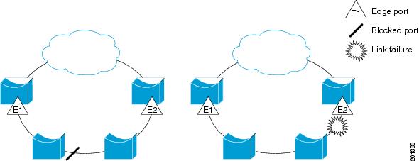
Figure 1 shows an example of a segment consisting of six ports spread across four switches. Ports E1 and E2 are configured as edge ports. When all ports are operational (as in the segment on the left), a single port is blocked, shown by the diagonal line. When there is a failure in the network, the blocked port returns to the forwarding state to minimize network disruption.
The segment shown in Figure 1 is an open segment; there is no connectivity between the two edge ports. The REP segment cannot cause a bridging loop and it is safe to connect the segment edges to any network. The traffic from a REP ring node toward the network cloud is sent to either of the edge nodes, depending on the location of the alternate port. If a failure is detected anywhere in the ring, the alternate port changes to a open port forwarding all traffic. This may cause the traffic being redirected to the other edge node depending on the fault location. It ensures that data flow is maintained between a particular REP node and the network cloud. If a failure occurs on any segment or any port on a REP segment, REP unblocks all the ports to ensure that connectivity is available through the other edge.
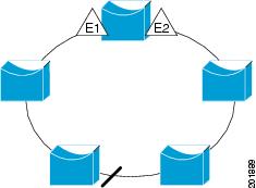
The segment shown in Figure 2, with both edge ports located on the same router, is a ring segment. In this configuration, there is connectivity between the edge ports through the segment. With this configuration, you can create a redundant connection between any two routers in the segment.
Characteristics of REP Segments
REP segments have the following characteristics:
- If all the ports in the segment are operational, one port (referred to as the alternate port) blocks traffic for each VLAN. If VLAN load balancing is configured, two ports in the segment control the blocked state of VLANs.
- If one or more ports in a segment is not operational, causing a link failure, all ports forward traffic on all VLANs to ensure connectivity. The Failed ports are blocked for all traffic, while all the other ports in the ring stay in open state.
- In case of a link failure, the alternate ports are immediately unblocked. When the failed link comes up, a logically blocked port per VLAN is selected with minimal disruption to the network. When VLAN load balancing preemption timer is set, VLAN load balancing is automatically applied after the last failure has recovered. There are 2 alternate ports when VLAN load balancing takes effect.
Understanding Link Adjacency
REP does not use an end-to-end polling mechanism between edge ports to verify link integrity. It implements local link failure detection. When enabled on an interface, the REP Link Status Layer (LSL) detects its REP-aware neighbor and establishes connectivity within the segment. All VLANs are blocked on an interface until it detects the neighbor. After the neighbor is identified, REP determines which neighbor port should become the alternate port and which ports should forward traffic.
Each port in a segment has a unique port ID. When a segment port starts, the LSL layer sends packets that include the segment ID and the port ID. The port is declared as operational after it performs a three-way handshake with a neighbor in the same segment.
A segment port does not become operational under the following conditions:
- No neighbor port has the same segment ID.
- More than one neighbor port has the same segment ID.
- The neighbor port does not acknowledge the local port as a peer.
Each port creates an adjacency with its immediate neighbor. When the neighbor adjacencies are created, the ports negotiate to determine one blocked port for the segment, the alternate port. All other ports become unblocked.
Understanding Fast Convergence
A failure in a REP segment is noticed and propagated across the ring by LSL and HFL messages. LSL messages are sent hop by hop on the control plane, with each node receiving, processing, and forwarding LSL messages. This process is time-consuming.
HFL messages are flooded in the data plane across the ring on a preconfigured administrative VLAN, using a fixed multicast address. This results in each node receiving failure notifications instantaneously. Using HFL, traffic reconvergence is achieved fast, leading to insignificant loss of traffic on segment failure.
HFL messages are handled as data packets on the nodes in a ring which do not have the REP configured. The administrative VLAN is common to all the REP segments that are configured on a node.
Convergence time varies depending on the type and number of nodes that are present on the ring.
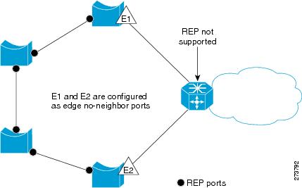
REP Edge No-Neighbor
You can configure the non-REP switch facing ports as edge no-neighbor ports. These ports inherit the properties of edge ports, and overcome the limitation of not being able to converge quickly during a failure.
You can configure the non-REP facing ports (E1 and E2) as edge no–neighbor ports as shown in Figure 1. These ports inherit all the properties of edge ports. You can configure these no-neighbor ports as any other edge port and also enable the ports to send REP topology change notifications to the aggregation switch.
Understanding REP Ports
Ports in REP segments take one of three roles or states—Failed, Open, or Alternate.
- A port configured as a regular segment port starts as a failed port.
- When the neighbor adjacencies are determined, the port transitions to the alternate port state, blocking all the VLANs on the interface. Blocked port negotiations occur and when the segment settles, one blocked port remains in the alternate role and all the other ports become open ports.
- When a failure occurs in a link, all the ports move to the failed state. When the alternate port receives the failure notification, it changes to the open state, forwarding all VLANs.
If you convert an edge port into a regular segment port, VLAN load balancing is not implemented unless it has been configured. For VLAN load balancing, you must configure two edge ports in the segment.
REP Actions on Packets
REP performs specific actions depending on the type of packets.
The following actions are taken by REP on packets that originate from an alternate port.
Packet type Block/Allow (TX) Action (TX) Block/Allow (RX) Action (RX) REP LSL packet Allow — Allow Punt to CPU REP HFL packet Allow — Allow Punt to CPU; no forward Tagged control packet Block if VLAN is blocked on the port — Block if VLAN is blocked on the port As per the configured protocol and EVC, if VLAN is not blocked. Untagged control packet Block — Block — Tagged data packet Block if VLAN is blocked on the port — Block if VLAN is blocked on the port As per EVC, if VLAN is not blocked. Untagged data packet Block — Block — REP blocks untagged packets on a port only when VLAN load balancing is not in effect. When VLAN load balancing takes effect, all the untagged packets flow across an alternate port.
The following actions are taken by REP on packets that originate from an open port (a port that is not blocked by REP).
Packet type Block/Allow (TX) Action (TX) Block/Allow (RX) Action (RX) REP LSL packet Allow — Allow Punt to CPU REP HFL packet Allow only packets that originate from the node — Allow Punt to CPU and forward as per EVC Tagged control packet Allow — Allow As per the configured protocol and EVC Untagged control packet Allow — Allow As per the configured protocol and EVC Tagged data packet Allow — Allow As per EVC Untagged data packet Allow — Allow As per EVC Default REP Configuration
REP is disabled on all the interfaces by default. When enabled, the interface is a regular segment port unless it is configured as an edge port.
When REP is enabled, the sending of segment topology change notifications (STCNs) is disabled, all VLANs are blocked, and the administrative VLAN is VLAN 1. When REP administrative VLAN or STCN configuration is changed, the changed configuration applies to ports.
When VLAN load balancing is enabled, the default is manual preemption with the delay timer disabled. If VLAN load balancing is not configured, the default action after manual preemption is to block all the VLANs at the elected alternate port.
REP Configuration Guidelines
Follow these guidelines when configuring REP:
- REP ports must be a Layer 2 IEEE 802.1Q port or 802.1AD port.
- You must configure all trunk ports in the segment with the same set of allowed VLANs, or misconfiguration occurs.
- Be careful when configuring REP through a Telnet connection. Because REP blocks all VLANs until another REP interface sends a message to unblock it or you might lose connectivity to the router if you enable REP in a Telnet session that accesses the router through the same interface.
- If REP is enabled on two ports on a router, both ports must be either regular segment ports or edge ports. REP ports follow these rules:
- If only one port on a router is configured in a segment, the port should be an edge port.
- If two ports on a router belong to the same segment, both ports must be regular segment ports.
- If two ports on a router belong to the same segment and one is configured as an edge port and one as a regular segment port (a misconfiguration), the edge port is treated as a regular segment port.
- REP interfaces come up in a blocked state and do not forward traffic till they change to open ports through exchange of LSL HELLO messages with neighbors. You need to be aware of this to avoid sudden connection losses.
- REP configuration parameters for a port must not be changed without shutting down the port. However, the VLAN range for VLAN load balancing on primary edge port can be changed without this restriction.
- When configuring VLAN load balancing, the port selected for load balancing and the primary edge port must be on different nodes. Otherwise, it may cause HFL packets to flood, when VLAN Load Balancing is activated.
- When configuring STCN, ensure that STCN propagates across the REP segments in one direction. When STCN is sent from a segment, the STCN packet must not reach the original segment. Otherwise, it may cause an infinite loop of STCN packets flowing across the segments.
- REP is not supported on service instances configured with encapsulation, untagged, or default type.
REP Configuration Sequence
You must perform the following tasks in sequence to configure REP:
- Configure the REP administrative VLAN. The range of the REP admin VLAN is from 2 to 4094. The default VLAN 1 is always configured for HFL packets. However, EVC configuration must be explicitly done for VLAN 1, or any other VLAN that is selected to be an administrative VLAN. See DLP-J29 Configure REP Administrative VLAN Using Cisco IOS Commands.
- Enable REP on ports and assign a segment ID to it. REP is disabled on all ports by default. The range of the segment ID is from 1 to 1024. See DLP-J31 Enable REP on a Port Using Cisco IOS Commands.
- Configure two edge ports in the segment; one port as the primary edge port and the other as the secondary edge port. See DLP-J31 Enable REP on a Port Using Cisco IOS Commands. If you configure two ports in a segment as the primary edge port, for example, ports on different switches, REP selects one of the ports to serve as the primary edge port based on port priority. The Primary option is enabled only on edge ports.
- Configure the primary edge port to send STCNs and VLAN load balancing to another port or to other segments. STCNs and VLAN load balancing configurations are enabled only for edge ports. See DLP-J32 Configure STCN on the Primary Edge Port Using Cisco IOS Commands and DLP-J38 Configure VLAN Load Balancing on the Primary Edge Port Using Cisco IOS Commands.
Understanding REP Administrative VLAN
To avoid the delay introduced by relaying messages related to link-failure or VLAN-blocking notification during VLAN load balancing, REP floods packets at the HFL to a regular multicast address. HFL packets are used for fast transmission of failure notification across a REP ring by flooding a BPA on a VLAN. These messages are flooded to the whole network, not just the REP segment. You can control flooding of these messages by configuring an administrative VLAN for the whole domain.
Follow these guidelines when configuring the REP administrative VLAN:
- If you do not configure an administrative VLAN, the default VLAN is VLAN 1. The default VLAN 1 is always configured.
- There can be only one administrative VLAN on a router and on a segment.
The administrative VLAN is configured at the system level. Whenever the administrative VLAN is changed, the corresponding EFP must also be manually configured to match the outer encapsulation for tagged control packets. The EFP must be associated with a bridge domain used exclusively for administrative VLAN EFPs. The VLAN marked as administrative VLAN must not be used for any other service or data traffic.
NTP-J12 Configure REP Administrative VLAN
Procedure
- DLP-J29 Configure REP Administrative VLAN Using Cisco IOS Commands
- DLP-J30 Configure REP Administrative VLAN Using CTC
Stop. You have completed this procedure.
DLP-J29 Configure REP Administrative VLAN Using Cisco IOS Commands
ProcedureDLP-J30 Configure REP Administrative VLAN Using CTC
Procedure
Step 1 Complete the NTP-J22 Log into CTC procedure at a node where you want to configure the REP administrative VLAN. Step 2 From the View menu, choose Go to Home View. Step 3 Right-click the fabric or line card and choose Open Packet Transport System View. The Packet Transport System View dialog box appears. Step 4 Click the Provisioning tab. Step 5 From the left pane, click REP. Step 6 Click the Admin VLAN Configuration tab. Step 7 From the VLAN drop–down list, choose a VLAN. The range of the REP administrative VLAN is from 2 to 4094. The default value is VLAN 1. Step 8 Click Apply. Step 9 Return to your originating procedure (NTP).
NTP-J13 Configure REP
Procedure
- DLP-J31 Enable REP on a Port Using Cisco IOS Commands
- DLP-J32 Configure STCN on the Primary Edge Port Using Cisco IOS Commands
- DLP-J33 Configure Preemption Delay on the Primary Edge Port Using Cisco IOS Commands
- DLP-J34 Create a Segment Using CTC
- DLP-J35 Edit a Segment Using CTC
Stop. You have completed this procedure.
DLP-J31 Enable REP on a Port Using Cisco IOS Commands
Procedure
Purpose This procedure enables REP on a port using Cisco IOS commands.
Tools/Equipment None Prerequisite Procedures DLP-J29 Configure REP Administrative VLAN Using Cisco IOS Commands Required/As Needed As needed Onsite/Remote Onsite or remote Security Level Provisioning or higher DLP-J32 Configure STCN on the Primary Edge Port Using Cisco IOS Commands
Procedure
Purpose This procedure configures the primary edge port to send STCNs to other segments or to an interface using Cisco IOS commands.
Tools/Equipment None Prerequisite Procedures Required/As Needed As needed Onsite/Remote Onsite or remote Security Level Provisioning or higher
Note
Perform this procedure only on edge ports and not on regular segment ports.
Command or Action Purpose
Step 1 enable
Example:Router> enableEnables privileged EXEC mode.
Step 2 configure terminal
Example:Router# configure terminalEnters global configuration mode.
Step 3 interface interface-id
Example:Router(config)# interface TenGigabitEthernet4/1Specifies the interface and enters interface configuration mode.
Step 4 rep stcn {interface interface-id | segment segment-id-list}
Example:Router(config-if)# rep stcn segment 2-5Configures the edge port to send STCNs to one or more segments or to an interface.
Step 5 end
Example:Router(config-if)# endReturns to privileged EXEC mode.
Step 6 Return to your originating procedure (NTP). —
DLP-J33 Configure Preemption Delay on the Primary Edge Port Using Cisco IOS Commands
Procedure
Command or Action Purpose
Step 1 enable
Example:Router> enableEnables privileged EXEC mode.
Step 2 configure terminal
Example:Router# configure terminalEnters global configuration mode.
Step 3 interface interface-id
Example:Router(config)# interface TenGigabitEthernet4/1Specifies the interface and enters interface configuration mode.
Step 4 rep preempt delay seconds
Example:Router(config-if)# rep preempt delay 60Configures a preempt time delay. Use this command if you want VLAN load balancing to automatically trigger after a link failure and recovery. The time delay range is from 15 to 300 seconds. The default action is manual preemption with no time delay.
Step 5 end
Example:Router(config-if)# endReturns to privileged EXEC mode.
Step 6 Return to your originating procedure (NTP). —
Example: Configure a REP Interface Using Cisco IOS Commands
The following example shows how to configure an interface as the primary edge port for segment 1, to send STCNs to segments 2 through 5, and to configure the alternate port as the port with port ID 0009001818D68700 to block all VLANs after a preemption delay of 60 seconds after a segment port failure and recovery.
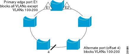
Router# configure terminal
Router(config)# interface TenGigabitEthernet4/1
Router(config-if)# rep segment 1 edge primary
Router(config-if)# rep stcn segment 2-5
Router(config-if)# rep block port 0009001818D68700 vlan all
Router(config-if)# rep preempt delay 60
Router(config-if)# end
The following example shows how to configure the VLAN blocking configuration shown in Figure 1. The alternate port is the neighbor with neighbor offset number 4. After manual preemption, VLANs 100 to 200 are blocked at this port and all other VLANs are blocked at the primary edge port E1 (TenGigabitEthernet4/1).
Router# configure terminal Router(config)# interface TenGigabitEthernet4/1 Router(config-if)# rep segment 1 edge primary Router(config-if)# rep block port 4 vlan 100-200 Router(config-if)# endDLP-J34 Create a Segment Using CTC
Procedure
Purpose This procedure creates a REP segment using CTC.
Tools/Equipment None Prerequisite Procedures DLP-J30 Configure REP Administrative VLAN Using CTC Required/As Needed As needed Onsite/Remote Onsite or remote Security Level Provisioning or higher
- You must configure two edge ports in the segment. A segment has only one primary edge port. If you configure two ports in a segment as the primary edge port, for example, ports on different switches, REP selects one of the ports to serve as the primary edge port based on port priority.
- If REP is enabled on two ports on a switch, both the ports must be either regular ports or edge ports. However, if the No-neighbor port is configured, one port can be an edge port and another port can be a regular port.
- You can also optionally configure where to send STCNs and VLAN load balancing (VLB). STCNs can be enabled on any edge port. VLB can be enabled only on primary edge ports.
NoteYou can create up to 32 REP segments.
Step 1 Complete the NTP-J22 Log into CTC procedure at a node where you want to create a segment. Step 2 From the View menu, choose Go to Home View. Step 3 Right-click the fabric or line card and choose Open Packet Transport System View. The Packet Transport System View dialog box appears. Step 4 Click the Provisioning tab. Step 5 From the left pane, click REP. Step 6 Click the Segment tab. Step 7 Click Create. The Create Segment dialog box appears. Step 8 Enter the segment ID in the Segment No field. The range of the segment ID is 1 to 1024. Step 9 From the Slot drop-down list, choose a slot. Step 10 From the Port drop-drown list, choose a REP port that must belong to this segment.
Note A REP port can belong to only one segment. Step 11 From the Port Role area, choose whether you want to configure the port as an edge port or a regular port. The options are:
Step 12 From the STCN area, configure the destination of STCN messages: Step 13 From the VLAN Load Balancing area, configure VLAN load balancing on the primary edge port:
Step 14 From the VLB Preempt Delay area, configure preemption delay on the primary edge port: Step 15 Enter the number of LSL retries before the REP link is disabled in the Retries field. The range is from 3 to 10 seconds. Step 16 Enter the LSL age out timer value in the Time field. The range is from 120 to 10000 milliseconds. Step 17 Click Next. Step 18 Enter the details of the second port to add it to the segment. Step 19 Click Finish to create a REP segment. The new segment is added to the Selected Segment table.
Step 20 Return to your originating procedure (NTP).
DLP-J35 Edit a Segment Using CTC
Procedure
Purpose This procedure edits a segment using CTC.
Tools/Equipment None Prerequisite Procedures DLP-J34 Create a Segment Using CTC Required/As Needed As needed Onsite/Remote Onsite or remote Security Level Provisioning or higher
Step 1 Complete the NTP-J22 Log into CTC procedure at a node where you want to edit a segment. Step 2 From the View menu, choose Go to Home View. Step 3 Right-click the fabric or line card and choose Open Packet Transport System View. The Packet Transport System View dialog box appears. Step 4 Click the Provisioning tab. Step 5 From the left pane, click REP. Step 6 Click the Segment tab. The list of segments appear in the Selected Segment table. Step 7 Choose a segment from the list of segments. Step 8 Click Edit. The Edit Segment dialog box appears. Step 9 Modify the values as required and click Finish. Step 10 Return to your originating procedure (NTP).
Understanding VLAN Load Balancing
REP supports VLAN load balancing, controlled by the primary edge port but occurring at any port in the segment.
You must configure two edge ports in the segment for VLAN load balancing. One edge port in the REP segment acts as the primary edge port; the other edge port as the secondary edge port.
The primary edge port always participates in VLAN load balancing in the segment. REP VLAN load balancing is achieved by blocking some VLANs at a configured alternate port and all other VLANs at the primary edge port.
NoteWhen VLAN load balancing is configured, it does not start working until triggered by either manual intervention or a link failure and recovery.
When VLAN load balancing is triggered, the primary edge port then sends out a message to alert all interfaces in the segment about the preemption. When the message is received by the secondary edge port, it is reflected into the network to notify the alternate port to block the set of VLANs specified in the message and to notify the primary edge port to block the remaining VLANs.
You can also configure a particular port in the segment to block all VLANs. VLAN load balancing is initiated only by the primary edge port and is not possible if the segment is not terminated by an edge port on each end. The primary edge port determines the local VLAN load balancing configuration.
- NTP-J14 Configure VLAN Load Balancing
- DLP-J38 Configure VLAN Load Balancing on the Primary Edge Port Using Cisco IOS Commands
- DLP-J39 Configure the Preemption for VLAN Load Balancing Using Cisco IOS Commands
- DLP-J40 Activate VLAN Load Balancing Using CTC
- DLP-J41 Deactivate VLAN Load Balancing Using CTC
NTP-J14 Configure VLAN Load Balancing
Procedure
- DLP-J38 Configure VLAN Load Balancing on the Primary Edge Port Using Cisco IOS Commands
- DLP-J39 Configure the Preemption for VLAN Load Balancing Using Cisco IOS Commands
- DLP-J40 Activate VLAN Load Balancing Using CTC
- DLP-J41 Deactivate VLAN Load Balancing Using CTC
Stop. You have completed this procedure.
DLP-J38 Configure VLAN Load Balancing on the Primary Edge Port Using Cisco IOS Commands
Procedure
Command or Action Purpose
Step 1 enable
Example:Router> enableEnables privileged EXEC mode.
Step 2 configure terminal
Example:Router# configure terminalEnters global configuration mode.
Step 3 interface interface-id
Example:Router(config)# interface TenGigabitEthernet4/1Specifies the interface and enters the interface configuration mode.
Step 4 rep block port {id port-id | neighbor-offset | preferred} vlan {vlan-list | all}
Example:Router(config-if)# rep block port 0009001818D68700 vlan allConfigures VLAN load balancing on the primary edge port, identifies the REP alternate port, and configures the VLANs to be blocked on the alternate port.
- Enter the id port-id to identify the alternate port by port ID. The port ID is automatically generated for each port in the segment. You can view interface port IDs by entering the show interface interface-id rep detail command in privileged EXEC mode.
- Enter a neighbor-offset number to identify the alternate port as a downstream neighbor from an edge port. The range is from –256 to 256, with negative numbers indicating the downstream neighbor from the secondary edge port. A value of 0 is invalid. Enter -1 to identify the secondary edge port as the alternate port.
- Enter preferred to select the regular segment port previously identified as the preferred alternate port for VLAN load balancing.
- Enter vlan vlan-list to block one VLAN or a range of VLANs.
- Enter vlan all to block all the VLANs.
Step 5 end
Example:Router(config-if)# endReturns to privileged EXEC mode.
Step 6 Return to your originating procedure (NTP). —
DLP-J39 Configure the Preemption for VLAN Load Balancing Using Cisco IOS Commands
Procedure
Purpose This procedure configures the preemption for VLAN load balancing using Cisco IOS commands. Tools/Equipment None Prerequisite Procedures DLP-J38 Configure VLAN Load Balancing on the Primary Edge Port Using Cisco IOS Commands Required/As Needed As needed Onsite/Remote Onsite or remote Security Level Provisioning or higher Ensure that all the other segment configuration has been completed before setting preemption for VLAN load balancing. When you enter the rep preempt segment segment-id command, a confirmation message appears before the command is executed because preemption for VLAN load balancing can disrupt the network.
If you do not enter the rep preempt delay seconds interface configuration command on the primary edge port to configure a preemption time delay, the default configuration is to manually trigger VLAN load balancing on the segment. Use the show rep topology privileged EXEC command to see which port in the segment is the primary edge port.
Perform these steps on the router that has the segment with the primary edge port.
Command or Action Purpose
Step 1 enable
Example:Router> enableEnables privileged EXEC mode. Enter your password if prompted.
Step 2 rep preempt segment segment-id
Example:Router# rep preempt segment 1Manually triggers VLAN load balancing on the segment.
Note Confirm the action before the command is executed.
Step 3 show rep topology
Example:Router# show rep topologyDisplays the REP topology information.
Step 4 Return to your originating procedure (NTP). —
DLP-J40 Activate VLAN Load Balancing Using CTC
Procedure
Purpose This procedure activates VLAN load balancing using CTC.
Tools/Equipment None Prerequisite Procedures DLP-J34 Create a Segment Using CTC Required/As Needed As needed Onsite/Remote Onsite or remote Security Level Provisioning or higher
NoteWhen VLAN load balancing is activated, the default configuration is manual preemption with the delay timer disabled.
Step 1 Complete the NTP-J22 Log into CTC procedure at a node where you want to activate VLAN load balancing. Step 2 From the View menu, choose Go to Home View. Step 3 Right-click the fabric or line card and choose Open Packet Transport System View. The Packet Transport System View dialog box appears. Step 4 Click the Provisioning tab. Step 5 From the left pane, click REP. Step 6 Click the Segment tab. The list of segments appear. Step 7 Choose a segment from the list of segments. Step 8 Click Activate VLB to activate VLAN load balancing. Step 9 Return to your originating procedure (NTP).
DLP-J41 Deactivate VLAN Load Balancing Using CTC
Procedure
Purpose This procedure deactivates VLAN load balancing using CTC.
Tools/Equipment None Prerequisite Procedures DLP-J34 Create a Segment Using CTC Required/As Needed As needed Onsite/Remote Onsite or remote Security Level Provisioning or higher
Step 1 Complete the NTP-J22 Log into CTC procedure at a node where you want to deactivate VLAN load balancing. Step 2 From the View menu, choose Go to Home View. Step 3 Right-click the fabric or line card and choose Open Packet Transport System View. The Packet Transport System View dialog box appears. Step 4 Click the Provisioning tab. Step 5 From the left pane, click REP. Step 6 Click the Segment tab. The list of segments appear. Step 7 Choose a segment from the list of segments. Step 8 Click Deactivate VLB to deactivate VLAN load balancing. Step 9 Return to your originating procedure (NTP).
Understanding REP Configurable Timers
The REP Configurable Timer (REP Fast Hellos) feature provides a fast reconvergence in a ring topology with higher timer granularity and quicker failure detection on the remote side. This feature also supports improved convergence of REP segments having nodes with copper based SFPs, where the link detection time varies between 300 ms to 700 ms.
With the REP Link Status Layer (LSL) ageout timer configuration, the failure detection time can be configured between a range of 120 to 10000 ms, in multiples of 40 ms. The result of this configuration is that, even if the copper pull takes about 700 ms to notify the remote end about the failure, the REP configurable timers process will detect it much earlier and take subsequent action for the failure recovery within 200 ms.
The LSL retries and LSL ageout timer is related in terms of LSL hello packet transmission. The LSL hello packet interval is measured by lsl_age_timer/lsl_retries value. The LSL hello packet interval value must be at least 40 ms.
Restrictions and Usage Guidelines
Follow these guidelines and restrictions:
- While configuring REP configurable timers, we recommend that you shut the port, configure REP and only then use the no shut command. This prevents the REP from flapping and generating large number of internal messages.
- If incompatible switches are neighbors, configure the correct LSL Age Out value first. In some scenarios, you might not get the expected convergence range.
- While configuring REP configurable timers, we recommend that you configure the REP LSL number of retries first and then configure the REP LSL ageout timer value.
- NTP-J15 Configure REP Timers
- DLP-J42 Configure REP Link Status Layer Retries Using Cisco IOS Commands
- DLP-J43 Configure the REP Link Status Layer Ageout Timer Using Cisco IOS Commands
NTP-J15 Configure REP Timers
Procedure
- DLP-J42 Configure REP Link Status Layer Retries Using Cisco IOS Commands
- DLP-J43 Configure the REP Link Status Layer Ageout Timer Using Cisco IOS Commands
Stop. You have completed this procedure.
DLP-J42 Configure REP Link Status Layer Retries Using Cisco IOS Commands
Procedure
Command or Action Purpose
Step 1 enable
Example:Router> enableEnables privileged EXEC mode.
Step 2 configure terminal
Example:Router# configure terminalEnters global configuration mode.
Step 3 interface type number
Example:Router(config)# interface TenGigabitEthernet4/1Specifies the interface to configure and enters interface configuration mode.
Step 4 rep lsl-retries no-of-retries
Example:Router(config-if)# rep lsl-retries 4Configures the number of retries before the REP link is disabled. The range of retries is from 3 to 10. The default number of LSL retries is 5.
Step 5 end
Example:Router(config-if)# endReturns to privileged EXEC mode.
Step 6 Return to your originating procedure (NTP). —
Example: Configure REP Link Status Layer Retries
The following example shows how to configure REP LSL retries using Cisco IOS commands.
Router# enable
Router# configure terminal
Router(config)# interface TenGigabitEthernet4/1
Router(config-if)# rep segment 2 edge primary
Router(config-if)# rep lsl-retries 4
Router(config-if)# end
DLP-J43 Configure the REP Link Status Layer Ageout Timer Using Cisco IOS Commands
Procedure
Command or Action Purpose
Step 1 enable
Example:Router> enableEnables privileged EXEC mode.
Step 2 configure terminal
Example:Router# configure terminalEnters global configuration mode.
Step 3 interface type number
Example:Router(config)# interface TenGigabitEthernet4/1Specifies the interface to configure and enters interface configuration mode.
Step 4 rep lsl-age-timer lsl-age-timer
Example:Router(config-if)# rep lsl-age-timer 2000Configures REP link status layer ageout timer value. The range of lsl-age-timer is between 120 ms and 10000 ms, in multiples of 40 ms. The default LSL ageout timer value is 5 seconds. The recommended LSL ageout timer value is 2 seconds.
Step 5 end
Example:Router(config-if)# endReturns to privileged EXEC mode.
Step 6 Return to your originating procedure (NTP). —
Example: Configure the REP LSL Ageout Timer
The following example shows how to configure REP LSL ageout timer value using Cisco IOS commands.
Router# enable
Router# configure terminal
Router(config)# interface TenGigabitEthernet4/1
Router(config-if)# rep segment 1 edge primary
Router(config-if)# rep lsl-age-timer 2000
Router(config-if)# end
Understanding REP with EVC
REP can be integrated with an Ethernet Virtual Circuit (EVC) port using the REP over EVC feature. This feature allows you to configure and manage ports at the service instance level. An EVC port can have multiple service instances. Each service instance corresponds to a unique Ethernet Flow Point (EFP).
This feature allows you to configure an EVC port to participate in a REP segment. REP can selectively block or forward data traffic on particular VLANs. For EVC, the VLAN ID refers to the outer tag of the encapsulation that is configured on a service instance.
NoteREP is supported on an EVC cross-connect and bridge domain service. REP is not supported for Ethernet Private Line and Ethernet Virtual Private Line services.
REP does not support protection or loop prevention on ring interfaces which have one of the following EFP configurations:
Though a REP ring will converge with such interfaces, traffic loop can happen depending on the EVC configuration.
Using the REP over EVC feature, you can:
Restrictions and Usage Guidelines
When configuring REP over EVC, follow these guidelines and restrictions:
- It is recommended that you begin by configuring one port and then configure the contiguous ports to minimize the number of segments and the number of blocked ports.
- REP is not supported on LACP.
- If more than two ports in a segment fail when no external neighbors are configured, one port goes into a forwarding state to maintain connectivity during configuration.
- To avoid misconfiguration, you must configure all the trunk ports in the segment with the same set of allowed VLANs.
- Because REP blocks all VLANs until another REP interface sends a message to unblock it, you might lose connectivity to the port. This happens if you enable REP in a telnet session that accesses the EVC port through the same interface.
- On a router if REP is enabled on two ports for a segment, both ports must either be a regular segment ports or edge ports. REP ports follow these rules on a router:
- If only one port is configured in a segment, the port should be an edge port.
- If two ports belong to the same segment, both ports must be edge ports or the regular segment ports.
- If two ports belong to the same segment and one is configured as an edge port and other as a regular segment port, the edge port is treated as a regular segment port.
- There can be only two edge ports in a segment; if there are two edge routers in a segment, each router can have only one edge port. All the other ports on the edge router function as normal ports.
- REP interfaces come up in a blocked state and remains in a blocked state until notified that it is safe to unblock.
- REP relays all LSL Protocol Data Units (PDUs) in untagged frames and only HFL packets are relayed on the administrative VLAN.
- REP is not supported on EtherChannels. It is supported on EVC port-channels. REP is implemented on port-channels instead of its individual member links.
- REP is not supported on static port-channels.
- In case of double VLAN tagged frame, REP is implemented only on the outer VLAN tag.
- When an edge no-neighbor is configured on a router, configuring and unconfiguring an edge port is not allowed.
- NTP-J16 Configure REP over EVC
- DLP-J44 Configure REP over EVC Using a Cross–Connect Using Cisco IOS Commands
- DLP-J45 Configure REP over EVC Using the Bridge Domain Using Cisco IOS Commands
- Verify REP with EVC Configuration Using Cisco IOS Commands
NTP-J16 Configure REP over EVC
Procedure
- DLP-J44 Configure REP over EVC Using a Cross–Connect Using Cisco IOS Commands
- DLP-J45 Configure REP over EVC Using the Bridge Domain Using Cisco IOS Commands
Stop. You have completed this procedure.
DLP-J44 Configure REP over EVC Using a Cross–Connect Using Cisco IOS Commands
Procedure
Command or Action Purpose
Step 1 enable
Example:Router> enableEnables privileged EXEC mode.
Step 2 configure terminal
Example:Router# configure terminalEnters global configuration mode.
Step 3 interface type number
Example:Router(config)# interface TenGigabitEthernet4/1Specifies the interface to configure and enters the interface configuration mode.
Step 4 ether vlan color-block all
Example:Router(config-if)# ether vlan color-block allConfigures REP to block cross-connect type of service instances.
Step 5 service instance id ethernet [evc-id]
Example:Router(config-if)# service instance 101 ethernetConfigures an Ethernet service instance on an interface and enters the service instance configuration mode.
Step 6 encapsulation dot1q {any | vlan-id [vlan-id [-vlan-id]]} second-dot1q {any | vlan-id [vlan-id [-vlan-id]]}
Example:Router(config-if-srv)# encapsulation dot1q 100 second-dot1q 200Configures the encapsulation. Defines the matching criteria to be used to map ingress dot1q frames on an interface to the appropriate service instance.
Step 7 rewrite ingress tag {push {dot1q vlan-id | dot1q vlan-id second-dot1q vlan-id | dot1ad vlan-id dot1q vlan-id} | pop {1 | 2} | translate {1-to-1 {dot1q vlan-id | dot1ad vlan-id}| 2-to-1 dot1q vlan-id | dot1ad vlan-id}| 1-to-2 {dot1q vlan-id second-dot1q vlan-id | dot1ad vlan-id dot1q vlan-id} | 2-to-2 {dot1q vlan-id second-dot1q vlan-id | dot1ad vlan-id dot1q vlan-id}} {symmetric}
Example:Router(config-if-srv)# rewrite ingress tag dot1q single symmetricSpecifies the rewrite operation to be applied on the frame ingress to the service instance.
Step 8 xconnect loopback_id vc_id encapsulation mpls
Example:Router(config-if-srv)# xconnect 10.0.0.2 999 encapsulation mplsConfigures the forwarding mechanism on a service instance. Ensure that the MPLS connectivity is up.
Step 9 rep segment segment-id [edge [no-neighbor] [primary]] [preferred]
Example:Router(config-if)# rep segment 3 edgeConfigures REP over EVC. The segment ID range is from 1 to 1024.
Note You must configure a primary and secondary edge port on each segment. The following optional keywords are available.
- Enter edge to configure the port as an edge port. Entering edge without the primary keyword configures the port as the secondary edge port. Each segment has only two edge ports.
- Enter no-neighbor to specify that the edge port must not have a neighbor port.
- Enter primary to configure the port as the primary edge port where you can configure VLAN load balancing.
- Enter preferred to indicate that the port is the preferred alternate port or the preferred port for VLAN load balancing.
Note Configuring a port as preferred does not guarantee that it becomes the alternate port; it merely gives it a slight edge among equal contenders. The alternate port is usually a previously failed port.
Step 10 exit
Example:Router(config-if)# exitExits interface configuration mode.
Step 11 Return to your originating procedure (NTP). —
Example: Configure REP over EVC Using Cross–Connect
The following example shows how to configure REP over EVC using cross–connect.
Router# enable
Router# configure terminal
Router(config)# interface TenGigabitEthernet4/1
Router(config-if)# service instance 10 ethernet
Router(config-srv)# encapsulation dot1q 20
Router(config-if-srv)# rewrite ingress tag push dot1q 20 symmetric
Router(config-if-srv)# xconnect 10.0.0.2 999 encapsulation MPLS
Router(config-if-srv)# exit
Router(config-if)# rep segment 2 edge
Router(config-if)# end
DLP-J45 Configure REP over EVC Using the Bridge Domain Using Cisco IOS Commands
Procedure
Command or Action Purpose
Step 1 enable
Example:Router> enableEnables privileged EXEC mode.
Step 2 configure terminal
Example:Router# configure terminalEnters global configuration mode.
Step 3 interface type number
Example:Router(config)# interface TenGigabitEthernet4/1Specifies the interface to configure and enters interface configuration mode.
Step 4 service instance id ethernet [evc-id]
Example:Router(config-if)# service instance 101 ethernetConfigures an Ethernet service instance on an interface and enters service instance configuration mode.
Step 5 encapsulation dot1q {any | vlan-id [vlan-id [-vlan-id]]} second-dot1q {any | vlan-id [vlan-id [-vlan-id]]}
Example:Router(config-if-srv)# encapsulation dot1q 100 second dot1q 200Configures the encapsulation. Defines the matching criteria to be used in order to map ingress dot1q frames on an interface to the appropriate service instance.
Step 6 rewrite ingress tag {push {dot1q vlan-id | dot1q vlan-id second-dot1q vlan-id | dot1ad vlan-id dot1q vlan-id} | pop {1 | 2} | translate {1-to-1 {dot1q vlan-id | dot1ad vlan-id}| 2-to-1 dot1q vlan-id | dot1ad vlan-id}| 1-to-2 {dot1q vlan-id second-dot1q vlan-id | dot1ad vlan-id dot1q vlan-id} | 2-to-2 {dot1q vlan-id second-dot1q vlan-id | dot1ad vlan-id dot1q vlan-id}} {symmetric}
Example:Router(config-if-srv)# rewrite ingress tag push dot1q 20Specifies the rewrite operation to be applied on the frame ingress to the service instance.
Step 7 bridge-domain bridge-id [split-horizon]
Example:Router(config-if-srv)# bridge-domain 10Configures the bridge domain to add another VLAN tag of type bridge-domain to the incoming packet.
Step 8 exit
Example:Router(config-if-srv)# exitExits service instance configuration mode.
Step 9 rep segment segment-id [edge [no-neighbor] [primary]] [preferred]
Example:Router(config-if)# rep segment 2 edge primaryConfigures REP over EVC. The segment ID range is from 1 to 1024.
Note You must configure a primary and secondary edge port on each segment. The following optional keywords are available.
- Enter edge to configure the port as an edge port. Entering edge without the primary keyword configures the port as the secondary edge port. Each segment has only two edge ports.
- Enter no-neighbor to specify that the edge port must not have a neighbor port.
- Enter primary to configure the port as the primary edge port where you can configure VLAN load balancing.
- Enter preferred to indicate that the port is the preferred alternate port or the preferred port for VLAN load balancing.
Note Configuring a port as preferred does not guarantee that it becomes the alternate port; it merely gives it a slight edge among equal contenders. The alternate port is usually a previously failed port.
Step 10 exit
Example:Router(config-if)# exitExits interface configuration mode.
Step 11 Return to your originating procedure (NTP). —
Example: Configure REP over EVC Using the Bridge Domain
The following example shows how to configure REP over EVC using the bridge domain.
Router# enable
Router# configure terminal
Router(config)# interface TenGigabitEthernet4/1
Router(config-if)# service instance 10 ethernet
Router(config-if-srv)# encapsulation dot1q 10
Router(config-if-srv)# rewrite ingress tag push dot1q 10 symmetric
Router(config-if-srv)# bridge-domain 100
Router(config-if-srv)# exit
Router(config-if)# rep segment 2 edge
Router(config-if)# end
Verify REP with EVC Configuration Using Cisco IOS Commands
You can use the show rep topology, show rep topology detail and show interface rep commands to verify REP over EVC configuration.
Example of the show rep topology Command
Router# show rep topologyREP Segment 1 BridgeName PortName Edge Role ---------------- ---------- ---- ---- 10.64.106.63 Te5/4 Pri Open 10.64.106.228 Te3/4 Open 10.64.106.228 Te3/3 Open 10.64.106.67 Te4/3 Open 10.64.106.67 Te4/4 Alt 10.64.106.63 Te4/4 Sec Open REP Segment 3 BridgeName PortName Edge Role ---------------- ---------- ---- ---- 10.64.106.63 Gi50/1 Pri Open SVT_3400_2 Gi0/3 Open SVT_3400_2 Gi0/4 Open 10.64.106.68 Gi40/2 Open 10.64.106.68 Gi40/1 Open 10.64.106.63 Gi50/2 Sec AltExample of the show rep topology detail Command
Router# show rep topology detailREP Segment 1 10.64.106.63, Te5/4 (Primary Edge) Open Port, all vlans forwarding Bridge MAC: 0005.9b2e.1700 Port Number: 010 Port Priority: 000 Neighbor Number: 1 / [-6] 10.64.106.228, Te3/4 (Intermediate) Open Port, all vlans forwarding Bridge MAC: 0005.9b1b.1f20 Port Number: 010 Port Priority: 000 Neighbor Number: 2 / [-5] 10.64.106.228, Te3/3 (Intermediate) Open Port, all vlans forwarding Bridge MAC: 0005.9b1b.1f20 Port Number: 00E Port Priority: 000 Neighbor Number: 3 / [-4] 10.64.106.67, Te4/3 (Intermediate) Open Port, all vlans forwarding Bridge MAC: 0005.9b2e.1800 Port Number: 008 Port Priority: 000 Neighbor Number: 4 / [-3] 10.64.106.67, Te4/4 (Intermediate) Alternate Port, some vlans blocked Bridge MAC: 0005.9b2e.1800 Port Number: 00A Port Priority: 000 Neighbor Number: 5 / [-2] 10.64.106.63, Te4/4 (Secondary Edge) Open Port, all vlans forwarding Bridge MAC: 0005.9b2e.1700 Port Number: 00A Port Priority: 000 Neighbor Number: 6 / [-1]Example of the show interface rep detail Command
Router# show interface TenGigabitEthernet4/1 rep detailTenGigabitEthernet4/1 REP enabled Segment-id: 3 (Primary Edge) PortID: 03010015FA66FF80 Preferred flag: No Operational Link Status: TWO_WAY Current Key: 02040015FA66FF804050 Port Role: Open Blocked VLAN: <empty> Admin-vlan: 1 Preempt Delay Timer: disabled Configured Load-balancing Block Port: none Configured Load-balancing Block VLAN: none STCN Propagate to: none LSL PDU rx: 999, tx: 652 HFL PDU rx: 0, tx: 0 BPA TLV rx: 500, tx: 4 BPA (STCN, LSL) TLV rx: 0, tx: 0 BPA (STCN, HFL) TLV rx: 0, tx: 0 EPA-ELECTION TLV rx: 6, tx: 5 EPA-COMMAND TLV rx: 0, tx: 0 EPA-INFO TLV rx: 135, tx: 136REP with Other Features
REP supports up to 32 segments in each node. REP supports up to 5 segments or 10 ports on a single card or CPT 50 panel.
REP with High Availability
When the active fabric card fails, REP supports hot switchover to the standby fabric card. There might be momentary loss of traffic when the standby fabric card takes over as the active fabric card.
REP with Multicast
In a REP ring, the multicast traffic may not flow across all the elements on the ring; the traffic depends on the path taken from the multicast router to the client. The elements that do not form the multicast path do not become members of the multicast group.
When there is a failure in a REP ring, it is possible that the new path between the multicast router and the client may traverse elements which were previously not part of the multicast traffic path. These elements do not forward multicast traffic till they see a query from multicast router and a join from the client. A multicast router may only send query after long intervals, which results in a large traffic hit. All the ports that are enabled with REP must be configured as static mrouter ports to solve this issue.