-
Cisco Prime Network Administration Guide, 3.10
-
Preface
-
Set Up Prime Network and Its Components
-
Manage the Prime Network Software Image and Backups
-
Manage the Prime Network Components: Gateway, Units, AVMs, and VNEs
-
Manage Network Elements (VNEs)
-
Manage Redundancy for Units and Processes
-
Control Device Access Using Device Scopes
-
Manage User Accounts
-
Manage the Database and System Data
-
Control Event Monitoring
-
Manage Workflows and Activations
-
System Security
-
Perform Advanced VNE Configurations
-
Device Configuration Tasks for Proper Modeling
-
Prime Network Log Files
-
Manage the Prime Network Registry
-
VNE Properties Reference
-
Index
-
 Feedback
Table Of Contents
Configure VNEs and Troubleshoot VNE Problems
What is the Difference Between a VNE and a Device?
Check Device Discovery, VNE Status, and VNE States
How VNEs are Modeled and Monitored
Check VNE General Status (Up, Down, Disconnected, Unreachable)
Check VNE Communication State (Connectivity)
Check VNE Investigation States (Modeling)
Stop, Start, and Move VNEs to Maintenance Mode
Steps and Required Information for Adding VNEs
Create Custom VNE Schemes and VNE Defaults for SNMP and Telnet/SSH
Configure Default SNMP and Telnet/SSH Settings
Methods for Adding Devices (Creating VNEs)
Add Devices Using Network Discovery
Add New Device Support by Installing Device Packages
Find Out if New Device Support is Available
Identify Which DPs Are Installed on the Gateway
Identify Which Driver a VNE Is Using
Change the Device Package a VNE Is Using
Download and Install New Driver Files
Change a VNE IP Address and Other VNE Properties
Troubleshoot Device Connectivity Issues (VNE Communication States)
What Determines the VNE Communication State (Device Reachability)?
Steps to Troubleshoot VNE Communication State Issues
Troubleshoot Device Modeling Issues (VNE Investigation States)
Configure VNEs and Troubleshoot VNE Problems
VNEs are the building blocks of Prime Network model. These topics focus on VNEs—how devices are discovered by VNEs, how to check and troubleshoot VNE problems, and how to make changes to VNEs. Add Devices to Prime Network, explains the various methods you can use to create VNEs and thus add devices to the model, including how to decide which method is best for your configuration.
•
What is the Difference Between a VNE and a Device?
•
•
•
•
See these topics for step-by-step procedures for troubleshooting modeling and connectivity problems:
•
•
What is the Difference Between a VNE and a Device?
Actions you perform on VNEs are different from actions you perform on devices. It is important to understand the difference between VNEs and devices. VNEs are autonomous, miniature engines, and each VNE is in charge of a single device. The VNE maintains a real-time virtual model of the device (both physical and logical), and its connectivity references to its immediate neighbors. The VNE is an entity that only exists within Prime Network; the real device is a separate entity. For example:
•
•
Operators are shielded from much of the backend workings of the VNE because their concern is the real NE being managed. But the VNE process must be completely functional in order for Prime Network to properly model and monitor the device. This administrative condition of the VNE is expressed through the VNE status.
Check Device Discovery, VNE Status, and VNE States
The Prime Network GUI clients provide some common information so that you do not have to switch between clients. For example, just as you can get a subset of VNE information from the Vision GUI client, you can also get a subset of device information from the Administration GUI client. The following table shows what type of information is displayed in the Administration GUI client when you right-click a VNE and choose either Properties or Inventory.
These topics explain how Prime Network discovers devices and how to check on the status of modeling and connectivity.
•
•
•
•
How VNEs are Modeled and Monitored
When you add a device to Prime Network, Prime Network creates an autonomous VNE that models that single device. The VNE then uses the NE's IP address and southbound management interfaces (such as SNMP or Telnet) to identify the NE by vendor, device family, device subfamily, device type and software version. When the NE type is determined, the VNE collects the basic inventory, both physical and logical, determines its status, and attempts to determine its place in the network topology. The VNE negotiates with peer VNEs (which represent peer NEs) to determine the connectivity and topology at different layers. This model of the network topology, device state, and device inventory is constantly being updated by the VNE, which tracks every change that occurs in the NE or in the network.
VNE Schemes
The information that the VNE collects is determined by the VNE scheme. You choose a scheme when you create a VNE. VNE schemes determine what data should be retrieved for each device, and which commands and protocols Prime Network should use to collect that data. When you create a VNE, Prime Network provides a drop-down of available schemes:
For example, devices poll with SNMP, but might also use CLI to poll additional information. Because the IpCore scheme assumes that the device is used as part of an MPLS VPN network containing P and PE devices, Prime Network therefore models these VNEs in a slightly different way. In most cases you can use the Product scheme with customer edge (CE) devices. You can designate a VNE as a core router by setting it to work with the IpCore scheme, or as an edge router by setting it to work with the Product scheme.
If you only want to model a certain set of technologies, create a custom scheme. The scheme is added to the gateway, and you can apply it to VNEs using the Administration client. See Create a Custom VNE Scheme.
For guidance on choosing a scheme, see Choosing a VNE Scheme (Check Technologies and Device Types).
How VNEs Are Monitored and Updated
A VNE's administrative condition is conveyed by its VNE status—for example, if you stop a VNE, its VNE status will be Down. VNE states, on the other hand, describe the degree to which the VNE has discovered and modeled a device, and the disposition of the communication between the VNE and the device it models. VNE state information is intentionally granular so that you can use it to troubleshoot problems.
All VNEs have two states:
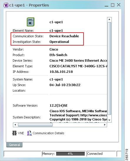
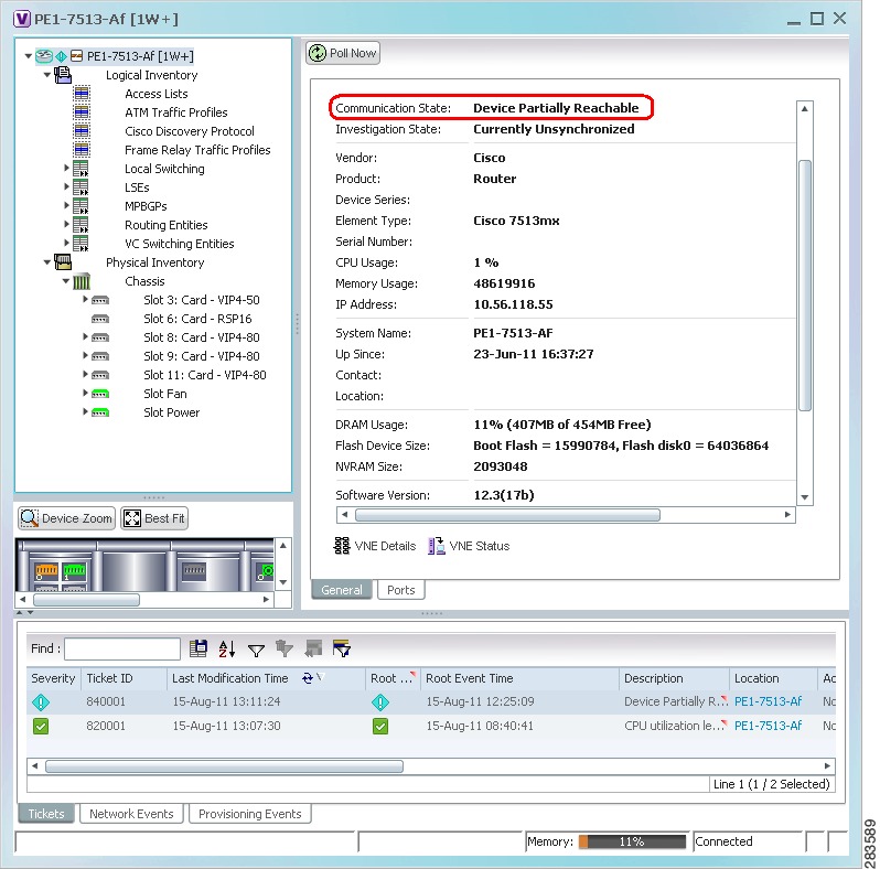
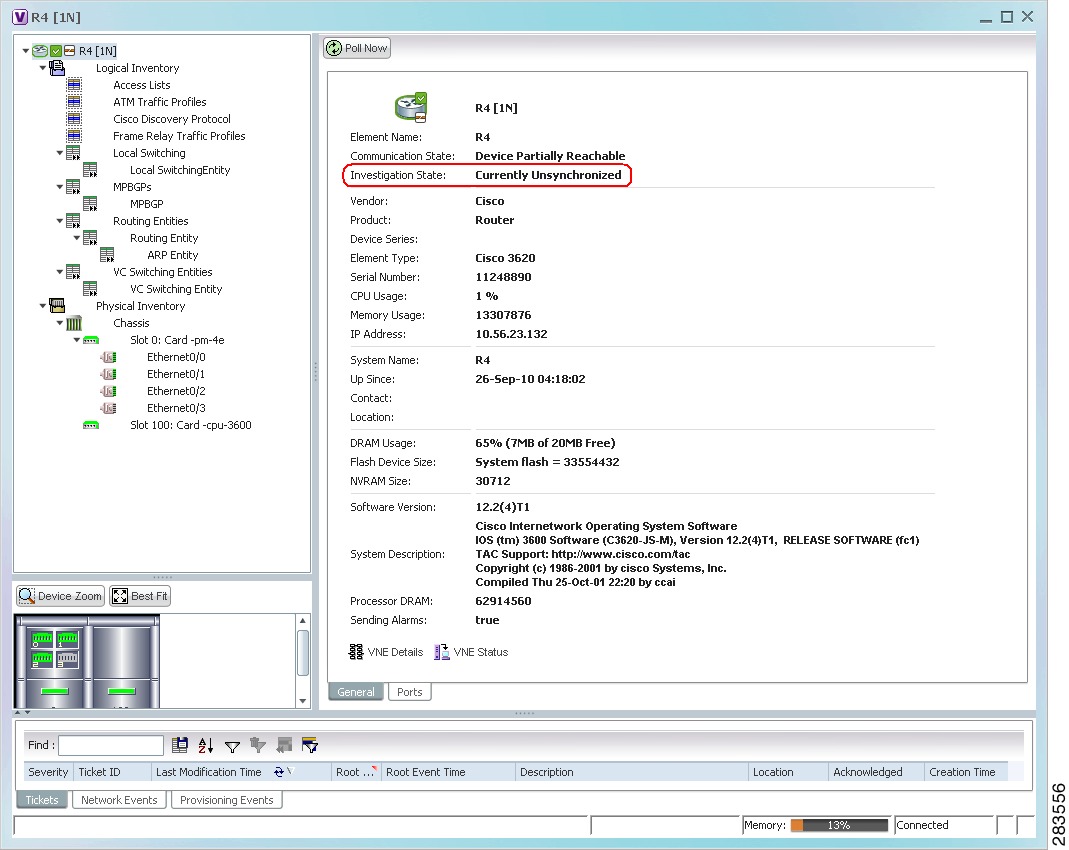
Both the communication and investigation states are displayed in Prime Network Vision when you open a device properties window, as shown in Figure 4-1.
Figure 4-1 VNE Communication and Investigation States (in Prime Network Vision)
Note
If you want more information about the communication state, click Communication Details to get information on the status of:
•
•
This information is helpful for troubleshooting device reachability problems. For more information, see Check VNE Communication State (Connectivity).
Check VNE General Status (Up, Down, Disconnected, Unreachable)
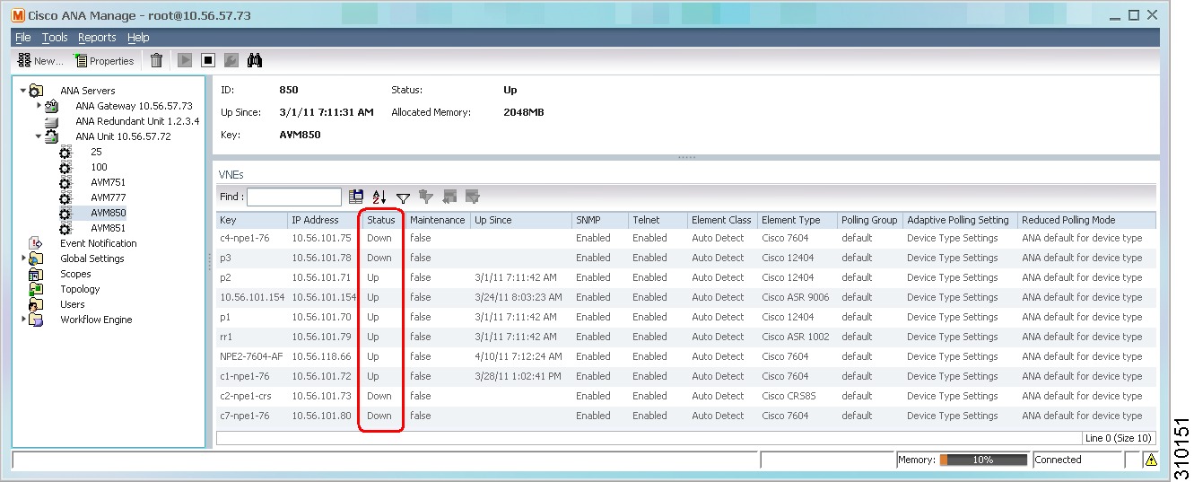
Like AVM status, VNE status indicates the administrative condition of the VNE: Starting Up, Up, Shutting Down, Down. If the gateway server cannot communicate with the VNE, the VNE status will be Unreachable. (Remember that this is the status of the VNE, not the status of the physical device.) This information is displayed in the Administration GUI client when you select an AVM (see Figure 4-2).
Figure 4-2 VNE Status in AVM Window
Starting and stopping VNEs is entirely user-directed, as explained in Stop, Start, and Move VNEs to Maintenance Mode. Table 4-1 lists the possible VNE status values that you may see in a table of VNEs.
Check VNE Communication State (Connectivity)
VNE communication states convey the status of connectivity between:
•
•
When connectivity problems occur, it is normally in the management area—that is, between a VNE and a device. Devices and VNEs communicate using SNMP, Telnet, ICMP, traps, syslogs, and others—all of which determine whether a device is truly reachable. If a problem occurs, Prime Network runs tests tailored to each (enabled) protocol to determine the seriousness of the problem. Prime Network does not change the communication state to Device Unreachable unless all of the enabled device management protocols are unresponsive, and the device is not generating syslogs or traps.
Table 4-2 describes all of the possible VNE communication states. It also shows the GUI decorator for each state, where applicable. For information on troubleshooting communication state issues, see Steps to Troubleshoot VNE Communication State Issues.
The
icon indicates a network element has been deleted (or moved). The state will show N/A for Cloud VNEs because Cloud VNEs do not represent a real network element (see Create Connections for Unmanaged Network Segments (Cloud VNEs and Links)).
Table 4-2 VNE Communication States
Agent Not Loaded
The VNE is not responding to the gateway because it was stopped, or it was just created. This communication state is the equivalent of the Defined Not Started investigation state.
None
VNE/Agent Unreachable
The VNE is not responding to the gateway. This can happen if the unit or AVM is overutilized, the connection between the gateway and unit or AVM was lost, or the VNE is not responding in a timely fashion. (A VNE in this state does not mean the device is down; it might still be processing network traffic.)
Connecting
The VNE is starting and the initial connection has not yet been made to the device. This is a momentary state. Because the investigation state decorator (the hourglass) will already be displayed, a special GUI decorator is not required.
None
Device Partially Reachable
The element is not fully reachable because at least one protocol is not operational.
Note
Device Reachable
All element protocols are enabled and connected.
Note
None
Device Unreachable
The connection between the VNE and the device id down because all of the protocols are down (though the device might be sending traps or syslogs).
Note
Tracking Disabled
The reachability detection process is not enabled for any of the protocols used by the VNE (specifically, the trackreachability registry key is not set to true; see Change How Protocols are Tested for Reachability). The VNE will not perform reachability tests nor will Cisco Prime Network generate reachability-related events. In some cases this is desirable; for example, tracking for Cloud VNEs should be disabled because Cloud VNEs represent unmanaged network segments.
Because this is a user-defined mode (rather than an error or transitional mode), Cisco Prime Network does not display a decorator for this state. To troubleshoot a VNE that is in this state, check the VNE Status Details window; see Troubleshoot Device Connectivity Issues (VNE Communication States).
None
Check VNE Investigation States (Modeling)
VNE investigation states describe how successfully a VNE has modeled the device it represents. These states describe all of the possibilities in the VNE life cycle, from when the VNE is added to Prime Network, through the device modelling, until the VNE is stopped. Table 4-3 describes all of the possible VNE investigation states. It also shows the GUI decorator for each state, where applicable.
Note
For troubleshooting information, see Troubleshoot Device Modeling Issues (VNE Investigation States).
The
icon indicates a network element has been deleted (or moved). The state will show N/A for Cloud VNEs because Cloud VNEs do not represent a real network element (see Create Connections for Unmanaged Network Segments (Cloud VNEs and Links)).
Table 4-3 VNE Investigation States
Defined Not Started
A new VNE was created (and is starting); or an existing VNE was stopped. In this state, the VNE is managed and is validating support for the device type. (This investigation state is the equivalent of the Agent Not Loaded communication state.) A VNE remains in this state until it is started (or restarted).
None
Unsupported
The device type is either not supported by Prime Network or is misconfigured (it is using the wrong scheme, or is using reduced polling but the device does not support it).
To extend Cisco Prime Network functionality so that it recognizes unsupported devices, use the VNE Customization Builder. See the Cisco Prime Network 3.10 Customization Guide.
Discovering
The VNE is building the model of the device (the device type was found and is supported by Cisco Prime Network). A VNE remains in this state until all device commands are successfully executed at least once, or until there is a discovery timeout.
Operational
The VNE has a stable model of the device. Modeling may not be fully complete, but there is enough information to monitor the device and make its data available to other applications, such as activation scripts. A VNE remains in this state unless it is stopped or moved to the maintenance state, or there are device errors.
None
Currently Unsynchronized
The VNE model is inconsistent with the device. This can be due to a variety of reasons; for a list of these reasons along with troubleshooting tips, see Troubleshoot Device Connectivity Issues (VNE Communication States).
Maintenance
VNE polling was suspended because it was manually moved to this state (by right-clicking the VNE and choosing Actions > Maintenance). The VNE remains in this state until it is manually restarted. A VNE in the maintenance state has the following characteristics:
•
•
•
•
The VNE is moved to the Stopped state if: it is VNE is moved, the parent AVM is moved or restarted, the parent unit switches to a standby unit, or the gateway is restarted.
Partially Discovered
The VNE model is inconsistent with the device because a required device command failed, even after repeated retries. A common cause of this state is that the device contains an unsupported module. To extend Cisco Prime Network functionality so that it recognizes unsupported modules, use the VNE Customization Builder. See the Cisco Prime Network 3.10 Customization Guide.
Shutting Down
The VNE has been stopped or deleted by the user, and the VNE is terminating its connection to the device.
Stopped
The VNE process has terminated; it will immediately move to Defined Not Started.
None
Stop, Start, and Move VNEs to Maintenance Mode
You can start or stop a VNE, or move a VNE to maintenance mode using the Administration GUI client. When you change the status of a VNE, some information is persisted. Persisted information is data that is stored for later use. (For information on the VNE persistency mechanism, see Persistency Overview.)
Restarting a VNE reinitiates the discovery process. If you want to rediscover only a certain element within a device, go to the Prime Network Vision GUI client, open the device inventory, and right-click the element and choose Poll Now.
To change a VNE's status, select the VNE and choose one of the following from the right-click Actions menu.
•
•
•
If you change the device software—for example, you install a newer version of Cisco Cat OS—you do not need to restart the VNE. The VNE will gather the new information at its next scheduled poll. However, if you change VNE software, you must restart the VNE for your changes to take effect; see Add New Device Support by Installing Device Packages.
The following table shows the badge used to indicate that a VNE is in maintenance mode.
To change the state of a VNE or move it to maintenance mode:
Step 1
Step 2
Step 3
•
•
•
Add Devices to Prime Network
These topics provide the information you need to create VNEs so that Prime Network can model and manage the devices in your network.
•
•
•
•
Steps and Required Information for Adding VNEs
Always perform these steps before adding VNEs, regardless of which method you use. These prerequisites have a direct effect on how successfully Prime Network will model and monitor the device.
Table 4-4 Basic Steps for Adding VNEs
Step 1
Choose a VNE scheme, or create a new one (this controls the data that is retrieved, and which protocols are used)
Step 2
Gather all prerequisite information
Tip•
•
•
•
•
•
•
•
Step 3
(Optional) Set up VNE defaults for SNMP and Telnet/SSH
Step 1
Perform all mandatory device configuration tasks
Step 2
Choose the best method for creating VNEs, and add them
1 We recommend that you first use any SSH client application (such as UNIX SSH or OpenSSH) to determine the device SSH login sequence. Also be sure to perform the required device configuration described in Cisco StarOS Devices—Required Settings
Create Custom VNE Schemes and VNE Defaults for SNMP and Telnet/SSH
You can make the process of creating VNEs much easier by creating new schemes and defaults, as described in these topics:
•
•
Create a Custom VNE Scheme
A VNE's scheme determine what data should be retrieved from the device, and which commands and protocols Prime Network should use to collect the data. Three schemes are provided by default: Product, EMS, and IpCore; they are described in VNE Schemes. If none of these schemes meet your needs, you can create a custom VNE scheme. After it is created, the scheme is added to the Schemes drop-down menu in the Administration GUI client.
A best practice is to create a new scheme for one VNE and test it before applying the new scheme to other VNEs. This is suggested because Prime Network does not perform an validation on your chosen technologies.
You cannot delete schemes that are currently being used by any VNEs. If you edit a scheme that is being used by a VNE, the changes are only applied to the VNE if the VNE is restarted.
Step 1
Step 2
Step 3
Step 4
The new scheme is added to the list of supported schemes and is listed on the Schemes drop-down list in the VNE properties dialog.
Configure Default SNMP and Telnet/SSH Settings
When you create default settings for the SNMP and Telnet/SSH protocols, the settings are automatically applied to all new VNEs
Note
To configure default VNE settings, choose Global Settings > Default VNE Settings.
•
•
To find out what version of SNMP or SSH a VNE is using, right-click the VNE and choose Inventory and click VNE Status.
Methods for Adding Devices (Creating VNEs)
Prime Network provides a variety of ways to add VNEs. The recommended best practice is the VNE auto-add feature. The auto-add mechanism calculates the predicted memory consumption based on a VNE's role and type. Using that information, Prime Network assigns VNEs to units and AVMs, and balances AVM memory as the VNEs are added. You can monitor the VNEs as Prime Network adds them to the system.
Tip
Table 4-5 briefly describes the methods for creating VNEs and the scenarios for which they are suitable. In all of these cases, you can let Prime Network choose the best unit and AVM, or you can specify them yourself.
Note
Table 4-5 Methods for Adding VNEs to Prime Network
The devices you want to add are similar to devices are already managed by Prime Network
Clone an existing VNE and use auto-add
The devices you want to add are not similar to devices are already managed by Prime Network
Create a VNE "from scratch" and use auto-add
You are testing a new VNE driver on an existing device
You are adding many devices and they already exist in your network, and none of the IP addresses are duplicated
Use Network Discovery (uses auto-add)
You are adding many devices and you want to adjust individual properties using a spreadsheet
Create a CSV file of properties and then use it to create VNEs (uses auto-add, but you can disable it)
How VNE Auto-Add Works
When you use the VNE auto-add feature—that is, you create VNEs from the All Servers branch—Prime Network will choose the appropriate unit and AVM for the VNE. If you want the VNEs to be hosted by a specific unit, you can perform the operation from the unit (in the navigation tree), and Prime Network will only choose the appropriate AVM.
Prime Network locates the best AVM by identifying safe target AVMs. A safe target AVM has the following characteristics:
•
•
•
Auto-added VNEs are listed in the Queued VNEs tab (under All Servers) as the VNEs are assigned to AVMs. They are removed once they are assigned to an AVM and unit.
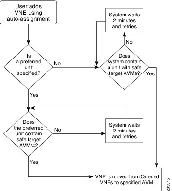
If Prime Network cannot locate an appropriate AVM, it waits 2 minutes and tries again. It will continue retrying until an AVM is found. Note that even when you use the auto-add feature, before the VNEs are created, you can choose a unit or AVM for a drop-down list in the VNE properties dialog.
Figure 4-3 illustrates how Prime Network identifies the best AVM and unit in the auto-add process.
Figure 4-3 VNE Auto-Add
Clone an Existing Device
A clone VNE inherits all of the properties of an existing VNE (including the Device Package being used by the existing VNE). You only have to specify a different name and IP address. Prime Network will choose the best unit and AVM for the VNE, but you can override this with your own choice. Once you have created the clone VNEs, you can still edit their properties before creating them.
Before You Begin
Make sure you have performed any required tasks that are described in Steps and Required Information for Adding VNEs. This will ensure that the VNE is properly modeled and updated.
Step 1
Prime Network chooses the unit and AVM
From All Servers in the navigation area, click All VNEs tab.
Prime Network chooses the AVM but you choose the unit
From desired unit in the navigation area, click Unit's VNEs tab.
You choose the unit and AVM
From desired unit in the navigation area, click the desired AVM
Step 2
Step 3
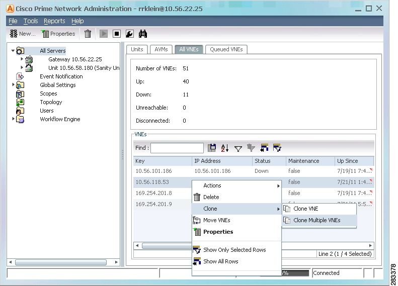
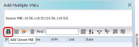
In Figure 4-4, the user is creating several clone VNEs based on the VNE with the key (name) 10.56.118.53. Because the action was performed while the All Servers branch is selected, Prime Network will choose the appropriate unit and AVM.
Figure 4-4 Creating a Clone VNE Using Auto-Add—Selecting the VNE
Step 4
a.
Figure 4-5 Creating a Clone VNE Using Auto-Add—Creating the Clones
A Clone VNE dialog box is displayed. It contains all of the properties of the target VNE except for the VNE name and IP address.
b.
Note
c.
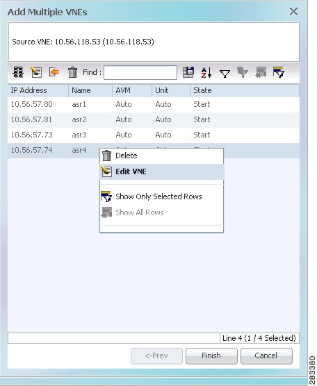
Step 5
Figure 4-6 Creating a Clone VNE Using Auto-Add—Viewing and Editing the Clones
Step 6
a.
b.
c.
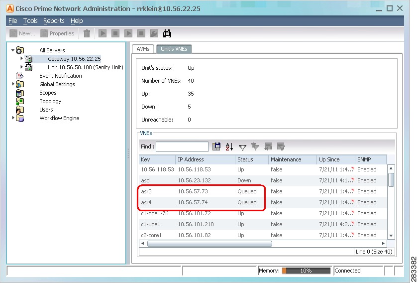
Figure 4-7 shows two new VNEs that were added to the gateway but are using AVM auto-assignment. Their assignment is pending.
Figure 4-7 Creating a Clone VNE Using Auto-Add—Checking the Assignment
Add a New Device Type
If you are creating a VNE for a new device type, you should create a single VNE instance "from scratch" and test it to ensure its settings are correct. You can then clone it as described in Clone an Existing Device.
Before You Begin
Make sure you have performed any required tasks in Steps and Required Information for Adding VNEs. This will ensure that the VNE is properly modeled and updated.
Step 1
Prime Network chooses the unit and AVM
All Servers > New VNE
Prime Network chooses the AVM but you choose the unit
Unit > New VNE
You choose the unit and AVM
Unit > AVM > New VNE
Step 2
General
Enter general information such as VNE name, IP address, and scheme. By default, Prime Network uses the newest DP installed on the gateway or unit. If you are creating a single VNE, you can specify a different DP from the drop-down list.
Note
SNMP
Specifies SNMP information and credentials to support polling and device reachability. The fields displayed in the dialog box depend on the protocol you select.
Telnet/SSH
Enables Telnet and SSH for device reachability and investigation, including the Telnet sequence and SSH prompts. The fields displayed in the dialog box depend on the protocol you select.
XML
Enables XML for device reachability and investigation.
HTTP
Enables HTTP or HTTPS for device reachability and investigation.
TL1
Enables the TL1 management protocol for running scripts on the device (used by Change and Configuration Management only).
ICMP
Enables ICMP and the ICMP polling rate (in seconds) for device reachability testing.
Polling
Associates a VNE with a previously created polling group or allows you to configure different polling settings according to the type of VNE information you want (status, configuration, and so forth).
Adaptive Polling
Controls how the VNE should respond to high CPU events.
Events
Specifies other IP addresses on which the VNE should listen for syslogs and traps.
vCenter
Enables connections to a Cisco UCS vCenter server using the HTTP or HTTPS communication protocol for vCenter reachability and investigation. (
Note
Step 3
a.
b.
c.
Add Devices Using Network Discovery
Note
The Network Discovery feature will automatically discover your network devices by traversing the network. Use this method if you are not very familiar with the types of devices in your network. The only required information is an IP address for a seed device, and the SNMPv 2 or SNMPv 3 credentials. This information is added to a discovery profile that specifies the IP and SNMP information, along with any additional protocols or filters you want Prime Network to use. You can use multiple discovery techniques in your filter in order to locate and discover the largest number of devices.
Once your profile is complete, run the discovery job. Prime Network will use its auto-add feature to assign VNEs to AVMs. When the job is finished, a result report provides a listing of devices that were successfully located, devices that were filtered out, and devices that reported credential errors. Prime Network will not create any VNEs until it receives confirmation to proceed. After the discovery job completes, you can instruct Prime Network to create VNEs for the devices that were successfully located. For the devices with credential errors, you can correct or create a new profile, or create the VNEs manually.
Note
Before You Begin
Make sure of the following:
•
•
Step 1
Step 2
•
•
•
•
Provide a unique name, and configure the discovery profile.
Discovery Technique
Methods Prime Network should use to discover devices. You can specify multiple techniques in order to locate and discover the largest number of devices
Ping Sweep
Instructs Prime Network to ping a range of IP addresses, and add any devices that respond to the ping. You must specify a seed device IP address and subnet mask to specify a range of IP addresses.
Note
Protocol Data Techniques
Instructs Prime Networkm to use other protocols to discover devices, and when a device is found, how many hops further to discover. You must specify a seed device IP address and the allowed number of hops from the device.
Note
Credential Settings
Pool of credentials Prime Network should use to communicate with and discover the devices. You can use SNMPv2, SNMPv3, Telnet, and SSH.
Note
Management IP Selection Method
Method the system should use to identify which device IP address should be used as the management IP address:
Discovered IP
This is default method. Use discovered IP as management IP address.
Loopback
If the IP address is a loopback, Ethernet, Token Ring, or Serial interface, use its highest IP address as the management IP address.
System Name
Perform a DNS lookup of the system name to verify the validity of the IP address, and:
•
•
DNS Reverse Lookup
Perform a reverse DNS lookup of the system name to verify the validity of the IP address, and:
•
•
Filters
(Optional) Criteria for including or excluding devices from the list of discovered devices.
System Location
Filter by physical/geographic location of the device as specified in the SYSTEM-MIB). If your network devices are configured with the system location, you can use this filter option.
Optional Filters
•
•
•
d.
Step 3
Step 4
Name
Discovery job name (profile name plus system-assigned number)
Status
Status of discovery job
Job is running or is completed with no credential errors
Job is running or completed and encountered credential errors. Consider running the job again or creating the VNE manually.
Job was aborted
Start Time,
End TimeStart and end time of discovery job
Discovery Profile
Name of profile being used by job
Reachable
Number of discovered devices that are reachable and manageable using the specified credentials (before creating the VNEs, you can change the VNE scheme and reduced polling setting; Step 5)
Filtered
Number of devices that were filtered out (for a list of these devices, click the Filtered tab at the bottom of the Discovery Results window)
Credential Error
Number of devices that were identified but could not be managed because of credential problems (for a list of these devices, click the Credential Errors tab at the bottom of the Discovery Results window)
Step 5
a.
b.
c.
Found
Device has been located.
In Progress
VNE creation process is starting.
Queued
VNE was created but has not yet been assigned to an AVM (in the Administration GUI client, they will show a status of Queued).
Naming Conflict
A VNE with that name or IP address already exists. (Correct it and try again.)
IP Conflict
Assigned
VNE was created and assigned to an AVM. You can check the AVM assignment by located the VNE is the Administration GUI client.
Add Devices Using a CSV File
Using a CSV file to add VNEs is helpful when you have a large number of VNEs to create and you want to organize your information using a spreadsheet template. After you create the spreadsheet, copy it to the gateway server, and then provide it as input to the Add Multiple VNEs dialog box. Prime Network will auto-add the VNEs—that is, it will choose the unit and AVMs for the VNEs. The new VNEs will use the latest installed DP (the newest DP that is installed on the gateway or unit). If there are any errors, Prime Network will clearly display them. If any fields are left blank, Prime Network uses the defaults specified in Table 4-6.
Format of a CSV File
The CSV file supports all of the entry names listed in Table 4-6. A general guideline is that you should supply the following entries in your file, at a minimum:
elementName,ip,SNMPEnabled,SnmpVersionEnum,adminStatusEnum
,SchemeName,avm,unitIP,ICMPPollingRate,ICMPEnabled,PollingGroup,TrapSyslogSources,TelnetSe
quence,telnetEnabled
The following is the text of a sample CSV file. This CSV file is also provided on the gateway server at NETWORKHOME/Main/scripts/BulkVNEImportExample.csv.
elementName,ip,SNMPEnabled,SnmpVersionEnum,adminStatusEnum
,SchemeName,avm,unitIP,ICMPPollingRate,ICMPEnabled,PollingGroup,TrapSyslogSources,TelnetSe
quence,telnetEnabled
m1,1.1.1.1,TRUE,1,0,ipcore ,,,50000000,TRUE,slow,,">,prompt,#,",TRUEm2,1.1.1.2,TRUE,2,1,product,,,856000,FALSE,default,,#,TRUEm3,1.1.1.3 ,TRUE,2,1,,,,,TRUE,,"129.5.6.2,55.23.6.5,9.5.2.1",">,text,#,",FALSEm4,1.1.1.4,TRUE,1,0,,,,,FALSE,,121.2.3.4,,TRUEm5,1.1.1.5,TRUE ,1,0, ipcore ,,,5600000,FALSE ,slow,121.2.3.4,">,admin,#,",FALSE
Table 4-6 Supported Values for CSV File (Creating VNEs)
elementName
Note
string or IP address
Mandatory field1
ip
vne IP address
Mandatory field
elementClassEnum
0=AutoDetect, 1=Generic SNMP, 2=Cloud, 3=ICMP
0 (AutoDetect)
SchemeName
default (= product), product, ipcore, ems, existing custom schemes
product
adminStatusEnum
0=Disabled (do not start VNE), 1=Enabled (start VNE)
1 (start VNE)2
avm
avm ID
(null) (Use auto-add)
unitIP
unit IP address
(null) (Use auto-add)
SNMPEnabled
TRUE=Enabled, FALSE=Disabled
TRUE
SnmpVersionEnum
0=SNMPv1, 1=SNMPv2, 2=SNMPv3
1 (SNMPv1)
SNMPReadCommunity
string
public
SNMPWriteCommunity
string
private
SnmpV3AuthenticationEnum
0=noauth, 1=auth_no_priv, 2=priv
0 (noauth)
SnmpV3AuthenticationUserProfile
string
(null)
SnmpV3AuthenticationPassword
string
(null)
SnmpV3AuthenticationProtocolEnum
0=md5, 1=sha
(null)
SnmpV3EncryptionPassword
string
(null)
SnmpV3EncryptionTypeEnum
0=des, 1=aes128, 2=aes192, 3=aes256
(null)
TelnetEnabled
TRUE=Enabled, FALSE=Disabled
FALSE
TelnetProtocolEnum
0=Telnet, 1=SSHv1, 2=SSHv2
0 (Telnet)
TelnetPortNumber
port-number
23 (Telnet), 22 (SSHv1/v2)
TelnetSequence
"sequence"(null)
SshCipherEnum
0=DES, 1=3DES, 2=Blowfish
1 (3DES)
SshAuthenticationEnum
0=password
0 (password)
SshV1Username
string
(null)
SshV1Password
string
(null)
SshV2Username
string
(null)
SshV2Password
string
(null)
XMLPortNumber
port-number
38751 (Telnet), 52 (SSL)
XmlProtocolEnum
0=Telnet, 1=SSL
0 (Telnet)
XMLEnabled
TRUE=Enabled, FALSE=Disabled
FALSE
XMLSequence
string
(null)
HTTPPortNumber
port-number
80
HttpProtocolEnum
0=HTTP, 1=HTTPS
0 (HTTP)
HTTPEnabled
TRUE=Enabled, FALSE=Disabled
FALSE
HTTPManagementPath
string
(null)
HTTPAuthenticationRequired
TRUE=Required, FALSE=Not required
FALSE
HTTPUserName
string
(null)
HTTPPassword
string
(null)
TL1Enabled
TRUE=Enabled, FALSE=Disabled
FALSE
TL1PortNumber
port-number
(null)
TL1Username
string
(null)
TL1Password
string
(null)
ClientAuthEnum
0=password, 1=public
0 (password)
ClientPrivateKey
string
(null)
ServerAuthEnum
0=none, 1=save-first-auth, 2=preconfigured
2 (preconfigured)
ServerPublicKey
string
(null)
FingerPrint
string
(null)
ServerAuthDataTypeEnum
0=fingerprint, 1=public-key
0 (fingerprint)
KeyExchange
string
(null)
MAC
0=sha1, 1=md5, 2=sha1-96, 3=md5-96
(null)
Cipher
0-3DES, 1=AES-128, 2=AES-192, 3=AES-256
(null)
HostKeyAlgo
0-DSA, 1=RSA
(null)
IsActionNotAllowed
TRUE=Not allowed, FALSE=Allowed
(null)
ICMPEnabled
TRUE=Enabled, FALSE=Disabled
FALSE
ICMPPollingRate
number (milliseconds)
(null)
PollingGroup
slow, default
default
AdaptivePollingSettingEnum
0=Prime Network Settings, 1=Device Type Settings, 2=Local Settings
1 (Device Type Settings)
TrapSyslogSources
"IP address[,IP address,...]"(null)
1 For existing VNEs, you cannot overwrite the VNE name or IP address using a CSV file. To change a VNE name or IP address you must delete the existing VNE and create a new one.
2 If you use auto-add, the VNE will automatically be started regardless of this setting.
3 These settings are not used by VNEs provided with the initial release of Prime Network 3.10. Future Device Packages will introduce new device support for devices that will use this feature.
Before You Begin
Make sure you have performed any necessary tasks that are described in Steps and Required Information for Adding VNEs. This will ensure that the VNE is properly modeled and updated.
Step 1
Step 2
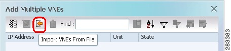
a.
Figure 4-8 Creating VNEs from a CSV File—Selecting the CSV File
b.
Red text indicates a conflict with an existing VNE. Fix the problem by proceeding to the next step.
Step 3
Note
Step 4
a.
b.
c.
Add New Device Support by Installing Device Packages
These topics explain how to extend Prime Network NE support using the Device Package mechanism, including how to use the ivne script to install and manage DPs:
•
•
•
•
•
Note
Device Packages are downloadable packages that contain a group of VNE driver jar files. When you add a device to Prime Network, Prime Network identifies the NE by vendor, device family, device subfamily, device type and software version. This is done by matching the device with its appropriate VNE driver jar file. The driver jar file contains information about software versions, physical and logical entities, syslogs, traps, and activation scripts, all of which enable Prime Network to properly model and monitor the device.
Between releases of Prime Network, updates to driver jar files are packaged together and delivered in Device Packages (DPs). As new DPs become available, the DP and its Readme file are placed on the Prime Network Software Download site on Cisco.com, and the new support is documented in the Addendum: Additional VNE Driver Support for Cisco Prime Network 3.10. Once you download a Device Package, you can install it using the ivne script. Once a DP is installed, if you right-click a VNE and choose Update VNE Device Package, the new DP is listed along will available DPs.
Understanding Version Numbers in VNE Driver Jar Files and DPs
VNE driver jar files are cumulative and contain all the enhancements that are provided in earlier versions. All jar files use the following versioning practice:
Vendor-JarType-VNEJarVersion.jar
JarType can be Modules, Commons, or device-specific. For example:
Cisco-Commons-v1.0.0.0.jar
First release of jar file with support common to all Cisco devices.
Cisco-Modules-v1.0.0.0.jar
First release of jar file with support common to all Cisco modules.
Cisco-ASR90xx-v2.0.0.0.jar
Second release of jar file with support common to all ASR 9000 Series Aggregation Services Routers. Contains all of the support provided in version 1.0.0.0.
Cisco-3750ME-v1.0.0.0.jar
First release of jar file with support common to all Cisco Catalyst 3750 Metro Series Switches.
Similarly, DPs contain the latest version of all available jars. Even if a jar is not revised for a DP, it is still included in to ensure that all available enhancements are installed. After installing a DP using the ivne script, no changes are applied to a VNE until you restart it.
Prime Network 3.10 DPs use the following versioning practice:
PrimeNetwork-3.10-DPyymm
For example, PrimeNetwork-3.10-DP1212 is the December 2012 DP for Prime Network 3.10.
Find Out if New Device Support is Available
When a new DP is released, the new support is documented in Addendum: Additional VNE Driver Support for Cisco Prime Network 3.10. The addendum is a companion guide to the Cisco Prime Network 3.10 Supported Cisco VNEs and other supported documents on Cisco.com, which lists the support provided with the base release.
There are DP-specific documents that describe the DP contents and how to install the DP. They are provided with the DP on the Prime Network Software Download site (thus they are available when the the first DP is released):
•
•
Identify Which DPs Are Installed on the Gateway
This procedure explains how to find out which DP and jar files are installed on the gateway server in NETWORKHOME/Main/drivers. Many different versions of DP can be installed at one time and many of them may not be being used.
By default, when a VNE is restarted, it uses the latest DP installed on the gateway or unit. Prime Network will detect the device type and identify the newest DP for that device type (for both Cisco and non-Cisco devices). You can also choose a different driver at a later time as described in Change the Device Package a VNE Is Using.
Note
Step 1
Note
Invalid value for width: 80, it means the terminal window is not wide enough. Enlarge the window and try again.# ivne ------------------------------------------------------------------------------| Cisco Prime Network VNE Device Package Installer------------------------------------------------------------------------------| 1 | Install VNE Device Package from a local directory| 2 | Install VNE Device Package from a Web repository| 3 | List installed Device Packages| 4 | Show latest installed Device Packages| 5 | Uninstall a Device Package| q | Quit------------------------------------------------------------------------------Step 2
-----------------------------------------------------------------------------| Select Device Package (DP) to display the included drivers.-----------------------------------------------------------------------------| 1 | PrimeNetwork-3.10-DP0| 2 | PrimeNetwork-3.10-DP1301| 3 | PrimeNetwork-3.10-DP1302| 4 | PrimeNetwork-3.10-DP1303| 5 | PrimeNetwork-3.10-TPDP1303| 6 | Back-----------------------------------------------------------------------------The script lists the contents of the specified DP, as in the following example:
Gathering information from /export/home/pn310/Main/drivers/Name Driver File Name Version Device PackageCisco-100xx-PN3.10 Cisco-100xx-v4.0.0.0.jar 4.0.0.0 PrimeNetwork-3.10-DP0Cisco-12xxx-PN3.10 Cisco-12xxx-v4.0.0.0.jar 4.0.0.0 PrimeNetwork-3.10-DP0Cisco-3400ME-PN3.10 Cisco-3400ME-v4.0.0.0.jar 4.0.0.0 PrimeNetwork-3.10-DP0Step 3
-----------------------------------------------------------------------------| Latest installed device packages.-----------------------------------------------------------------------------| | PrimeNetwork-3.10-DP1212| | PrimeNetwork-3.10-TPDP1212| b | Back-----------------------------------------------------------------------------No further information is displayed. Click Back to return to the main ivne menu.
Note
Identify Which Driver a VNE Is Using
When a VNE is created, it checks the gateway for the most recent DP and uses the applicable driver from that DP. DPs are installed on the gateway server in NETWORKHOME/Main/drivers. You can specify a different DP when you create the VNE, or by updating the VNE (see Change the Device Package a VNE Is Using).
The VNEs table displays the device driver file and version that VNEs are using. Figure 4-9 illustrates the driver jar file information that is shown when you list all VNEs. This information is also provided on the VNE properties page.
Figure 4-9 VNE Driver Jar File Name (By Selecting AVM in Navigation Pane)
To find out if a newer device driver is available, check the Addendum: Additional VNE Driver Support for Cisco Prime Network 3.10. That document becomes available when the Prime Network DP is published. The "New Support" section lists all new functionality that is available via DP. If new support is available, download and install the DP as described in Download and Install New Driver Files.
Change the Device Package a VNE Is Using
The update function allows you to choose from all DPs that are installed on the gateway or unit, and apply a DP's corresponding jar file to a VNE. You can choose an earlier DP, effectively rolling back to an earlier driver installation. You must restart the VNE for the changes to take effect.
Tip
Choosing latest means Prime Network will detect the device type and identify the newest DP for the device type (for both Cisco and non-Cisco devices).
Step 1
•
•
Step 2
latest
PrimeNetwork-3.10-DP1302
PrimeNetwork-3.10-DP1301
PrimeNetwork-3.10-DP1212
In this example, latest corresponds to DP1303 (the March 2013 Device Package).
Step 3
Step 4
Download and Install New Driver Files
Use this procedure to download and install new driver files to your gateway server. The new drivers are not applied until you restart the VNEs.
1.
Check the documentation for new support, and run a report to identify which VNEs should be updated.
2.
Download the Device Package tar file according to the instructions on the download site.
3.
Download the DP installation instructions use ivne to install the DP.
4.
Apply the new drivers to the VNEs.
Prepare to Install a New VNE Device Package
Step 1
Step 2
Step 3
•
•
Download the Device Package
For the current instructions on downloading the DP, use the documentation that is on the download site. This procedure explains how to get the documentation.
Step 1
Step 2
Step 3
Step 4
Install the Device Package Using ivne
The ivne script installs DP on the gateway server. The changes are not applied to the VNEs until they are restarted. If any new drivers depend on the support provided in other driver, those jar files are also installed.
Step 1
Step 2
# ivne---------------------------------------------------------------------------------| Cisco Prime Network VNE Device Package Installer---------------------------------------------------------------------------------| 1 | Install VNE Device Package from a local directory| 2 | Install VNE Device Package from a Web repository| 3 | List installed Device Packages| 4 | Show latest installed Device Packages| 5 | Uninstall a Device Package| q | Quit---------------------------------------------------------------------------------Step 3
•
•
The script creates an installation log file in NETWORKHOME/Main/drivers/log/ivne-install-log-mmddyy-hhmmss.
Step 4
1 (install from tar file)
Enter the full pathname.
2 (install from web repository)
Enter the repository address in one of these formats:
IP-address/full-pathname-to-DP-repository
hostname/full-pathname-to-DP-repositoryExample: 120.56.57.58/drivers
If you use the web repository method and receive an error message, do the following:
•
•
•
Restart the VNEs to Apply the New Driver Files
Click the All VNE tab to view the VNEs table. You can restart individual or groups of VNEs by right-clicking the VNEs and selecting Actions > Stop. When the status changes to Down, right-click the VNEs and select Actions > Start.
Uninstall a Device Package
A DP uninstallation removes the DP from the gateway. Any VNEs using the DP will have to be updated to use a different DP.
Step 1
Step 2
Step 3
# ivne---------------------------------------------------------------------------------| Cisco Prime Network VNE Device Package Installer---------------------------------------------------------------------------------| 1 | Install VNE Device Package from a local directory| 2 | Install VNE Device Package from a Web repository| 3 | List installed Device Packages| 4 | Show latest installed Device Packages| 5 | Uninstall a Device Package| q | Quit---------------------------------------------------------------------------------Step 4
----------------------------------------------------------------------------------| Select Device Package (DP) to display the included drivers.----------------------------------------------------------------------------------| 1 | PrimeNetwork-3.10-DP0| 2 | PrimeNetwork-3.10-DP1212| 3 | PrimeNetwork-3.10-DP1301| 4 | PrimeNetwork-3.10-DP1302| 5 | Back----------------------------------------------------------------------------------Step 5
Change a VNE IP Address and Other VNE Properties
You can edit many of a VNE's properties, such as the IP address, by making changes in the VNE's Properties dialog box, and then stopping and restarting the VNE. The VNE type determines which properties you can edit. For example, you can only edit General settings for Cloud VNEs; for ICMP type VNEs, you cannot edit Polling settings. If you cannot change the desired property, you must create a new VNE.
To change a VNE's properties, right-click the VNE and select Properties to open the Properties dialog box. When you finish making your change, stop and restart the VNE. See these topics for more information:
•
for example, if a device is generating configuration change events but Prime Network is not recognizing them, edit the VNE properties (Events tab) and add the IP address you want the VNE to listen to. See VNE Properties: Events.
•
•
Some VNE characteristics are controlled by global settings that affect all or groups of VNEs. Some of these can be changed using the Administration GUI client, while others require changes to the registry. These topics describe how to change VNE behavior and properties, and where to get more information:
Table 4-7 Making Advanced Changes to VNEs
Adjust VNE polling settings, such as:
•
•
•
•
Change the criteria Prime Network uses to designate the Unreachable and Partially Reachable VNE investigation states
Change how device registration commands (that discover and model the devices) are executed
Change How VNE Commands Are Executed (Collectors Command and Priorities)
Adjust the alarm, modeling, and topology data that is saved across VNE restarts
Create a Cloud VNEs to represent an unmanaged network segment (so alarms can still be correlated and information can be passed across the segment)
Create Connections for Unmanaged Network Segments (Cloud VNEs and Links)
Adjust the rate at which VNEs initiate Telnet/SSH connections across the network (to prevent degraded performance on servers such as TACACS)
Change a VNE IP Address
You can change a VNE's IP address by editing its properties and restarting the VNE. Keep the following in mind:
•
•
See Manage Duplicate IP Addresses for information on how Prime Network manages networks in which VNEs have the same IP address.
Note
Step 1
Step 2
a.
b.
Step 3
Step 4
Step 5
Manage Duplicate IP Addresses
Note
Prime Network can manage networks where two VNEs have the same IP address. If your network has only a single domain, you do not have to perform any extra configuration steps.
For networks with multiple domains, you may have to perform special steps to make sure that Prime Network correctly associate VNEs with their IP addresses. This ensures that Prime Network will properly model the device topology and correlate device alarms. The need to perform extra steps depends on:
•
•
If the IP addresses are used only as management IPs, and your network is configured with static NAT, you do not have to perform any extra steps when creating two VNEs with the same IP address. Prime Network will treat the two IP addresses as unique addresses.
Table 4-8 shows the scenarios in which Prime Network can support two VNEs with the same IP address, along with the required configurations you may have to perform for each scenario.
Table 4-8 Supported Scenarios: for Two VNEs with the Same IP Address
If the network has static NAT, no special configurations are required when creating two VNEs
If the network has static NAT, do one of the following to the two VNEs:
•
•
If the network does not have static NAT, place the two VNEs on different units
If the network does not have static NAT, do one of the following to the two VNEs:
•
•
Configure Domain IDs on VNEs
This procedure shows you how to retrieve and set a domain ID on a VNE. If a device spans multiple domains, you can configure the VNE with multiple domain IDs.
Step 1
# cd $ANAHOME/Main
Step 2
# ./runRegTool.sh -gs 127.0.0.1 get unit-ip avmxxx/agents/da/vne-key/topologyDomainsId
This example retrieves the domain ID from a VNE named c1-npe1-76 which resides on AVM 850 on the gateway server.
# ./runRegTool.sh -gs 127.0.0.1 get 127.0.0.1 "avm850/agents/da/c1-npe1-76/topologyDomainsId"101#Step 3
# ./runRegTool.sh -gs 127.0.0.1 get unit-ip avmxxx/agents/da/vne-key/topologyDomainsId
This example sets a domain ID of 101 on the VNE c1-npe1-76:
# ./runRegTool.sh -gs 127.0.0.1 set 127.0.0.1 "avm850/agents/da/c1-npe1-76/topologyDomainsId" 101
success
To set multiple domains on the VNE c1-npe1-76 (for example, the device bridges over multiple domains):
# ./runRegTool.sh -gs 127.0.0.1 set 127.0.0.1 "avm850/agents/da/c1-npe1-76/topologyDomainsId" "101,102"
success
Configure Domain IDs on Units
This procedure shows you how to retrieve and set a domain ID on a unit.
Step 1
# cd $ANAHOME/Main
Step 2
# ./runRegTool.sh -gs 127.0.0.1 get unit-ip agentdefaults/da/topologyDomainsIdThis example retrieves the domain ID from a unit with the IP address 192.0.2.0 (in this example, no domain ID is set on the unit):
# ./runRegTool.sh -gs 127.0.0.1 get 192.0.2.0 agentdefaults/agents/da/topologyDomainsIdnull#Step 3
# ./runRegTool.sh -gs 127.0.0.1 set 192.0.2.0 agentdefaults/agents/da/topologyDomainsId
101
success
Move VNEs to Another AVM
The AVM load balancing feature monitors AVM memory usage, signals when a VNE should be moved from an AVM (so that memory usage is not exceeded), and suggests which AVM the VNE should be moved to. Because this feature is automated, you should rarely have to move VNEs on your own, apart from this feature. (See Manage AVM Memory and Thresholds (Load Balancing).)
However, if you do need to move VNEs to different AVMs, you can certainly do so. When you move VNEs between different AVMs, the VNEs retain their original status, except for VNEs that were in maintenance mode. Those VNEs will be moved out of Maintenance and into the Down status.
Note
To move one or more VNEs:
Step 1
Step 2
Step 3
Step 4
Step 5
You can verify that the VNE has been moved by selecting the appropriate AVM in the navigation tree and viewing the moved VNE in the VNEs Properties table.
Delete VNEs
When you delete a running VNE from a unit and AVM, the VNE is stopped and all VNE references are deleted from the system and registry. A VNE that has been removed no longer appears in any future system reports.
Note
When you delete a VNE, you also delete all Layer 3 VPN site and virtual router business element data associated with the VNE. You can delete business elements separately by using Prime Network Vision. For more information about deleting business elements using Prime Network Vision, see the Cisco Prime Network 3.10 User Guide.
Since all VNE information is deleted, adding the VNE again requires you to reenter all VNE information.
Note
To delete a VNE:
Step 1
Step 2
Step 3
Step 4
•
•
). To remove these orphaned business elements, delete them manually in Prime Network Vision.
•
Step 5
Remove the following files, where avm-id is the AVM hosting the VNE, and vne-ip is the IP address of the VNE that was removed. (Note that you should remove all files and directories in the instrumentor-persistency directory.)
$ANAHOME/unit/avm-id/persistency/alarm/vne-ip.per
$ANAHOME/unit/avm-id/persistency/event/vne-ip.per
$ANAHOME/unit/avm-id/instrumentor-persistency/vne-ip/*
Troubleshoot Device Connectivity Issues (VNE Communication States)
These topics help you understand how Prime Network determines connectivity and how to troubleshoot common connectivity problems.
•
•
What Determines the VNE Communication State (Device Reachability)?
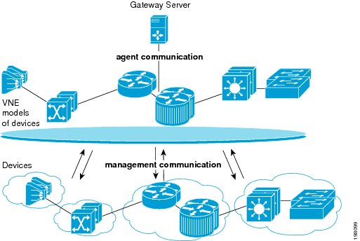
Figure 4-10 illustrate the two aspects that determine a VNE's communication state: agent communication, which describes reachability between the Prime Network gateway server and the VNEs, and management communication, which describes the reachability between a Prime Network VNE and the network device it is modeling. Both must function in order for Prime Network to properly model and manage a device.
Figure 4-10 VNE Communication States—Management and Agent
Management communication is the more challenging domain because devices commonly go down; VNEs do not. But there can be different degrees to which a device is down. Perhaps only the Telnet protocol is down but everything else is fine; or all protocols are down but the device is still "alive" (sending syslogs and traps); or all protocols down, and the device is not even generating traps or syslogs.
To provide the most accurate reachability status, Prime Network does the following:
•
•
•
•
For details about how Prime Network does all of the above, see Change Settings That Determine Device Reachability.
The most common management problem is when Prime Network reports that a VNE communication state is Device Partially Reachable because at least one protocol is not operational. To help in these situations, the VNE Status Details window often provides valuable information to help you solve the problem. Table 4-10 provides information about the fields in the VNE Status Details window, and suggestions for troubleshooting steps based on the information you see.
When a VNE's communication state changes, Prime Network generates a Service event. For newly-added VNEs, an event is generated only after all protocols have been tested. Reachability-related events are also correlated to each other and to any relevant tickets on the managed device. New events will also be correlated to the relevant ticket.
If a Service event indicates a possible problem, check the event details, which may have valuable information about the device problem. For example, a Device Unreachable event could signal a device protocol problem, or it could indicate that a VNE was shut down as part of normal maintenance.
Note
Steps to Troubleshoot VNE Communication State Issues
Use this procedure to troubleshoot an unexpected VNE communication state.
1
Verify the current VNE communication (and investigation) states in Prime Network Vision.
2
Check the VNE Status Details window to find out if any protocols are failing and why; and check the management communication policy that is being used.You can optionally check the Service event to see if it can provide any new information.
Step 2: Check the VNE Status Details Window for Protocol and Connectivity Information
3
Test the protocol connectivity.
Step 1: Check the Communication State
Step 1
Note
Step 2
Figure 4-11 VNE Communication State (in Prime Network Vision)
The
icon indicates a network element has been deleted (or moved).
Note the state and refer to Table 4-2, which explains why a VNE may be in that state and how to proceed.
Table 4-9 VNE Communication States and Troubleshooting Tips
Agent Not Loaded
The VNE is not responding to the gateway because it was stopped, or it was just created. This communication state is the equivalent of the Defined Not Started investigation state. To troubleshoot a VNE in this state, check the VNE, AVM, and unit status using Prime Network Administration.
Although a Service event is generated whenever the communication state changes, when a VNE is started, an event is generated only after:
•
•
Note
None
VNE/Agent Unreachable
The VNE is not responding to the gateway. This can happen if the unit or AVM is overutilized, the connection between the gateway and unit or AVM was lost, or the VNE is not responding in a timely fashion. (A VNE in this state does not mean the device is down; it might still be processing network traffic.) To troubleshoot a VNE in this state:
1.
2.
3.
Connecting
The VNE is starting and the initial connection has not yet been made to the device. This is a momentary state. Because the investigation state decorator (the hourglass) will already be displayed, a special GUI decorator is not required.
None
Device Partially Reachable
The element is not fully reachable because at least one protocol is not operational. To troubleshoot this state, continue to Step 2: Check the VNE Status Details Window for Protocol and Connectivity Information.
Note
Device Reachable
All element protocols are enabled and connected.
Note
None
Device Unreachable
The connection between the VNE and the device id down because all of the enabled protocols are down (though the device might be sending traps or syslogs). To troubleshoot this state, continue to Step 2: Check the VNE Status Details Window for Protocol and Connectivity Information.
Note
Tracking Disabled
The reachability detection process is not enabled for any of the protocols used by the VNE (specifically, the trackreachability registry key is not set to true; see Change How Protocols are Tested for Reachability). The VNE will not perform reachability tests nor will Cisco Prime Network generate reachability-related events. In some cases this is desirable; for example, tracking for Cloud VNEs should be disabled because Cloud VNEs represent unmanaged network segments.
Because this is a user-defined mode (rather than an error or transitional mode), Cisco Prime Network does not display a decorator for this state. To troubleshoot this state, continue to Step 2: Check the VNE Status Details Window for Protocol and Connectivity Information.
None
Step 2: Check the VNE Status Details Window for Protocol and Connectivity Information
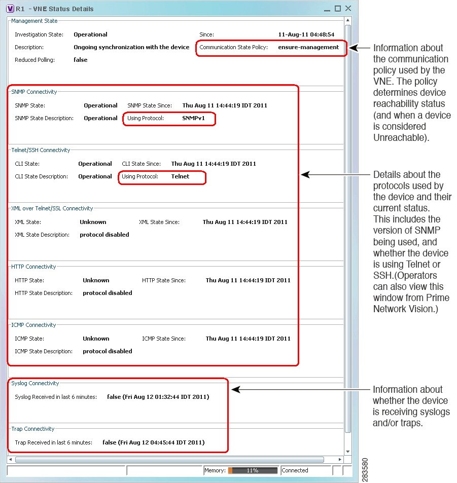
Step 1
For an example of a VNE with communication problems, see Figure 4-13.
Figure 4-12 VNE Status Details Window
Table 4-10 provides a description of the fields in the window.
Table 4-10 VNE Communication State Information (from VNE Status Details Window)
The current investigation state, which pertains to device modeling (not communication). For an explanation of the Investigation State, Description, and Reduced Polling fields, see Table 4-12.
Since
Timestamp of when the management state fields were last updated.
Communication State Policy
Policy being used by Prime Network to determine device reachability and when to change the communication state to Device Unreachable.
notstrict
Change state to Device Unreachable when:
•
•
Change state to Device Partially Reachable when:
•
•
ensure-
managementChange state to Device Unreachable when:
•
The status of traps/syslogs is not considered. This is the default policy.
strict
Change state to Device Unreachable when:
•
The status of traps/syslogs is not considered. (Because the state goes directly to Device Unreachable, you will never see the Device Partially Reachable communication state when using this policy.)
State
Functional state of the protocol (see the State Description for more details):
•
•
•
•
State Description
Details about the protocol state. Though problems can be due to a variety of issues, the following messages are grouped together by likely cause.
•
Protocol failed to login
Protocol failed to get first prompt
Protocol failed to login when sending leading CR
Protocol failed to get expected prompt
Protocol failed to initiate login
Protocol login authorization refused
Protocol login authorization timeout
Authentication failed•
Protocol failed to handle connection
Protocol failed to connect to host
Problem trying to ping host
Destination host unreachable•
Protocol failed to send command
Protocol says: Command authorization failed
Command execution exceptionState Since
Timestamp of when the protocol information was last updated.
Using Protocol
(Telnet/SSH Connectivity Only) Whether VNE is using Telnet or SSH. This provides an easy way for operators to check which protocol is being used.
Syslog/Trap received in last 6 minutes
Tells you whether the device is sending traps or syslogs (an indication of whether the device is still "alive"). The format is value (time), where:
•
•
For example:
false (Mon Jul 19 23:03:33 PDT 2012) means the VNE has not received any syslogs or traps since the time and date listed.
true (Tue Jul 20 05:09:25 PDT 2012) means the VNE has been receiving syslogs or traps at least every 6 minutes since the time and date listed.
If this field is blank, either no syslogs or traps were sent since the VNE was started, or Prime Network is using a management policy that does not track syslogs and traps.
If syslogs or traps are not arriving, do the following:
1.
2.
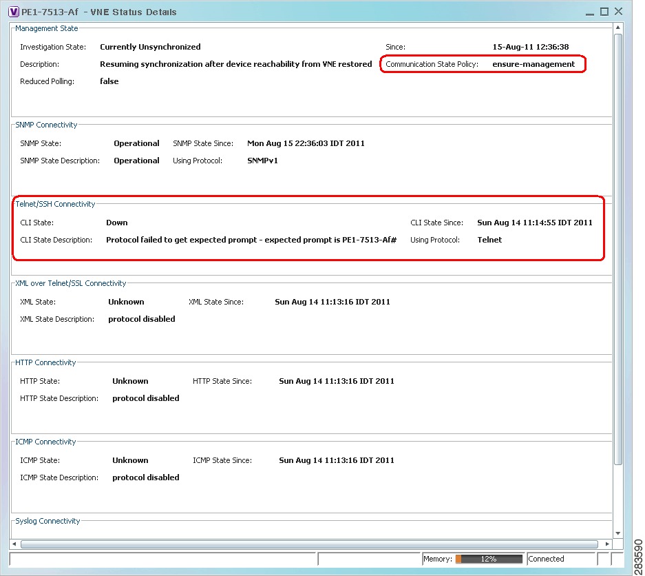
Figure 4-13 shows a VNE Status Details window for a VNE that is only partially reachable.
Figure 4-13 Communication State Information in VNE Status Details Window
Figure 4-13 provides the following information:
•
•
Step 2
Note
If you want more information, you can adjust the registry setting so that Prime Network Events generates an elaborated report about state changes. See Table 4-10.
Step 3: Troubleshoot the Connectivity Issue
Before you begin these steps, get the following information in order to avoid common mistakes that are made when checking VNE connectivity.
•
–
–
•
Follow this procedure to troubleshoot the connectivity problem. Some steps may not apply, depending on your configuration.
Step 1
Step 2
[64] collector failed to get expected prompt Password: after sending command adminStep 3
a.
# cd $ANAHOME/Mainb.
If the VNE is on the gateway server, the unit-IP should be 127.0.0.1.
If the VNE is not on the gateway server, the unit-IP should be the unit's IP address.# ./runRegTool.sh -gs 127.0.0.1 set unit-IP "avmxxx/agents/da/vne-key/ips/vne-ip/protocols/telnet/line-terminator "\r"c.
Step 4
a.
–
c7-npe1-76#show ip sshSSH Enabled - version 2.0Authentication timeout: 120 secs; Authentication retries: 3c7-npe1-76#–
SSH 2.x
SSHv2
SSH 1.x
SSHv1
SSH 1.99
SSHv2 and earlier
b.
Note
–
Note
–
If you cannot connect to the device, the likely source of the problem is something in your local configuration. Possible causes you can investigate are:
•
–
–
•
–
–
–
If you can connect to the device, the likely cause of the problem is that the VNE driver was not correctly implemented. Check the Cisco Bug Toolkit for possible open caveats, or open a bug as explained in Opening a Bug Report.
Step 5
a.
# cd $ANAHOME/Mainb.
If the VNE is on the gateway server, the unit-IP should be 127.0.0.1.
If the VNE is not on the gateway server, the unit-IP should be the unit's IP address.# ./runRegTool.sh -gs 127.0.0.1 set unit-IP "avmxxx/agents/da/vne-key/ips/vne-ip/protocols/telnet/connection/explicitly-ask-for-pt y" true# ./runRegTool.sh -gs 127.0.0.1 add unit-IP "avmxxx/agents/da/vne-key/ips/vne-ip/protocols/telnet/connection/transport"# ./runRegTool.sh -gs 127.0.0.1 set unit-IP "avmxxx/agents/da/vne-key/ips/vne-ip/protocols/telnet/connection/transport/pty-support " enable# ./runRegTool.sh -gs 127.0.0.1 set unit-IP "avmxxx/agents/da/vne-key/ips/vne-ip/protocols/telnet/telnet-over-sshv1/leadingcrenabl ed" false# ./runRegTool.sh -gs 127.0.0.1 set unit-IP "avmxxx/agents/da/vne-key/ips/vne-ip/protocols/telnet/telnet-over-sshv2/leadingcrenabled" falsec.
If you need more information about protocols and the tests and settings Prime Network uses to determine reachability, see Protocol Reachability Tests.
Troubleshoot Device Modeling Issues (VNE Investigation States)
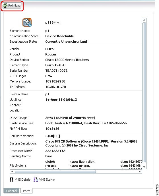
The Administration and Vision GUI clients provide a Poll Now tool for rediscovering a network element or an NE component. The launch point determines the entity that is rediscovered. If you right-click a device and choose Poll Now, the whole device is rediscovered. If you right-click a device component and choose Poll Now (from the inventory window), only the component is rediscovered. Vision GUI client users must have Operator privileges to use this feature.
Figure 4-14 shows the device inventory window with the Poll Now button at the top left. When launched from this window, the entire device is rediscovered. Although the Poll Now button is provided for use by all VNEs, it is specifically useful for VNEs using reduced polling because it provides a quick way to synchronize the VNE model without having to wait for the next polling cycle.
Figure 4-14 Poll Now Button in Prime Network Device Inventory
Use this procedure to troubleshoot an unexpected VNE investigation state.
1
Verify the current VNE investigation (and communication) states in Prime Network Vision.
2
Check the investigation state description in the VNE Status Details window, especially if you are seeing the Currently Unsynchronized state. You can optionally check the Service event to see if it can provide any new information.
Step 2: Check the VNE Status Details for the Cause of the Modeling Problem
3
If needed, perform these additional steps depending on the information you need:
•
•
•
•
Step 3: Additional Troubleshooting Steps for Investigation State Problems
Note
Step 1: Check the Investigation State
Step 1
Note
Step 2
Figure 4-15 VNE Investigation State (in Prime Network Vision)
Table 4-11 VNE Investigation States
Defined Not Started
A new VNE was created (and is starting); or an existing VNE was stopped. In this state, the VNE is managed and is validating support for the device type. (This investigation state is the equivalent of the Agent Not Loaded communication state.) A VNE remains in this state until it is started (or restarted). In the VNE Status Details window, the description will say VNE is down.
None
Unsupported
The device type is either not supported by Prime Network or is misconfigured (it is using the wrong scheme, or is using reduced polling but the device does not support it). See Table 4-12 for troubleshooting steps.
Discovering
The VNE is building the model of the device (the device type was found and is supported by Cisco Prime Network). A VNE remains in this state until all device commands are successfully executed at least once, or until there is a discovery timeout. In the VNE Status Details window, the description will say Initial investigation of the device.
To troubleshoot a VNE that does not move out of this state, perform the following steps:
1.
2.
3.
4.
The default discovery timeout is 30 minutes but you can adjust it. To change the timeout, see Registry Settings for VNE Discovery Timeout and Investigation State Reporting.
Operational
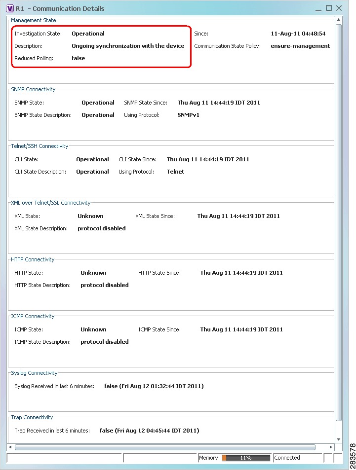
The VNE has a stable model of the device. Modeling may not be fully complete, but there is enough information to monitor the device and make its data available to other applications, such as activation scripts. A VNE remains in this state unless it is stopped or moved to the maintenance state, or there are device errors. In the VNE Status Details window, the description will say Ongoing synchronization with the device.
None
Currently Unsynchronized
The VNE model is inconsistent with the device. This can be due to a variety of reasons; check the VNE Status Details window can provide more information (see Step 2: Check the VNE Status Details for the Cause of the Modeling Problem).
Maintenance
VNE polling was suspended because it was manually moved to this state. In the VNE Status Details window, the description will say Device synchronization was suspended by user or system. The VNE remains in this state until it is manually restarted. A VNE in the maintenance state has the following characteristics:
•
•
•
•
The VNE is moved to the Stopped state if: it is VNE is moved, the parent AVM is moved or restarted, the parent unit switches to a standby unit, or the gateway is restarted.
Partially Discovered
The VNE model is inconsistent with the device because a required device command failed, even after repeated retries. A common cause of this state is that the device contains an unsupported module. See Table 4-12 for troubleshooting steps.
Shutting Down
The VNE has been stopped or deleted by the user, and the VNE is terminating its connection to the device. The VNE Status Details window, the description will say Device synchronization aborted.
Stopped
The VNE process has terminated; it will immediately move to Defined Not Started.
None
Step 2: Check the VNE Status Details for the Cause of the Modeling Problem
Step 1
Figure 4-16 Investigation State Information in VNE Status Details Window
Table 4-12 VNE Investigation State Information (from VNE Status Details Window)
Investigation State
VNE investigation state. Basic descriptions of all of the investigation states is provided in Table 4-3.
Description: Unsupported
The device type is either not supported by Prime Network or is misconfigured (it is using the wrong scheme, or is using reduced polling but the device does not support it). T his is the probable message you will see:
•
–
–
–
If the device type is not supported:
–
–
Description: Currently Unsynchronized
The VNE model is inconsistent with the device. This is often recoverable or may indicate a small inconsistency such as a minor inventory component not being properly modeled. These are some of the messages you may see for this state:
•
•
•
•
•
•
•
•
•
The Currently Unsynchronized state can also be caused by a communication state issue. See Steps to Troubleshoot VNE Communication State Issues.
Description: Partially Discovered
Missing or failed VNE driver component—Prime Network could not recognize an element in the device. Consider the following troubleshooting options:
•
•
Reduced Polling
Reports whether VNE is using reduced polling mechanism to control polling (true=enabled). Reduced polling means polling is performed only when a poll-worthy event is received from device, thus reducing the overall polling (true if enabled, false if disabled). For information on the reduced polling mechanism, see Reduced Polling.
Since
Timestamp of when the state information was last updated.
For information on the communication state details that are provided in this window, see Table 4-10.
Step 2
Note
Step 3: Additional Troubleshooting Steps for Investigation State Problems
Step 1
Step 2
Step 3
•
•
Opening a Bug Report
After performing the troubleshooting steps in the previous sections, if you still have a problem, you may consider opening a bug (or enhancement request).
Before You Open a Bug
1.
–
–
Note
2.
–
–
–
3.
Information You Must Provide
1.
2.
3.
–
–
–
–
–
4.
–
–
–
–
checkPatchInstallation.pl -v -p
5.
6.
Track VNE-Related Events
When you audit VNE behavior, you are checking the backend process that models and monitors a device in the network. The following table provides ways you can get historical information on VNE-related events. You can tailor your search or reports by specifying keywords (such as VNE).
Recent System and Security events
System and Security tabs in Event GUI client
Historical data on System and Security events for a specific time period and/or specific events
From the main menu, choose Reports > Run Report > Events Reports > Detailed Non-Network Events