-
Cisco Prime Network Administration Guide, 3.10
-
Preface
-
Set Up Prime Network and Its Components
-
Manage the Prime Network Software Image and Backups
-
Manage the Prime Network Components: Gateway, Units, AVMs, and VNEs
-
Manage Network Elements (VNEs)
-
Manage Redundancy for Units and Processes
-
Control Device Access Using Device Scopes
-
Manage User Accounts
-
Manage the Database and System Data
-
Control Event Monitoring
-
Manage Workflows and Activations
-
System Security
-
Perform Advanced VNE Configurations
-
Device Configuration Tasks for Proper Modeling
-
Prime Network Log Files
-
Manage the Prime Network Registry
-
VNE Properties Reference
-
Index
-
 Feedback
Table Of Contents
How Prime Network Handles Incoming Events
Configure the Event Collector to Listen for Incoming Events
Setting Up the Event Collector: Supported Scenarios
Enabling a Single Event Collector on a Gateway or a Unit
Configuring and Enabling Multiple Event Collectors
Registering VNEs with a Non-Default Event Collector
Configuring Proxy AVM 25 for Units Not Connected to Database
Configure Trap and E-Mail Notifications (Event Notification Service)
Control Event Monitoring
These topics explain how to set up and configure event monitoring in Prime Network. This includes configuring the Event Collector (which listens for incoming events), with examples for a variety of different system configurations, and how to set up trap and e-mail notifications.
•
How Prime Network Handles Incoming Events
•
•
How Prime Network Handles Incoming Events
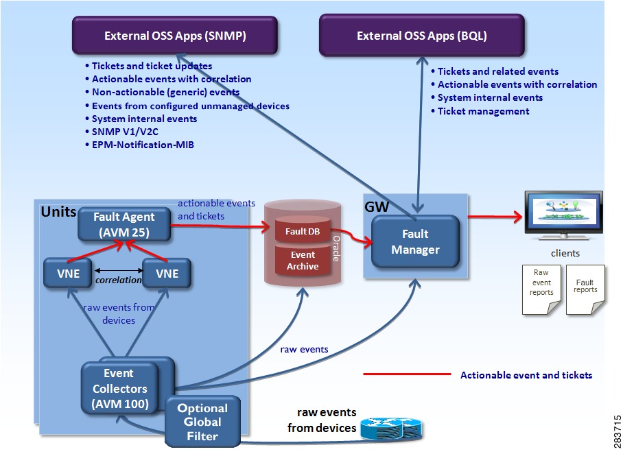
When a trap or syslog is sent from a device to Prime Network, it is received by the Event Collector, which runs on AVM 100. Figure 9-1 illustrates how Prime Network responds to incoming notifications from devices. The exact flow depends on how Prime Network is configured in your network.
Note
Figure 9-1 How Prime Network Responds to Incoming Notifications from Devices
Figure 9-1 also illustrates the two entities that store fault information, both of which reside in the Prime Network database:
•
You can only view information in the Event Archive using the reports mechanism. Event archiving is enabled by default, but you can disable it using the procedure in Disable Saving Raw Events to the Event Archive.
•
You can view information in the Fault Database using the Prime Network Events and Vision GUI clients.
The Event Archive and Fault Database data is archived and saved according to the settings in the Global Settings > Event Management Settings window in the Prime Network Administration GUI client. (See Events, Alarms, and Tickets.)
The following topics describe how the Event Collector, VNEs, and the Fault Agent (AVM 25) work together to process incoming notifications from devices. For more details about the event flow illustrated in Figure 9-1, see the Cisco Prime Network Integration Developer Guide.
Event Collector (AVM 100)
The Event Collector is the first receiver for incoming event notifications from devices. It is an internal service that is part of AVM 100. During installation, Event Collectors are created on the gateway and all units, but a single Event Collector AVM is started only on the gateway. By default, all new VNEs will register with the Event Collector on the gateway server. This Event Collector has the internal address 0.0.0.0 (this address is not related to the device IP address).
Note
When an event, trap, or syslog is received by the Event Collector, the Event Collector does the following:
1.
2.
3.
4.
5.
The Event Collector AVM requires a database connection when event archiving is enabled. If event archiving is disabled, a connection to the database is not required. To disable or reenable event archiving, see Disable Saving Raw Events to the Event Archive.
Event Collector and Unit Server High Availability
You can configure the Event Collector to run on a unit instead of the gateway. If the unit is also configured with unit server high availability, the Event Collector on the standby unit will drop all events because the Event Collector is disabled. This is by design; it should not start until a switchover occurs.
The standby unit contains a port watchdog script that listens for events on the unit's Syslog and SNMP ports. The script prevents unnecessary ICMP unreachable messages being sent back to the network. If a switchover occurs, the standby unit and Event Collector AVM will start, and the watchdog script releases the ports.
When the original unit comes back up, the standby Event Collector AVM goes back down, and the watchdog script recommences listening on the standby unit's Syslog and SNMP ports.
Note
•
•
No special configuration is required.
Prime Network also receives EPM-MIB traps from the network. By default Prime Network receives EPM-MIB traps from any source in the network. If desired, you can configure Prime Network to only process EPM-MIB traps arriving from a specific Prime Performance Manager server. The instructions for doing this are provided on the Cisco Developer Network at http://developer.cisco.com/web/prime-network/home.
VNEs
When a VNE receives an event from the Event Collector, the VNE does the following:
1.
Actionable events are events that the VNE can match with a predefined pattern. The VNE attempts to extract information from the raw event (the source, the problem, and the severity).
Non-actionable events are events that the VNE cannot match with a predefined pattern. These are also called generic events.
2.
3.
4.
For non-actionable events, the VNE takes no further action unless you have configured an Event Notification Service to forward the events to OSSs or e-mail recipients (see Configure Trap and E-Mail Notifications (Event Notification Service)).
5.
These actions are performed by a process within the VNE called the event manager, which is responsible for handling all network events, whether they are syslogs or traps, discovered during normal polling, or threshold-crossing alarms.
VNEs must be registered with an Event Collector's internal address (this address is not related to the device IP address). When a VNE is first initialized, the following occurs:
•
•
If the Event Collector receives a trap or syslog, and the trap or syslog's source IP address matches the VNE's management IP address, the Event Collector will forward the syslogs or trap to that VNE.
A VNE may have more than one IP address registered with the Event Collector, such as when a device is using other IP addresses as sources for syslogs or traps). These IP addresses can be discovered automatically from the device configuration but can also be manually configured using the VNE Event settings in Prime Network Administration (see VNE Properties: Events).
AVM 25 (Fault Agent)
When a VNE forwards an event to AVM 25, the Fault Agent does the following:
1.
2.
Event types are configured as ticketable in the registry. Prime Network will create a ticket for ticketable events, even if they are non-correlated events.
A trap or syslogs generates a ticket if:
–
–
Note
3.
AVM 25 requires a database connection to store information in the Fault Database so that it can be subsequently viewed in Prime Network Events. If a direct connection is not available, you can configure AVM 25 without connectivity to forward its events to another AVM 25 that does have a database connection. This is called using a proxy AVM 25. How to do so is described in Configuring Proxy AVM 25 for Units Not Connected to Database.
Keep these items in mind when starting and stopping AVM 25:
•
•
•
Example of Full Event Flow
The following steps show the flow of events when Device A sends a Port Down notification to the Event Collector.
1.
2.
3.
At this point, the Fault Database contains:
–
–
Users will be able to view the ticket in the GUI client.
When it queries the Fault Database, the Ticket Agent will pick up the Port Down event because it is correlated to a Link Down event, but not associated with any ticket. The Ticket Agent updates the Link Down service event, associates the Port Down event with the Link Down ticket, and updates the ticket information and severity aspect. At this point the Port Down event will be in the ticket's correlation information.
Configure the Event Collector to Listen for Incoming Events
Although Event Collector AVMs are created on the gateway and all units during installation, the gateway Event Collector AVM is the only one that is started. You can configure an Event Collector to run on a unit instead, or configure multiple Event Collectors. These topics describe the supported scenarios and best practices:
•
•
•
•
For an overview of how incoming events are handled, see How Prime Network Handles Incoming Events
Setting Up the Event Collector: Supported Scenarios
Note
The following guidelines can help you decide which Event Collector configuration is best for you:
•
•
•
Example: Single Event Collector on Gateway Server
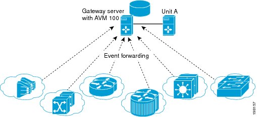
Figure 9-2 illustrates how events should be forwarded in a configuration where a single Event Collector is enabled on the gateway server.
Figure 9-2 Single Event Collector On Gateway Server
For this scenario, because the Event Collector AVM is enabled on the gateway server by default, all you must do is:
1.
2.
This scenario would also apply to a gateway configured with gateway local redundancy. If the backup gateway came online, it would use the same IP address as the original gateway, so it would continue to receive events sent from network elements.
You could also use this scenario where a gateway is configured with gateway geographic redundancy. However, if the backup (remote) gateway came online, it would have a different IP address from the local gateway. Therefore, you should configure network elements to also forward events to the remote gateway as part of Step 1.
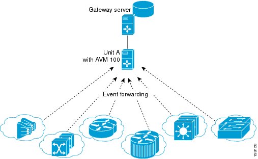
Example: Single Event Collector on Unit Server (No Unit High Availability)
Figure 9-3 illustrates how events should be forwarded in a configuration where one Event Collector is enabled on a unit server.
Figure 9-3 Single Event Collector On Unit Server
For this scenario, you must do the following:
1.
2.
3.
4.
No other configuration changes are required. New VNEs will automatically register to this Event Collector.
If the unit with the enabled Event Collector fails and is not operational, you must do the following:
1.
2.
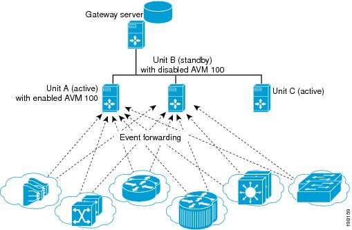
Example: Single Event Collector on Unit Server with Unit High Availability
Figure 9-4 illustrates how events should be forwarded in a configuration where one Event Collector is enabled on a unit server, and the unit server is part of a protection group that contains Unit A (an active unit with an enabled Event Collector), Unit B (standby unit with disabled Event Collector), and Unit C (active unit). See AVM 100 and Unit Server High Availability, for details about how the Event Collector operates in a unit server high availability scenario.
In Figure 9-4, devices are managed by Unit A.
Figure 9-4 Event Collector On Unit Server with Unit High Availability
For this scenario, you must do the following:
1.
2.
3.
4.
5.
If the unit with the enabled Event Collector fails, the Event Collector on the standby unit is automatically started and the VNEs are automatically reregistered with the Event Collector on the standby unit. See AVM 100 and Unit Server High Availability for information on what happens if the failed unit comes back up.
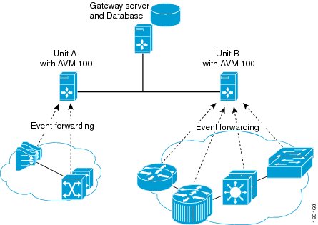
Example: Multiple Event Collectors on Unit Servers (No Unit High Availability)
Prime Network supports multiple enabled Event Collectors. The Event Collectors can be on the gateway and units, or just the units.
Figure 9-5 illustrates how events should be forwarded in a configuration with two Event Collectors enabled on different unit servers. This configuration is appropriate to a network in which devices have connectivity issues with the configured single Event Collector.
Deploying multiple Event Collectors does not increase the overall rate at which Prime Network parses, correlates, and saves information in the Fault Database. If Prime Network can parse and correlate 100 events per second, and you deploy two Event Collectors this number will not increase to 200.
Note
Figure 9-5 Event Collector On Two Unit Servers with No Unit High Availability
For this scenario, you must do the following:
1.
2.
3.
4.
5.
Enabling a Single Event Collector on a Gateway or a Unit
During installation, an Event Collector AVM is created on the gateway and all units, but it is started only on the gateway. By default, the enabled Event Collector has the internal address 0.0.0.0 (this address is not related to the device IP address). All new VNEs will register with the Event Collector on the gateway server.
Enabling the Event Collector on the Gateway Server
Although the Event Collector runs on the gateway by default, there may be instances where it has been stopped. If so and you need to restart it, use the following procedure.
Before You Begin
•
•
If no other Event Collector was enabled after the gateway Event Collector was stopped, do the following to restart the Event Collector:
Step 1
Step 2
If an Event Collector was enabled on another unit, do the following:
Note
Step 1
Step 2
Step 3
Step 4
Step 5
The Event Collector will begin processing events when they are received. By default, any new VNEs will register with the Event Collector on the gateway server.
Enabling a New Event Collector on a Unit
Follow this procedure to start a single Event Collector on a unit.
Note
Before You Begin
•
•
•
Note
To enable the Event Collector on a unit:
Step 1
# cd $ANAHOME/Main
# networkctl restart
Step 2
Step 3
By default, any new VNEs will register with the Event Collector on the unit.
Configuring and Enabling Multiple Event Collectors
Configuring a network to have two Event Collectors enabled on different unit servers is appropriate to a network in which devices have connectivity issues with the configured single Event Collector. However, deploying multiple Event Collectors does not increase the overall rate at which Prime Network parses, correlates, and saves information in the Fault Database. If Prime Network can parse and correlate 100 events per second, and you deploy two Event Collectors this number will not increase to 200.
An illustration of this configuration is provided in Example: Multiple Event Collectors on Unit Servers (No Unit High Availability).
Note
To configure multiple Event Collectors you must edit the registry using the runRegTool.sh script.
The runRegTool.sh script is in the directory NETWORKHOME/Main and uses the following format:
runRegTool.sh -gs 127.0.0.1 set unit-IP "avm100/agents/da/vne-key/trap/xidip" event-collector-address
The runRegTool.sh script accepts the following arguments:
How To Configure Multiple Event Collectors
Complete the following procedure for each additional Event Collector that needs to be configured. Because this is a completely new Event Collector, you do not have to stop or restart any AVMs.
Before You Begin
Configure the network elements to forward traps and syslogs to the appropriate Event Collector. If you are using unit server high availability, traps and syslogs should be forwarded to both the active and standby units.
To configure multiple Event Collectors:
Step 1
# cd $ANAHOME/Main
# ./runRegTool.sh -gs 127.0.0.1 set unit-IP "avm100/agents/trap/xidip" unit-IP
The update is automatically propagated from the gateway to the relevant units.
Step 2
Step 3
When you add new VNEs, you must register the VNEs to the appropriate Event Collector as described in Registering VNEs with a Non-Default Event Collector.
Example Procedure for Configuring Two Event Collectors on Two Units
This example illustrates how to configure an Event Collector to run on one unit, and a second Event Collector to run on a second unit. The configuration is as follows:
•
•
–
–
•
–
–
In this example, two Event Collectors are configured, one on each unit. Each Event Collector handles the events (SNMP traps and syslogs) sent from the network elements that correspond to the VNEs it manages.
After installing the gateway and the two units, configure the Event Collectors and the VNEs:
Step 1
# cd $ANAHOME/MainStep 2
# ./runRegTool.sh -gs 127.0.0.1 set 192.168.10.2 "avm100/agents/trap/xidip" 192.168.10.2
# ./runRegTool.sh -gs 127.0.0.1 set 192.168.10.3 "avm100/agents/trap/xidip" 192.168.10.3
Step 3
a.
# ./runRegTool.sh -gs 127.0.0.1 set 192.168.10.2 "avm200/agents/da/vne-key/trap/ip"
192.168.10.2
b.
# ./runRegTool.sh -gs 127.0.0.1 set 192.168.10.3 "avm300/agents/da/vne-key/trap/ip"
192.168.10.3
c.
Step 4
Registering VNEs with a Non-Default Event Collector
If you do not want a VNE to be registered with the default Event Collector—that is, the Event Collector that uses the internal address 0.0.0.0—you must manually change the VNE registration. (This internal address is not related to the device IP address.)
Note
Complete the following procedure to register VNEs to an enabled Event Collector:
Step 1
Step 2
Step 3
# cd $ANAHOME/MainStep 4
# ./runRegTool.sh -gs 127.0.0.1 set unit-IP "avmxxx/agents/da/vne-key/trap/xip" unit-IPThe update is automatically propagated to the relevant units. For details on the command syntax, see Example Procedure for Configuring Two Event Collectors on Two Units.
Step 5
Configuring Proxy AVM 25 for Units Not Connected to Database
If a unit server does not have a direct connection to the database, you can configure another unit to be its proxy and persist event information to the Fault Database. However, because there is no proxy support for the Event Collector (AVM 100), raw events will not be saved to the Event Archive. Therefore, you should disable raw event archiving as described in Disable Saving Raw Events to the Event Archive. If you do not disable event archiving, the log will contain errors because events are not being forwarded to VNEs nor are system events being generated.
To configure a proxy AVM 25, you must edit the registry (the avm25.xml file) for the unit that does not have database connectivity. The proxy unit will process the events as part of its normal event flow.
Step 1
Step 2
runRegTool.sh -gs 127.0.0.1 add unit-IP "avm25/services/management/proxy"
runRegTool.sh -gs 127.0.0.1 set unit-IP "avm25/services/management/proxy/IP" proxy-unit-IP
This runRegTool.sh scripts requires the following arguments:
The following is an example:
•
•
To configure Unit 1 to use Unit 2 as a proxy for AVM 25, enter these commands:
# cd $ANAHOME/Main
# ./runRegTool.sh -gs 127.0.0.1 add 192.168.10.2 "avm25/services/management/proxy"
# ./runRegTool.sh -gs 127.0.0.1 set 192.168.10.2 "avm25/services/management/proxy/IP"
192.162.11.1
Configure Trap and E-Mail Notifications (Event Notification Service)
Figure 9-1 illustrates how Prime Network processes incoming events. All events that are sent to the Fault Manager (which runs on the gateway) can be forwarded to external OSS applications using an Event Notification Service. Trap notifications can include additional information, such as an interface description or the business tag associated with an NE.
You can also use this service to configure e-mail notifications so that users are immediately informed about urgent events. A service can include network and non-network events, actionable and non-actionable events, and events from unmanaged devices. All events and tickets are normalized into the CISCO-EPM-NOTIFICATION-MIB trap format before they are forwarded. (Non-actionable events are events coming from unmanaged devices and events that the VNE cannot parse. These are also called generic events. See How Prime Network Handles Incoming Events, for more information.)
Note
This procedure explains how to create or edit an e-mail or trap notification service.
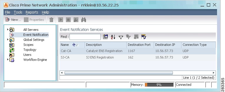
Step 1
Figure 9-6 Event Notification Service Window Listing Existing Services
From this window you can:
Step 2
a.
b.
c.
d.
Step 3
a.
b.
Exclude event types from the forwarded events
Filters the events or tickets out of the trap or e-mail notification. When you choose an event, Prime Network will also exclude:
•
•
Network Events
(Network and Non-Network Events only) Select the events to include in the filter. You can select events at these levels:
•
•
When you add events to the filter, Prime Network includes all clearing events
To specify event types for the filter:
1.
2.
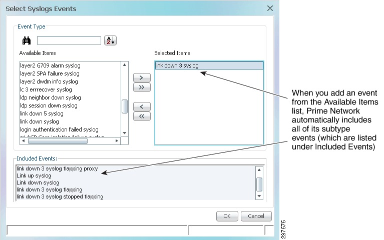
3.
If you do not choose specific events, Prime Network will forward all events of that type. Figure 9-7 shows that when you select the link 3 down syslog (under Selected Items), Prime Network automatically includes all of its subtype events (which are listed under Included Events).
To include generic traps, select Generic trap.
Non-Network Events
Figure 9-7 Example: Event Type and Subtypes
c.
Severity
Include tickets/events in the notifications if they are of the chosen severity.
.
d.
Step 4
a.
Note
–
–
–
b.
Step 5
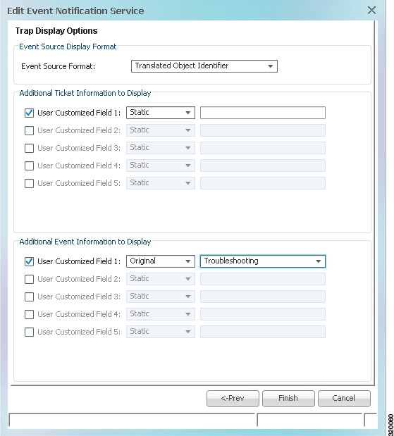
Figure 9-8 Display Options Page for Trap Notifications
a.
b.
For example, you could display the troubleshooting information for a ticket in the trap notification as shown in Figure 9-8:
–
–
Step 6
Configure System TCAs
To configure new threshold crossing alarms, use the Soft Properties feature. Soft Properties allows you to extend the supported properties for an NE, including monitoring selected properties and generating an alarm when these properties cross a user-defined threshold or violate a condition. Prime Network filters out irrelevant data, and sends only meaningful notifications.
For information on how to configure TCAs using Soft Properties, see Cisco Prime Network 3.10 Customization Guide.
Track Events
Prime Network provides a variety of preconfigured reports that can provide you with a wide range of event information. To run any of these reports, select Reports > Run Report > Events Reports and choose the report name.