-
Cisco Prime Network Administration Guide, 3.10
-
Preface
-
Set Up Prime Network and Its Components
-
Manage the Prime Network Software Image and Backups
-
Manage the Prime Network Components: Gateway, Units, AVMs, and VNEs
-
Manage Network Elements (VNEs)
-
Manage Redundancy for Units and Processes
-
Control Device Access Using Device Scopes
-
Manage User Accounts
-
Manage the Database and System Data
-
Control Event Monitoring
-
Manage Workflows and Activations
-
System Security
-
Perform Advanced VNE Configurations
-
Device Configuration Tasks for Proper Modeling
-
Prime Network Log Files
-
Manage the Prime Network Registry
-
VNE Properties Reference
-
Index
-
 Feedback
Table Of Contents
Perform Advanced VNE Configurations
CPU Utilization Problems: Where to Begin
Basic Procedures and Configurations: Reduced Polling
Advanced Configurations: Reduced Polling
Basic Configurations: Adaptive Polling
Advanced Configurations: Adaptive Polling
Regular Polling (VNE Polling Groups)
Smart Polling (On-Demand Polling)
Change Settings That Determine Device Reachability
VNE Management Communication Policies and How To Change Them
Change How Protocols are Tested for Reachability
Change How VNE Commands Are Executed (Collectors Command and Priorities)
What Are Collectors and Command Priorities?
Considerations for Using Fast Commands and Fast Collectors
Expedited Commands and Activation Scripts and Fast Collectors
Configuring a Command With the "Fast" Command Priority
Creating a Fast Collector for a VNE
Change Settings That Control VNE Data Saved After Restarts
Create Connections for Unmanaged Network Segments (Cloud VNEs and Links)
Unmanaged Segments and Cloud VNEs
Connecting the Cloud VNE to a Device
Creating and Deleting Static Links
Change VNE Telnet/SSH Login Rates (Staggering VNEs)
Registry Settings for VNE Discovery Timeout and Investigation State Reporting
Perform Advanced VNE Configurations
These topics provide advanced technical information about VNEs, including the configurable points:
•
Change Settings That Determine Device Reachability
•
•
•
Change VNE Polling Settings
Prime Network uses a variety of polling methods to monitor the network.Working together these mechanisms maintain the balance between ensuring model fidelity (more polling cycles) while protecting system performance (less polling cycles). Table 12-1 lists the polling methods used by Prime Network, their default behavior, and where you can find more information on each method.
Note
If you are experiencing high CPU usage, see CPU Utilization Problems: Where to Begin.
CPU Utilization Problems: Where to Begin
If you suspect ongoing CPU utilization problems, start with these troubleshooting steps:
1.
2.
3.
–
–
4.
–
5.
# ./runRegTool.sh -gs 127.0.0.1 set 0.0.0.0 "site/device-type/ipcore/software
versions/default version/amsi/topology/ethernet/MacTestEnable" false
For example, this command disables MAC-based topology for Cisco 7600 routers:
# ./runRegTool.sh -gs 127.0.0.1 set 0.0.0.0 "site/ciscorouter2/76xx/product/software
versions/default version/amsi/topology/ethernet/MacTestEnable" false
Reduced Polling
Note
All VNEs either use reduced polling or regular polling. When a VNE is using reduced polling, Prime Network will poll the device whenever it receives a configuration change event. Changes to the model are updated immediately. Reduced polling is the default polling method for new VNEs. If a device type does not support reduced polling, Prime Network uses regular polling.
Because the syslog facility is sometimes unreliable, the reduced polling mechanism has a fail-safe option. When this option is enabled, Prime Network polls the device's complete command history (from the archive log) to ensure that no device configuration changes were missed. This option is disabled by default (see Enable the Reduced Polling Fail-safe Option).
If you expect a device to receive multiple syslogs in a short period of time, you can enable a throttling mechanism which prevents the same command from being executed repeatedly. See Enable the Reduced Polling Throttling Mechanism.
If a VNE using reduced polling is moved to the Currently Unsynchronized state, it means it failed to identify one or more changes, or there is a gap in the configuration archive buffer. The device configuration archive buffer contains the configuration commands that were executed on the device. For Cisco IOS devices, it is possible for the buffer to overflow when a large number of commands are executed; thus some commands can be lost, a gap is identified, and the VNE is assumed to be out of synch with the device. VNEs using reduced polling are more sensitive to these changes due to their different polling frequency.
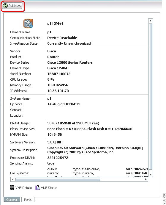
To quickly synchronize the VNE model without having to wait for the next polling cycle, click the Poll Now button in the VNE's inventory. Figure 12-1 provides an example.
Figure 12-1 Poll Now Button in Prime Network Vision
The information refresh is similar to the VNE discovery process, the main difference being what triggers the process.
Like any discovery process the VNE refresh has the potential of raising the CPU usage on the device. However, several factors work together to keep CPU usage low: the queueing mechanism that controls command execution, the VNE logic that reuses command results, and adaptive polling's throttle mechanism that introduces a delay between commands.
The amount of time needed for the VNE refresh depends on many factors, such as device and network latency, and gateway server activities. To help you understand when the refresh is in process and when it has completed:
•
•
Basic Procedures and Configurations: Reduced Polling
These topics provide procedures that will help you identify whether reduced polling is being used by a VNE, and how to change the setting:
•
•
•
•
Find Out Which Device Types Support Reduced Polling
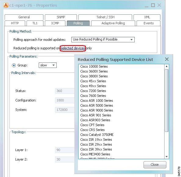
To find out whether or not a VNE supports reduced polling, check the listing in the VNE properties dialog as follows.
Step 1
Step 2
Step 3
Figure 12-2 Listing the Devices That Support Reduced Polling
Find Out Whether a VNE is Using Reduced Polling
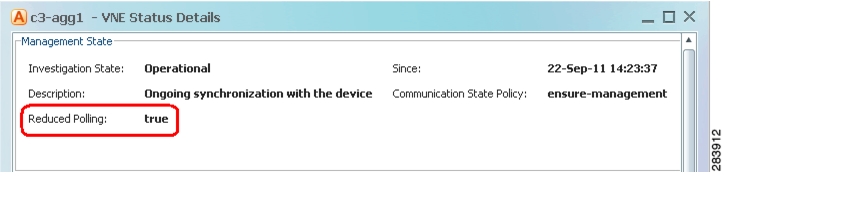
The VNE Status Details window displays a true/false setting for Reduced Polling that indicates whether the VNE is using reduced polling. If you were not sure that your device support reduced polling and you choose Use Reduced Polling if Possible as your polling method, this window is where you can find the result.
Step 1
Note
Step 2
Figure 12-3 Reduced Polling Setting in VNE Status Details Window
The value true means that the VNE is using reduced polling to monitor the device.
Turn Reduced Polling On or Off for a Single VNE
For reduced polling to work as designed, devices must be properly configured to generate device change events. See Device Configuration Tasks for Modeling.
Note
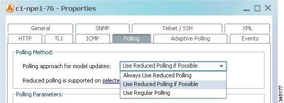
The VNE polling properties contains a drop-down list so you can choose a polling approach for the VNE. Table 12-2 lists the choices.
Table 12-2 Default Polling Approaches
Always use reduced polling
0
Prime Network will define the settings based on the recommended offset of model fidelity vs. interference. If the device type does not support event-based polling, Prime Network generates a Device Unsupported event.
Use this if you want to be notified that the device type does not support reduced polling.
You want the VNE to use reduced polling, but if the device type does not support it, you want to receive a notification (event).
Used reduced polling if possible
1
Prime Network will define the settings based on the recommended offset of model fidelity vs. interference. If the device type does not support event-based polling, Prime Network uses regular polling.
Note
You want the VNE to use reduced polling, but if the device type does not support it, you want the VNE to use regular polling.
Use regular polling
2
Instructs Prime Network to proactively poll configuration data using a configuration interval (usually every 15 minutes). This means that even in extreme circumstances where events are lost, the VNE would be synchronized after a maximum of 15 minutes (not 24 hours).
You want the VNE to use regular polling regardless of whether the device type supports reduced polling.
1 The registry enum is supplied in case you want to change the default polling method across the system.
To turn reduced polling on or off:
Step 1
Step 2
Step 3
a.
b.
Step 4
a.
b.
Figure 12-4 Reduce Polling Setting in VNE Properties Dialog Box
Step 5
Change the Default Polling Approach for All New VNEs
Reduced polling is enabled on all new VNEs by default. If a device does not support reduced polling, the polling method defaults to regular polling.
If you do not want reduced polling to be the default method, use this procedure to change the default across the Prime Network system. The change will take effort for all new VNEs.
Step 1
# cd $ANAHOME/MainStep 2
# ./runRegTool.sh -gs 127.0.0.1 get 127.0.0.1
avm11/services/plugin/BosManagePlugin/defaultSettings/defaultPollingMode
Prime Network will respond with an integer that maps to one of the following. The approaches are described in Table 12-2.
Always use reduced polling
Used reduced polling if possible (factory default)
Use regular polling
Step 3
# ./runRegTool.sh -gs 127.0.0.1 set 127.0.0.1
site/avm11/services/plugin/BosManagePlugin/defaultSettings/defaultPollingMode
polling-mode-enum
Step 4
Advanced Configurations: Reduced Polling
The preferred method for changing reduced polling settings is to use the GUI client, as described in Basic Procedures and Configurations: Reduced Polling. But some changes require an edit to the registry. That information is provided in the following topics.
Note
•
•
Enable the Reduced Polling Throttling Mechanism
For cases where a VNE using reduced polling receives multiple configuration change syslogs from the same device in a short time span, a throttling mechanism can be used to prevent the same command from being executed repeatedly. The throttle mechanism collects all change notifications that are received within a predefined interval, and when the interval expires, the VNE polls the device for updated information at one time. The throttle feature is turned off by default (the interval is set to 0). If a change is not immediately reflected in Prime Network Vision because the throttle is enabled, you can manually update the GUI using the Poll Now button (see Figure 12-1).
The interval should allow enough time for the change to be applied, including being applied to other affected devices. In the following example we change the interval to five minutes. This may not be a suitable interval in the following scenarios:
•
•
To check, enable, or disable the throttling mechanism for an individual VNE, use the following procedure.
Step 1
# cd $ANAHOME/MainStep 2
•
# ./runRegTool.sh -gs 127.0.0.1 get -entry unit-IP "avmxxx/agents/da/vne-key/evne
polling interval"
•
# ./runRegTool.sh -gs 127.0.0.1 set unit-IP "avmxxx/agents/da/vne-key/evne polling
interval" minutes
•
# ./runRegTool.sh -gs 127.0.0.1 unset unit-IP "avmxxx/agents/da/vne-key/evne polling
interval"
For example, this command would set the throttling interval to 5 minutes for a VNE named c7-npe1-76 on AVM 600, and would make the change to the Golden Source registry:
# ./runRegTool.sh -gs 127.0.0.1 set 127.0.0.1 "avm600/agents/da/c7-npe1-76/evne polling
interval" 5
Step 3
Enable the Reduced Polling Fail-safe Option
Because syslogs are not always reliable, the reduced polling mechanism provides a fail-safe option that polls the device's complete command history (from the archive log) to identify any new configuration commands that were missed. Prime Network will check the archive log according to the VNE's Configuration polling settings. If any syslogs were missed, Prime Network will poll the device and update its model.
If your inventory highly depends on events to update the model, you should enable this option for all devices.
Note
To enable the fail-safe option:
Step 1
Step 2
#./runRegTool.sh -gs 127.0.0.1 add 0.0.0.0 "site/cisco-router-repository/registry-path/instrumentation services/evne-interval"The variable registry-path depends on the device operating system:
Step 3
#./runRegTool.sh -gs 127.0.0.1 set 0.0.0.0 "site/cisco-router-repository/registry-path/instrumentation services/evne-interval" configurationStep 4
Adaptive Polling
Adaptive polling is a feature that preserves device integrity in extreme network scenarios or when encountering device caveats. When device CPU is exceedingly and consistently high, it introduces an interval between SNMP/CLI commands so that the device can quickly recover. In addition, some devices with exceptionally large configurations can generate very large Telnet responses—literally thousands of output lines. Because these are single, atomic commands, other techniques such as smooth polling cannot be applied.
If this occurs, the adaptive polling mechanism defines a limited terminal length, breaking the response into segments, inserts a delimiter (such as --More--), and does not resume until the VNE sends a space character. This technique is sometimes called flow control. During the pause, the network element can address other priorities. This ensures that the network element CPU utilization is not monopolized by Prime Network polling commands. Although the duration of these polling commands will be slightly longer, this is normally a desirable tradeoff.
The XML protocol also supports adaptive polling due to the fact that XML is a protocol that is handled over Telnet. Although adaptive polling is not formally supported over HTTP, because other (non-HTTP) protocols are involved in data collection, an overall improved result is also seen for HTTP.
Note
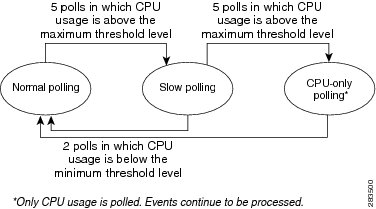
Figure 12-5 illustrates the adaptive polling mechanism with its default settings. You can adjust these settings as described in Configuring Adaptive Polling Settings for a VNE.
Figure 12-5 How Adaptive Polling Works
Note
The following steps provide more detail about the adaptive polling algorithm illustrated in Figure 12-5.
1.
Slow polling introduces a delay is added between sending the commands to the NE. (In SNMP, the delay is between SNMP packets sent to the device; in Telnet or SSH, the delay is between CLI commands sent to the device.) In addition, Telnet responses are divided into smaller parts, separated by a delimiter to adjust throughput.
2.
–
–
All polling is suspended except for CPU usage); however, syslogs and traps continue to be processed. The VNE is moved to the Currently Unsynchronized VNE investigation state.
3.
The average CPU usage is calculated using a CPU polling interval. The interval controls how often to poll the VNE for its CPU usage (for example, every 30 seconds). The interval is described in Table 12-4.
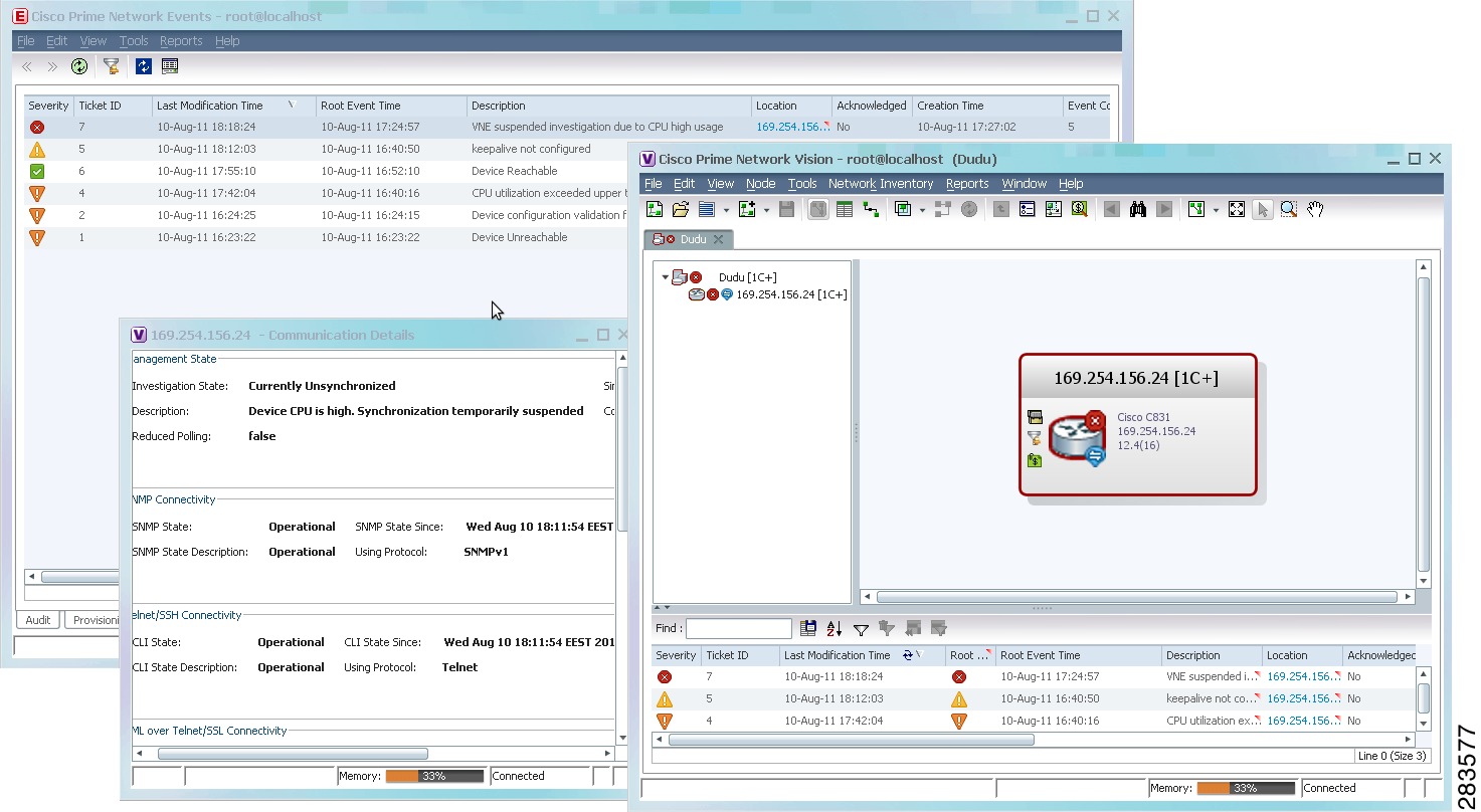
Figure 12-6 shows the an example of what you will see in Prime Network Events and Prime Network Vision when a VNE is experiencing high CPU usage. (The VNE Status Details window is launched from Prime Network Vision by clicking VNE Status from the device properties window.)
Figure 12-6 GUI Client Display for a VNE Experiencing High CPU Usage
If a VNE keeps moving from normal to slow polling to CPU-only polling, consider adjusting the thresholds that control adaptive polling. See Changing Adaptive Polling Thresholds and Delimiters.
Note
Basic Configurations: Adaptive Polling
These topics provide procedures that explain how to configure adaptive polling using the GUI, and how to turn off adaptive polling:
•
•
Configuring Adaptive Polling Settings for a VNE
The following procedure is the preferred method for configuring adaptive polling settings for a VNE. You can specify your settings in the VNE Properties dialog box.
Step 1
Step 2
If you are updating an existing VNE, select the VNE and right-click Properties.
Step 3
Step 4
Step 5
Table 12-3 Adaptive Polling Local Settings
Upper Threshold
Upper CPU usage threshold. When CPU usage exceeds this value for a specified number of (tolerance) polls, the adaptive polling mechanism is triggered and the VNE moves to slow polling or CPU-only polling.
90%
Lower Threshold
Lower CPU usage threshold. When CPU usage drops below this value for a specified number of polls (2 by default), the VNE reverts from slow polling to normal polling and related alarms are cleared.
60%
Upper Tolerance
Number of high-CPU polls required to move the VNE to slow polling. When the Upper Threshold is crossed this number of consecutive CPU polls, the VNE moves from normal polling to slow polling. (To be more conservative, enter a lower number.)
For example, using the default settings, a Cisco IOS-XR VNE would move from normal polling to slow polling after 5 minutes — that is, 5 Upper Tolerance polls with a 60-second interval (see Table 12-4).
5
Lower Tolerance
Number of low-CPU polls required to revert the VNE to normal polling. When CPU utilization falls below the Lower Threshold for this number of consecutive polls, the VNE reverts from slow polling or CPU-only polling to normal polling. (To be more conservative, enter a higher number.)
2
Maintenance Tolerance
Total number of high-CPU polls required to move the VNE to CPU-only polling. This number includes the Upper Tolerance polls.
For example, an Upper Tolerance of 5 and a Maintenance Tolerance of 10 means:
•
•
Using the default settings, this means that Cisco IOS-XR VNEs, which have a 60-second polling interval, would move from normal polling to CPU-only polling in 10 minutes:
•
•
See Table 12-4 for the default interval settings.
10
SNMP Delay
Delay (in milliseconds) between SNMP commands that are sent from the VNE to the device.
500
Telnet Delay
Delay (in milliseconds) between Telnet commands that are sent from the VNE to the device.
500
Step 6
If you are creating a new VNE, click OK to create the new VNE, or continue with the VNE configuration.
Turning Off Adaptive Polling for a VNE
Step 1
Step 2
Step 3
Step 4
Advanced Configurations: Adaptive Polling
The following advanced procedures explain how to change polling intervals and other adaptive polling delimiters, such as the delays that are introduced between commands:
•
•
Note
Changing the CPU Usage Polling Interval
The command for retrieving CPU utilization data is sent to the device according to the interval setting in Table 12-4. Therefore, if Prime Network reports a high CPU utilization on a VNE, it means that for last 5 CPU polls, the average CPU utilization has been crossing the recommended threshold.
For example, the CPU usage information for some devices is gathered using the following command (other devices may use SNMP):
show processes cpu | include CPU utilization
Table 12-4 lists the parameters that control how often the data is polled. Complete directory paths to the registry entries are provided in the procedure that follows the table.
Example for Cisco IOS XR Devices
As shown in Table 12-4, Prime Network provides a cpu-util-counter-bucket variable to calculate average CPU usage for Cisco IOS XR devices. The following table provides examples of values you might see for the same interval setting, but with different cpu-util-counter-bucket settings.
With a cpu-util-bucket-counter setting of 5, the adaptive polling mechanism would recognize average CPU usage on the device to be 16%.
Use the following procedure to adjust how often CPU utilization is polled by a specific VNE.
Note
Step 1
# cd $ANAHOME/MainStep 2
•
# ./runRegTool.sh -gs 127.0.0.1 set unit-IP "avmxxx/agents/da/vne-key/dcs
/registrations/com.sheer.metrocentral.coretech.common.dc.ManagedElement/cpu
usage/instrumentation services/interval" 60000
•
# ./runRegTool.sh -gs 127.0.0.1 set unit-IP "avmxxx/agents/da/vne-key/dcs
/registrations/com.sheer.metrocentral.coretech.common.dc.ManagedElement/cpu
usage/instrumentation services/interval" 30000
Step 3
# ./runRegTool.sh -gs 127.0.0.1 set 127.0.0.1 "avmxxx/agents/da/vne-key/dcs
/registrations/com.sheer.metrocentral.coretech.common.dc.ManagedElement/cpu
usage/instrumentation services/command/parsing params/cpu-util-counter-bucket" 15
Step 4
Changing Adaptive Polling Thresholds and Delimiters
Table 12-5 describes the registry parameters (and default values) for adaptive polling for Cisco VNEs.
The following procedure explains how to check these settings on a VNE, and how to adjust a VNE so that adaptive polling problems are handled more conservatively.
Note
Step 1
# cd $ANAHOME/MainStep 2
# ./runRegTool.sh -gs 127.0.0.1 get unit-IP
"avmxxx/agents/da/vne-key/dcs/type/com.sheer.metrocentral.coretech.common.dc.ManagedElemen
t/AdaptivePolling/registry-entry"
For example, to check the maintenance_tolerance setting for VNE c7-sw7 on AVM 600 on the gateway server:
# ./runRegTool.sh -gs 127.0.0.1 get 127.0.0.1 "avm600/agents/da/c7-sw7/dcs/type/com.sheer.metrocentral.coretech.common.dc.ManagedElement /AdaptivePolling/maintenance_tolerance"10Step 3
•
# ./runRegTool.sh -gs 127.0.0.1 set 127.0.0.1
"avm600/agents/da/c7-sw7/dcs/type/com.sheer.metrocentral.coretech.common.dc.ManagedEle
ment/AdaptivePolling/upper_tolerance" 3
•
# ./runRegTool.sh -gs 127.0.0.1 set 127.0.0.1
"avm600/agents/da/c7-sw7/dcs/type/com.sheer.metrocentral.coretech.common.dc.ManagedEle
ment/AdaptivePolling/lower_tolerance" 5
Step 4
Regular Polling (VNE Polling Groups)
Prime Network VNEs poll the network element in a repetitive fashion according to a predefined time interval, called a polling cycle. The Polling Groups window enables you to manage these cycles by specifying the intervals you want, creating a group with those intervals, and then assigning VNEs to use that polling group.
Prime Network comes with two predefined polling groups named default and slow. You can employ these or, alternatively, define a new polling group, apply configured polling intervals to the group, and assign the polling group to managed elements. The VNE will poll the network element according to the preset values. This ensures polling of devices for different information consistently and in accordance with technical and business requirements.
Note
Alternatively, you can create a new polling group to fine-tune the frequency at which information is retrieved from the managed elements, thus controlling the amount of network traffic used by the various VNEs. For example, these are cases where a polling group with a longer polling interval would be useful:
•
•
Table 12-6 identifies the settings for the default and slow polling groups.
Configure a VNE To Use Regular Polling
By default, all VNEs using reduced polling. To change a VNE to use regular polling, use this procedure. If you want all new VNEs to use regular polling, you must edit the registry setting as described in Change the Default Polling Approach for All New VNEs.
Step 1
Step 2
Step 3
Figure 12-7 Reduce Polling Setting in VNE Properties Dialog Box
Step 4
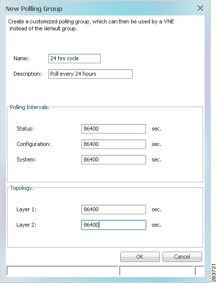
How to Create a New Polling Group
In the following example, a new polling group is created that polls for all device information every 24 hours. The polling group is then applied to a new VNE.
Step 1
Step 2
Step 3
Figure 12-8 Creating a Polling Group Called 24 Hrs Cycle
The following table describes the fields in this dialog box.
Step 4
Step 5
Step 6
Step 7
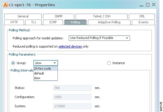
Apply the 24 hrs cycle polling group to the VNE by clicking the Polling tab and selecting 24 hrs cycle from the Polling Parameters Group dropdown list, as shown in Figure 12-9.
Figure 12-9 Applying the 24 Hrs Cycle Polling Group to a VNE
Step 8
Smooth Polling
Each VNE uses device registrations (commands) to collect different kinds of data from the associated network element. Each registration specifies the commands required to obtain a specific given item of data, and can be configured with a specific polling interval or logically associated with one of the polling intervals on a per device/VNE basis.
The smooth polling mechanism that takes commands in the same polling cycle, and spreads their execution throughout the polling cycle. Rather than using a timer-based approach (where a large number of commands will be potentially scheduled for execution at the same time), the smooth polling method generates a random number (within the polling interval) for the next execution. This ensures that the commands get executed at least once within the required period, while also reducing the probability that two or more commands will run at the same time. This "smooths out" the load of the management protocols on the network and reduces their impact. Obviously, the longer the polling interval, the more effective smooth polling can be.
Note that smooth polling augments regular polling only after the completion of the first poll. Smooth polling is enabled in Prime Network by default.
How to Enable or Disable Smooth Polling
While it is rare that you will need to change the smooth polling setting, you can disable it if a VNE's polling intervals are extremely small.
Note
Step 1
# cd $ANAHOME/MainStep 2
•
Note
# ./runRegTool.sh -gs 127.0.0.1 set unit-IP
"avmxxx/agents/da/vne-key/smoothpollingenabled" false
•
# ./runRegTool.sh -gs 127.0.0.1 unset unit-IP
"avmxxx/agents/da/vne-key/smoothpollingenabled"
Step 3
Smart Polling (On-Demand Polling)
When Prime Network receives an incoming notification about a model change, the event provides information about the change but not about other components that may be affected by the change. For this reason Prime Network polls for this information that can affect the VNE model.
Sometimes queries are repeatedly submitted to a device. Common cases for this are when a user opens a Prime Network Path Tracer, window, and when an expedited event is received by Prime Network. To prevent overpolling, the smart polling mechanism uses a polling protection interval that specifies the minimum amount of time that must pass before a query can be sent to a device a second time.
For example, if multiple GUI or BQL users are concurrently using Prime Network Path Tracer, if the paths being viewed have common network elements, the details are collected according to the smart polling interval, and the data is shared without performing duplicate polls.
This example shows how Prime Network uses smart polling when receiving multiple instances of an expedited event:
1.
2.
If the interval was 10 seconds, and the second instance of Query A arrived 7 seconds after the first instance of Query A, the second query would be dropped.
For expedited queries, Prime Network will queue the query to run when the interval is complete. Using the previous example, suppose the first instance of the query arrived at 12:00:00. The second instance arrives at 12:00:07. Because the query is expedited, the second query is queued to run at 12:00:10 (10 seconds after the first query).
If you change the smart polling interval, keep the following in mind:
•
•
Therefore, the interval value should be based on the amount of time required for the network to stabilize after a change.
Note
Step 1
# cd $ANAHOME/MainStep 2
# ./runRegTool.sh -gs 127.0.0.1 set 0.0.0.0
"site/instrumentordefaults/baseCommand/polling-protection-interval" value
Step 3
# networkctl restart
Change Settings That Determine Device Reachability
Prime Network VNEs communicate with network devices using a variety of protocols, and traps and syslogs. To determine the reachability of specific protocols, Prime Network runs multiple connectivity tests to check the device reachability.
The status of all of these protocols determine whether a device is reachable. By default, Prime Network marks a device as unreachable only when all enabled protocols are down; that is, the protocols are not responding, and the device is not generating syslogs or traps. However, you can change this behavior to fit your network.
These topics describe how reachability is determined and how you can change this behavior to fit the needs of your network:
•
•
VNE Management Communication Policies and How To Change Them
The management communication policy determines when Prime Network changes a VNE communication state to Device Unreachable or Device Partially Reachable. The policies allow you to decide how more or less strictly you want to track protocol health. Figure 4-12 illustrates how you can find out which management communication policy is being used by a VNE. Table 12-7 describes the supported policies.
Note
By default, Prime Network uses the ensure-management policy. You can check the policy that is being used with the following command:
# cd $ANAHOME/Main
# ./runRegTool.sh -gs 127.0.0.1 get 127.0.0.1
"site/agentdefaults/da/dcs/type/com.sheer.metrocentral.coretech.common.dc.ManagedElement/R
eachability/policy"
ensure-management
#
If you want to change to a different management communication policy, see the instructions in Change How Protocols are Tested for Reachability.
Changing the Management Communication Policy and Policy
The following procedure explains how to configure Prime Network to use a different policy to determine device reachability.
Note
Use runRegTool.sh to make your registry changes, using the following format:
runRegTool.sh -gs 127.0.0.1 set 0.0.0.0 "site/agentdefaults/da/type/com.sheer.metrocentral.coretech.common.dc.ManagedElement/Reachability/policy" value
The following table describes the policy key.
Table 12-8 Registry Setting for Reachability Policies
policy
Management communication policy Prime Network should use. Supported values are strict, ensure-management, or notstrict. For information on the policies, see VNE Management Communication Policies and How To Change Them.
ensure-
management
Note
Step 1
# cd $ANAHOME/MainStep 2
# ./runRegTool.sh -gs 127.0.0.1 set 0.0.0.0
"site/agentdefaults/da/dcs/type/com.sheer.metrocentral.coretech.common.dc.ManagedElement/R
eachability/policy" strict
Step 3
# cd $ANAHOME/Main
# networkctl restart
Protocol Reachability Tests
These topics describes the tests Prime Network conducts to check the health of the SNMP, Telnet, XML, ICMP, and HTTP protocols. Settings for all of the protocols are listed in Table 12-9. You can check Prime Network Vision to get details about the health of each protocol (see Figure 4-12).
SNMP
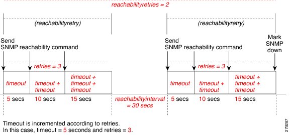
SNMP connectivity is determined by the IP address of the device. The VNE polls the sysObjectId.0 (which is assumed to be available, simple, and immediate) and waits for a response (such as ".1.3.6.1.2.1.1.2.0"). The registry entries that control SNMP reachability testing are provided in Table 12-9.
The following steps describe how Prime Network checks the health of the SNMP protocol.
How these values work together is illustrated in Figure 12-10.
Figure 12-10 SNMP Reachability Testing
By default, lazyreachability is disabled. This means the default reachability algorithm is proactive—the VNE sends an SNMP request to the device and expects a response. If a response is not received within a certain amount of time, the SNMP protocol is marked as Down. However, if the lazyreachability registry key is enabled, the VNE will not be proactive. Instead, the VNE will wait until a regular query is sent to the device, and if no result is received, the VNE marks the protocol as Down.
Telnet and XML
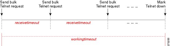
Telnet connectivity is determined by the IP address of the device. The VNE sends a space and carriage return and waits for the device to echo the prompt. The registry entries that control Telnet reachability testing are provided in Table 12-9.
Note
The following describes the two most common scenario for Telnet problems.
Figure 12-11 illustrates Scenario 2, where a device is not returning timely responses to a bulk command.
Figure 12-11 Telnet Reachability Testing When Bulk Command Not Completed
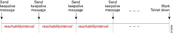
Sometimes it is not necessary for the VNE to maintain an open Telnet connection to a device, even if the session is idle. This is illustrated in Figure 12-12:
a.
b.
Figure 12-12 Reachability Testing to Retain Telnet Connection
Finally, if an open Telnet session is idle for an amount of time that exceeds idletime, Prime Network closes the connection. If the protocol connection is dropped, it is possible that reachability problems may go undetected by Prime Network until the Telnet connection is needed.
By default, lazyreachability is disabled. This means the default reachability algorithm is proactive—the VNE sends a Telnet request to the device (and a space and a newline character) and expects a response. If a response is not received within a certain amount of time, the Telnet protocol is marked as Down. If the lazyreachability registry key is enabled, the VNE will not be proactive. Instead, the VNE will wait until a regular query is sent to the device, and if no result is received, the VNE marks the protocol as Down.
ICMP
ICMP connectivity is determined by sending a ping to a device and waiting for a reply. The registry entries that control ICMP reachability testing are provided in Table 12-9. Due to a system limitation, ICMP packets cannot be sent. ICMP connectivity is therefore determined by attempting to establish a TCP connection on port 7 (Echo).
1.
2.
3.
HTTP
HTTP connectivity is determined by trying to log into the device. If the device does not respond within timeout, the device is marked as Down.
Change How Protocols are Tested for Reachability
Table 12-9 lists the registry settings that control how Prime Network tests the SNMP, Telnet, XML, ICMP, and HTTP protocols to ensure reachability. These tests are described in Protocol Reachability Tests.
Note
Note
Change How VNE Commands Are Executed (Collectors Command and Priorities)
The following topics provide a high-level description of how VNE collectors execute the commands required to build a model of a device, and how to adjust the way Prime Network executes these commands:
•
•
•
•
•
What Are Collectors and Command Priorities?
Prime Network discovers and models a network element using commands that are called registrations. Registrations are forwarded to a VNE's collectors, which are the VNE components that communicate with the physical network element. By default, each VNE is configured to have two collectors: an SNMP collector and a Telnet collector. These collectors can execute only one command at a time. Because many commands are sent to the network element during modeling, each collector maintains a queue of commands. When a collector is busy, any new incoming commands are placed at the end of the queue (FIFO, or first in, first out). When a collector finishes with one command, it executes the next command in the queue in a serial fashion.
In most cases, executing command in a serial fashion is adequate. However, it may not be efficient enough for network elements with large configurations, for the following reasons:
•
•
Note
Command Priorities and Command Queues: Normal and Fast
To prevent delays in command execution, Prime Network uses a command priority mechanism. Every command is given one of the following priorities:
•
•
To deal with the two priorities, each collector maintains two queues: a fast queue for the fast commands and a normal queue for the normal commands. When a collector is available it will execute commands in the fast queue first. It will not execute any commands in the normal queue until the fast queue is empty.
Fast Collectors
Even a fast priority command can suffer a delay if, when it is sent, the collector is already busy executing a very large normal priority command.
For this situation, you can configure an additional collector called a fast collector. The fast collector is a special collector that is dedicated to commands in the fast queue. When the fast queue is empty, the fast collector is dormant.
For example, if you configure a fast collector for the Telnet protocol, Prime Network will have:
•
•
Collectors and Thread Sharing
To decrease the overall number of threads used at the VNE layer, each AVM maintains pools of threads that are shared by the VNEs. VNEs acquire and release the threads as needed, in an asynchronous fashion.
One thread pool is dedicated to activation scripts. This thread pool grows dynamically, up to the number of VNEs in the AVM. Each thread is destroyed after 60 seconds of inactivity. Even if you expect a large number of activation scripts to run in parallel, you should see no IO degradation. However, we recommend that you do not run more than 100 concurrent activation scripts on a unit.
Considerations for Using Fast Commands and Fast Collectors
There are obvious benefits of marking commands with a fast priority, and configuring and additional fast collector. But these methods also have some cost and possible risks.
Risks of Using the Fast Command Priority
Only a small number of registration commands should have a fast command priority. If too many commands are marked as fast, the queue for the fast commands can become long, with the following results:
•
•
Risks of Using Fast Collectors
We recommend that you do not configure an additional fast collector for the following reasons:
•
•
General Recommendation for Fast Commands and Fast Collectors
For commands that are high priority, mark the command with the fast command priority. Do not configure an additional fast collector unless the command takes an unusually long time to execute.
Expedited Commands and Activation Scripts and Fast Collectors
By default, all expedited commands, activation scripts, and CPU monitoring commands have a fast command priority.
CPU monitoring commands have a fast command priority so that Prime Network can quickly identify and respond to high CPU issues that may affect the device and overall system.
Expedited commands have a fast command priority, but only for their first execution. Normally, expedited command execute with little delay. When it has successfully executed, the expedited command returns to a normal command priority. You should only consider using an additional fast collector if expedited commands are consistently delayed by other commands that require a long time to execute. To find out which commands are expedited, see the specific syslog, trap, and command descriptions in:
•
•
•
Activation scripts (which are converted into commands) have a fast command priority by default. However, activation scripts must adhere to a more strict timeout mechanism than expedited commands.
All commands—expedited commands or commands in activation scripts—have a timeout period which begins when command execution starts. But activation scripts have an additional timeout on the gateway. This gateway timeout begins when the commands are sent to the VNE. If a collector is occupied for an extended period, the gateway timeout may expire and the activation will fail.
If activation commands are timing out, consider the following approaches:
•
•
General Recommendation for Using Fast Collectors with Expedited Commands and Activation Scripts
The default behavior (described earlier) should be sufficient for both activation scripts and expedited commands. Consider an additional fast collector only if commands are experiencing unacceptable delays.
Note
Configuring a Command With the "Fast" Command Priority
By default, all commands have a normal command priority and are executed by the collector in a FIFO basis. You can mark a command to have the fast (high) command priority, which means it will be placed in the collector's fast queue rather than its normal queue. Use the following procedure to edit the command priority in the registry.
Note
Before You Begin
•
•
Note
To set a command priority to fast, use the following procedure.
Step 1
# cd $ANAHOME/MainStep 2
# ./runRegTool.sh -gs 127.0.0.1 set 0.0.0.0 "site/registry-path/cpu usage
snmp/instrumentationservices/command/priority" fast
Step 3
# networkctl restart
Creating a Fast Collector for a VNE
By default, every protocol has only one collector (that is, no fast collector). You can configure a fast Telnet or SNMP collector for a VNE by editing the registry.
Note
Note
Before You Begin
•
•
To create a fast Telnet or SNMP collector for a specific VNE, use the following procedure.
Step 1
# cd $ANAHOME/MainStep 2
If the VNE is on the gateway server, unit-IP should be 127.0.0.1.
If the VNE is on a unit server, unit-IP should be the unit's IP address.•
# ./runRegTool.sh -gs 127.0.0.1 set unit-IP
"avmxxx/agents/da/vne-key/ips/vne-ip/protocols/snmp/maxfastcollector" 1
•
# ./runRegTool.sh -gs 127.0.0.1 set unit-IP "avmxxx/agents/da/vne-key/ips/vne-ip/protocols/telnet/maxfastcollector" 1
Step 3
Note
Change Settings That Control VNE Data Saved After Restarts
Persistency is the ability to store information in the unit for later use. These topics describe the VNE persistency mechanism in Prime Network:
Note
Persistency Overview
Persistency information is stored across unit, AVM, and VNE restarts. This accelerates the startup time after restarts because Prime Network does not have to re-poll the complete NE.
VNE data persists during runtime when a VNE polls data from a device, and the VNE updates the files in the file system for changes in the device's response according to the persistency variables. When a VNE is started or restarted, the persistency information is read from these files once. Every normal polling or refresh that takes place after the first time will read the data from the device itself and not from the files.
VNE data persistency is lost in the following scenarios (but alarm persistency is saved):
•
•
•
The upgrade mechanism automatically clears all persistency files on Prime Network gateways and units. This option does not clear the alarm history that is stored in the Prime Network database.
Instrumentation Persistency
Instrumentation persistency is used mainly to:
•
•
•
For more information, see Instrumentation Persistency.
Topology Persistency
Topology persistency creates topology between devices on startup when the VNE is loaded, instead of performing the entire discovery process. Verification of the links is then performed. For more information, see Topology Persistency.
Alarm Persistency
Alarm persistency saves information about the VNE components that send alarms. When a VNE sends an alarm, the VNE can save this information (that it has sent an alarm of type X). This information can then be used by the VNE components after restarts to verify whether the VNE needs to send clearing alarms where changes have occurred in the device when the VNE was down. For more information, see Alarm Persistency.
Alarm Persistency
Alarm persistency enables the system to clear alarms that relate to events that occurred while the system was down. For example, a Link Down alarm is generated, and then the system goes down. While the system is down, a Link Up event occurs in the network, but because the system is down, it does not monitor the network. When the system goes up, the alarm is cleared because the system remembers that a Link Down alarm exists, and the system needs to clear it by sending a corresponding alarm.
Persisting events are held in the AlarmPersistencyManager. Each VNE contains an AlarmPersistencyManager object. Alarms are added to and removed from the AlarmPersistencyManager object in order to maintain the status of an event, whether it exists in the repository or not; that is, whether an up alarm or a clearing alarm has been generated. Two copies of alarm persistency information are maintained: one in the memory, and the other on disk.
At startup, the AlarmPersistencyManager retrieves the events persisted for the containing VNE. Because alarm persistency is based on a VNE's IP address, if you change the IP
Event data in the files is updated at the following times:
•
•
•
Initialization
Alarm persistency is controlled by settings in the registry. Global alarm persistency information is stored in agentdefaults.xml. The major settings are listed in Table 12-10. The settings for these configurable items only apply when trying to retrieve data from the persistency files. Individual event persistency information is described in Configuring Alarm Persistency for a Specific Event.
Note
Retrieving Events
At startup, each VNE calls its AlarmPersistencyManager to load the persisting events.
If the file does not exist or is corrupt, no events are loaded. Faulty event objects are not loaded. Events which have been in the file for longer than the configured maximum age are not loaded. No age tests are held during ordinary runtime.
Storing Events
At shutdown, events are saved to the VNE's event persistency file as a precaution in case the events have not already been saved.
Removing an Event
An event is searched for and removed using the same information which was used to add it. The event is removed from memory because a clearing event (for example, a Link Up alarm) has been generated, and the persistency information is no longer required. After the removal, the AlarmPersistencyManager stores the events after a writing delay, as specified in the registry.
Removing an Event and Clearing an Alarm
The AlarmPersistencyManager is able to search for and remove an event, and send a clearing alarm for the event, if it is found that this information is no longer required because the alarm has been cleared.
After an event has been added to or removed from the AlarmPersistencyManager, a delayed message is sent to the AlarmPersistencyManager. Upon its arrival, the message triggers the events to be stored to the file.
Configuring Alarm Persistency for a Specific Event
Alarm persistency can be configured per event using the setting described in Table 12-11. Event-specific persistency information is stored in event-persistency-application.xml.
Note
Table 12-11 Registry Setting for Alarm Persistency for a Specific Event
alarm-persistency
Enable persistency for a specific event.
In the following LDP Neighbor Loss alarm, the LDP Neighbor Down event marks the alarm as present in the system (persisted), and the LDP Neighbor up event is used to clear the alarm from persistency (unpersist):
<key name="LDP neighbor loss"><entry name="default">event-persistency-application/templates/generic persistency event</entry><key name="sub-types"><key name="LDP neighbor down"><entry name="alarm-persistency">persist</entry></key><key name="LDP neighbor up"><entry name="alarm-persistency">unpersist</entry></key></key></key>Alarm Persistency Default Configuration
The following alarms are configured to be persistent.
Instrumentation Persistency
The instrumentation layer persists the information that was collected from the device to the file system. When the VNE restarts, it uses this information to emulate the device's response, and thus the VNE can be modeled according to its last persistent state. The next polling instance is performed against the real device.
The registry entries that control instrumentation persistency are provided in Table 12-13.
Note
Topology Persistency
Prime Network supports persistency for Layer 1 topological connections. Layer 1 topology supports one connection per Device Component (DC), so the physical topology reflects a single port connected by a single link.
The following topologies are persisted:
•
•
Static topology, which identifies physical links configured by the user, is persisted once a user configures the static link between the two entities. This link is then stored in the registry, in the AVM key that contains the specific VNE registrations.
For other topologies, every time a link is created, the persistency mechanism writes the link to this file. When a link is disconnected, the file representing the link is removed.
Note
Topology persistency is controlled by the setting listed in Table 12-14.
Note
Table 12-14 Registry Setting for Topology Persistency
persistency
Enable physical topology persistency.
Note
true
Create Connections for Unmanaged Network Segments (Cloud VNEs and Links)
Cloud VNEs represent unmanaged network segments that are connected to two or more managed segments. This prevents interruptions to alarm correlations and affected subscribers for the managed segments.
These topics describe how to add and remove links between two ports of two network elements in the network that are connected to some unmanaged network segment through a Cloud VNE. Dynamic links are used to connect these ports to a cloud.
Static links override any existing autodiscovered topology in the system. A static link is identical in all respects to a link that is autodiscovered.
•
•
Note
Unmanaged Segments and Cloud VNEs
Three types of technology simulations are supported for Cloud VNEs: Frame Relay, ATM, and Ethernet. If you want to work with Cloud VNEs with Ethernet support, see Ethernet on Cloud VNEs.
Administrators can create Cloud VNEs that represent:
•
•
•
All VNEs can also be configured to connect dynamically to a Cloud VNE. When loading, the VNE gathers whatever data is relevant to the Cloud VNE, and sends the data to it. Upon receiving this information, the Cloud VNE builds the corresponding model to allow the topology to connect the two VNEs.
To create a Cloud VNE, you must do the following:
1.
2.
Note
Ethernet on Cloud VNEs
When using an Ethernet LAN cloud to represent unmanaged network segments, be aware of the following:
•
•
•
•
•
•
•
•
•
•
Note
Configuring Duplicate IP Addresses on Ethernet Interfaces
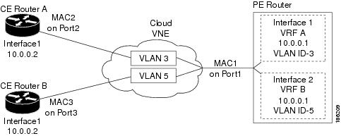
Figure 12-13 provides an example of a configuration of duplicate IP addresses on Ethernet interfaces that are connected to the same Cloud VNE.
Figure 12-13 Duplicate IP Addresses on Ethernet Interfaces
In Figure 12-13, a PE router and two CEs are connected to an unmanaged Ethernet access network, represented by a Cloud VNE.
The PE router is connected to the Cloud VNE through Port1. Two interfaces configured on Port1 are connected to different VRFs (VRF A and VRF B). Both VRF interfaces are configured with the same IP address (10.0.0.1). Each interface is configured with a different VLAN encapsulation (VLAN-ID 3 and VLAN-ID 5), and is connected to a different VLAN in the unmanaged network (VLAN 3 and VLAN 5).
The two CEs are connected to different VLANs in the unmanaged network: CE A is connected to VLAN 3 through Port2, and CE B is connected to VLAN 5 through Port3. Both Port2 and Port3 are access ports (that is, untagged ports with no VLAN encapsulation) and are configured with identical IP addresses (10.0.0.2).
The Cloud VNE creates a similar port for each port connected to it, and two bridges, one per VLAN (that is, a bridge for VLAN 3 and a bridge for VLAN 5). Each bridge contains a forwarding table with the MAC addresses of the ports connected to that VLAN. In this example, the bridge representing VLAN 3 contains MAC1 and MAC2, and the bridge representing VLAN 5 contains MAC1 and MAC3.
Connecting the Cloud VNE to a Device
Each Cloud VNE has a unique agent ID (that is used as the Cloud VNE's identifier) that cannot be used to access any network element. To connect a regular VNE to a Cloud VNE, the VNE must be configured with the physical port that should be connected, and the agent ID of the Cloud VNE.
When configuring a Cloud VNE for dynamic operation, the cloud model and the topology (that is, the link between the Cloud VNE and the adjacent VNE) are discovered and managed automatically by Prime Network.
To configure the Cloud VNE to operate dynamically, after creating a new Cloud VNE, you must:
1.
2.
3.
Before You Begin
If you are creating an Cloud VNE with Ethernet support, read Ethernet on Cloud VNEs.
Step 1
a.
The following is an example of an optimized GET command for VNE PE_South:
<command name="Get"><param name="oid"><value>{[ManagedElement(Key=PE_South)][PhysicalRoot]}</value></param><param name="rs"><value><key name="imo-view-controller"><entry name="depth">10</entry><entry name="register">true</entry><entry name="cachedResultAcceptable">false</entry><key name="requiredProperties"><key name="com.sheer.imo.IPhysicalRoot"><entry name="EquipmentHolders"/></key><key name="com.sheer.imo.IEquipmentHolder"><entry name="ContainedEquipmentHolder"/><entry name="ContainedEquipment"/></key><key name="com.sheer.imo.IEquipment"><entry name="SupportedPTPs"/></key><key name="com.sheer.imo.IPhysicalTerminationPoint"><entry name="ContainedCurrentCTPs"/></key></key><key name="requiredAspects"></key></key></value></param></command>b.
<?xml version="1.0" encoding="UTF-8"?><IPhysicalRoot><ID type="Oid">{[ManagedElement(Key=PE_South)][PhysicalRoot]}</ID><EquipmentHolders type="IMObjects_Array"><IChassis><ID type="Oid">{[ManagedElement(Key=PE_South)][PhysicalRoot][Chassis]}</ID><ContainedEquipmentHolder type="IMObjects_Array">....<IEquipmentHolder><ID type="Oid">{[ManagedElement(Key=PE_South)][PhysicalRoot][Chassis][Slot(SlotNum=1)]}</I D><ContainedEquipment type="IModule"><ID type="Oid">{[ManagedElement(Key=PE_South)][PhysicalRoot][Chassis][Slot(SlotNum=1)][Mod ule]}</ID><SupportedPTPs type="IMObjects_Array"><IPortConnector><ID type="Oid">{[ManagedElement(Key=PE_South)][PhysicalRoot][Chassis][Slot(SlotNum=1)][Mod ule][Port(PortNumber=FastEthernet1/1)]}</ID><ContainedCurrentCTPs type="IMObjects_Array"><IPhysicalLayer><ID type="Oid">{[ManagedElement(Key=PE_South)][PhysicalRoot][Chassis][Slot(SlotNum=1)][Mod ule][Port(PortNumber=FastEthernet1/1)][PhysicalLayer]}</ID></IPhysicalLayer></ContainedCurrentCTPs></IPortConnector><IPortConnector><ID type="Oid">{[ManagedElement(Key=PE_South)][PhysicalRoot][Chassis][Slot(SlotNum=1)][Mod ule][Port(PortNumber=FastEthernet1/0)]}</ID><ContainedCurrentCTPs type="IMObjects_Array"><IPhysicalLayer><ID type="Oid">{[ManagedElement(Key=PE_South)][PhysicalRoot][Chassis][Slot(SlotNum=1)][Mod ule][Port(PortNumber=FastEthernet1/0)][PhysicalLayer]}</ID></IPhysicalLayer></ContainedCurrentCTPs></IPortConnector></SupportedPTPs></ContainedEquipment></IEquipmentHolder>....</ContainedEquipmentHolder></IChassis></EquipmentHolders></IPhysicalRoot>The OID is {[ManagedElement(Key=PE_South)][PhysicalRoot][Chassis][Slot(SlotNum=1)][Module][Port(PortNumber=FastEthernet1/0)][PhysicalLayer]}
c.
For example, the OID from the preceding step should be changed to:
{[ManagedElement(Key=PE_South)][PhysicalRoot][Chassis][Slot(SlotNum=1)][Module][Port(PortNumber=FastEthernet1\!slash\!0)][PhysicalLayer]}
Step 2
a.
b.
# cd $ANAHOME/Mainc.
cat registry/avmcloudAvmId.xml
In the following example, a cloud was defined on AVM 358:
# cat registry/avm358.xml<?xml version="1.0" encoding="UTF-8"?><key name="avm358"><entry name="default">mcvm</entry><entry name="avmkey">AVM 358</entry><key name="agents"><key name="da"><key name="Cloud"><entry name="default">sheer/cloud/product/software versions/default version</entry><entry name="element type">SHEER_NETWORKS_CLOUD</entry><entry name="deletePersistency">true</entry><entry name="adaptivePollingType">1</entry><key name="creationTime"><entry name="time">1311516933201</entry></key><key name="pollingrates"><entry name="default">pollinggroups/default</entry></key><key name="amsi"><key name="topology"><key name="dynamic"><key name="permissible-subnet"><entry name="subnet">0.0.0.0/0</entry></key></key><key name="static"></key></key></key><key name="maintenance"><entry name="activated">false</entry></key><key name="ips"><entry name="agentId">784</entry><key name="Cloud">...d.
# ./runRegTool.sh -gs 127.0.0.1 add unit-IP
"avmxxx/agents/da/vne-key/dcs/instance/physical-layer-oid/cloud topology"
# ./runRegTool.sh -gs 127.0.0.1 set unit-IP
"avmxxx/agents/da/vne-key/dcs/instance/physical-layer-oid/cloud topology/id"
cloud-agent-ID
The following lists the parameters you must define:
unit-IP
The IP address of the Solaris machine on which the parent AVM resides (for the VNE that will connect to the Cloud VNE). If the AVM is on the gateway server, unit-IP should be 127.0.0.1.
avmxxx
The ID of the parent AVM (for the VNE that will connect to the Cloud VNE).
vne-key
The name of the VNE which will connect to the Cloud VNE.
physical-layer-oid
The OID of the VNE port which will connect to the Cloud VNE. This is the OID you identified in Step 1 of this procedure.
cloud-agent-ID
The agent ID of the Cloud VNE. (This is the Cloud VNE you created in Add a New Device Type.)
Example:
# ./runRegTool.sh -gs 127.0.0.1 add 192.168.100.1
"avm900/agents/da/PE_South/dcs/instance/{[ManagedElement(Key=PE_South)][PhysicalRoot][
Chassis][Slot(SlotNum=1)][Module][Port(PortNumber=FastEthernet1\!slash\!0)][PhysicalLa
yer]}/cloud topology"
# ./runRegTool.sh -gs 127.0.0.1 set 192.168.100.1 "avm900/agents/da/PE_South/dcs/instance/{[ManagedElement(Key=PE_South)][PhysicalRoot][ Chassis][Slot(SlotNum=1)][Module][Port(PortNumber=FastEthernet1\!slash\!0)][PhysicalLa yer]}/cloud topology/id" 784The previous example connects a VNE named PE_South (which resides in avm900 on unit 192.168.100.1) with a Cloud VNE that has the agent ID 784. The connection with the Cloud VNE is made using the physical layer of PE_South that has the OID:
{[ManagedElement(Key=PE_South)][PhysicalRoot][Chassis][Slot(SlotNum=1)][Module][Port(PortNumber=FastEthernet1/0)][PhysicalLayer]} is connected to the Cloud VNE with the agent ID 784.
e.
Step 3
Note
For each Cloud VNE, do the following:
a.
b.
# cd $ANAHOME/Mainc.
# ./runRegTool.sh -gs 127.0.0.1 add unit-IP
"avmxxx/agents/da/cloud-vne-key/amsi/topology/dynamic/permissible-subnet"
# ./runRegTool.sh -gs 127.0.0.1 set unit-IP
"avmxxx/agents/da/cloud-vne-key/amsi/topology/dynamic/permissible-subnet/subnet"
permissible-subnet
The following lists the parameters you must define:
Note
subnet-2,subnet-3, and so on).Example:
# ./runRegTool.sh -gs 127.0.0.1 add 192.168.100.1
"avm900/agents/da/EthernetCloud/amsi/topology/dynamic/permissible-subnet"
# ./runRegTool.sh -gs 127.0.0.1 set 192.168.100.1
"avm900/agents/da/EthernetCloud/amsi/topology/dynamic/permissible-subnet/subnet"
0.0.0.0/0
The previous example configures the permissible subnet 0.0.0.0/0 (meaning all IPv4 subnet connections are allowed), on a Cloud VNE named EthernetCloud (which resides in avm900 on unit 192.168.100.1). To allow all IPv6 subnet connections, use subnet 0::0/0.
d.
Creating and Deleting Static Links
Note
You can create a static link between devices by selecting the two end ports from the device physical inventory in Prime Network Administration. To create a static topological link, you need to supply the exact location of the two end ports (at both ends of the link). The physical hierarchy in which the port is located defines the location of a port, as follows:
Device > [shelf] > module > [submodule] > port
Links are bidrectional, and needs to be added only once.
Note
The new link is validated after the two ports are selected, but before the link is added. Validation checks:
•
•
•
•
•
For links between LAGs (IEEE 802.3ad), Prime Network also validates the following:
•
•
If validation reveals that one of the ends is part of a static link, you are asked to delete the previous link manually. If validation reveals that one of the ends is part of a dynamic link, the previous link is overridden.
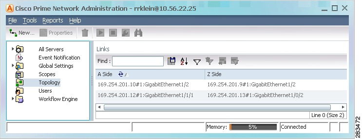
Figure 12-14 provides an example of the Topology window.
Figure 12-14 Topology Window
The Topology window displays all static links defined in the system, including the A side and Z side of the link.
To create a new static link:
Step 1
Note
The A Side and Z Side lists enable you to choose the devices and the ports for the static link. When you select a device from the list, the physical inventory of the device is displayed the dialog box.
Step 2
To delete a static link, right-click the link in the Topology window and choose Delete.
Change VNE Telnet/SSH Login Rates (Staggering VNEs)
The VNE staggering mechanism controls the rate at which VNEs initiate Telnet/SSH connections across a network managed by Prime Network. This prevents degraded performance on TACACS servers, which can result when there are many concurrent connections.
The mechanism is implemented across the following Prime Network components:
•
•
•
When the gateway receives a Telnet authorization request, it queues the requests in a FIFO (first in, first out) manner. If the gateway denies the request, the VNE communication state is changed to Device Partially Managed and a System event is generated (discovery can be prolonged if the VNE is not granted permission). In addition, the VNE Status Details window is updated to say the gateway denied the service. The VNE will continue to request the login, and once a connection is permitted, the VNE communication state changes accordingly and a clearing System event is generated.
Enabling the VNE Staggering Mechanism
This service is disabled by default; in other words, all VNEs are allowed to initiate login sequences. To enable it, use the following procedure:
Step 1
# cd $ANAHOME/MainStep 2
a.
# ./runRegTool.sh -gs 127.0.0.1 set 0.0.0.0
site/mcvm/services/agentbootstrap/VLAA/enable true
b.
# ./runRegTool.sh -gs 127.0.0.1 set 0.0.0.0
site/agentdefaults/da/ip_default/protocols/telnet/authorizedlogin true
c.
Step 3
a.
–
# ./runRegTool.sh -gs 127.0.0.1 set 0.0.0.0
avm99/services/vneLoginSupervisor/allowedConcurrentLoginsNum logins
We recommend an initial concurrent login setting of 1000:
# ./runRegTool.sh -gs 127.0.0.1 set 0.0.0.0
avm99/services/vneLoginSupervisor/allowedConcurrentLoginsNum 1000
–
# ./runRegTool.sh -gs 127.0.0.1 set 0.0.0.0
avm99/services/vneLoginSupervisor/vneFinishedLoginTimeout milliseconds
We recommend an initial setting of 5000 milliseconds (5 seconds):
# ./runRegTool.sh -gs 127.0.0.1 set 0.0.0.0
avm99/services/vneLoginSupervisor/vneFinishedLoginTimeout 5000
b.
# ./runRegTool.sh -gs 127.0.0.1 set 0.0.0.0
avm99/services/initlevel5/vneLoginSupervisor
com.sheer.system.os.services.vne.login.VneLoginSupervisorServiceImpl
c.
# runall.csh networkctl -avm 99 restart
Disabling the VNE Staggering Mechanism
To disable it, use the following procedure:
Step 1
# cd $ANAHOME/MainStep 2
a.
# ./runRegTool.sh -gs 127.0.0.1 set 0.0.0.0
site/mcvm/services/agentbootstrap/VLAA/enable false
b.
# ./runRegTool.sh -gs 127.0.0.1 set 0.0.0.0
site/agentdefaults/da/ip_default/protocols/telnet/authorizedlogin false
c.
Step 3
a.
# ./runRegTool.sh -gs 127.0.0.1 unset 0.0.0.0
avm99/services/initlevel5/vneLoginSupervisor
com.sheer.system.os.services.vne.login.VneLoginSupervisorServiceImpl
b.
# runall.csh networkctl -avm 99 restart
Registry Settings for VNE Discovery Timeout and Investigation State Reporting
Table 12-15 lists registry settings you can change to control the following discovery and state reporting behaviors:
•
•
•
Note
Track VNE-Related Events
When you audit VNE behavior, you are checking the backend process that models and monitors a device in the network. The following table provides ways you can get historical information on VNE-related events. You can tailor your search or reports by specifying keywords (such as VNE).