-
Cisco IP Solution Center Infrastructure Reference, 4.0
-
Index
-
About This Guide
-
Getting Started
-
WatchDog Commands
-
Service Inventory > Inventory and Connection Manager
-
Service Inventory > Inventory and Connection Manager > Inventory Manager
-
Service Inventory > Device Console
-
Service Design
-
Monitoring
-
Administration
-
Cisco CNS IE2100 Appliances
-
Property Settings
-
Glossary
-
 Feedback
Table Of Contents
Getting Started
This chapter provides information about how to get started to use Cisco IP Solution Center (ISC) and gives a structural overview of this manual. The information is in the following categories:
System Recommendations
The system recommendations and requirements are listed in Chapter 1, "System Recommendations" of Cisco IP Solution Center Installation Guide, 4.0. The recommendation is to thoroughly review this list before even planning your installation, to be sure that you have all the hardware and software you must successfully install.
CautionThere is no identified and supported way to upgrade from ISC 3.0 to ISC 4.0. To upgrade from ISC 3.0 to ISC 4.0, you must contact ISC Marketing, e-mail: isc-mktg@cisco.com.
Introduction
Cisco IP Solution Center, 4.0 (ISC 4.0) is a follow-on release to Cisco IP Solution Center, 3.2 (ISC 3.2), with the exceptions listed in Cisco IP Solution Center Release Notes, 4.0.
This manual lists many features that are common among all the applications, which are sold and licensed separately. The applications and their respective User Guides reference this document for setup steps necessary before creating a policy and then a service request specific to the application.
The Full Menus Graphical User Interface (GUI), is separated into the following large sections (tabs):
•
•
•
•
The remaining sections in this chapter explain the sections and subsections of this manual that explain the functionality available from these tabs.
Structural Overview
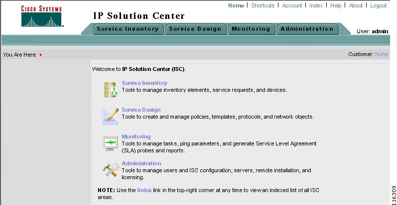
After you log into Cisco IP Solution Center (ISC), the first window to appear is the Home window, as shown in Figure 1-1, "Home Window."
Figure 1-1 Home Window
Note
This overview includes the following sections:
Product Category Tabs
The organization of this manual is based on the tabs shown in Figure 1-1, "Home Window." Click either the specific tab or the name in the data pane:
•
•
•
•
Links
In the upper right-hand corner of the Home window (Figure 1-1), additional links appear that function as follows:
•
•
On the far right of the You are Here: line on the Home window (Figure 1-1), is the name of a Customer Context, which is explained in the "Customer" section.
Home
When you click Home, you always return to the first window to appear, as shown in Figure 1-1, "Home Window."
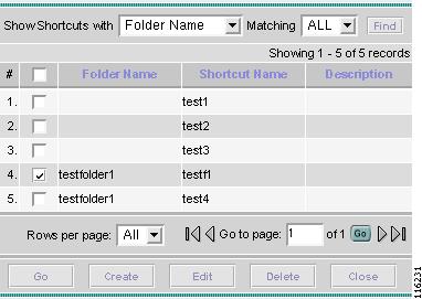
Shortcuts
When you click Shortcuts, you can define shortcuts to help quickly navigate to day to day operations. In addition, by grouping these shortcuts together into folders, you can create work flows specific to your operating environment. Shortcuts are further explained in the following steps:
Step 1
Figure 1-2 ISC Shortcuts
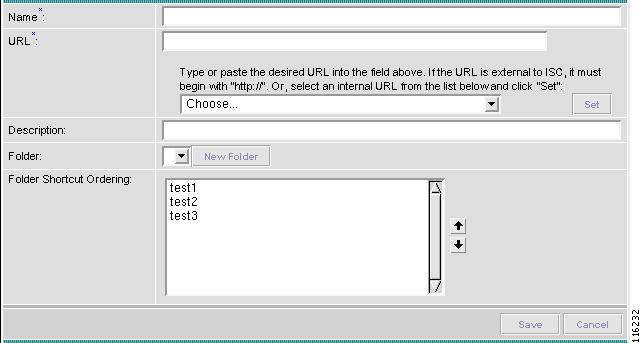
Step 2
Figure 1-3 New ISC Shortcut
Step 3
Step 4
Step 5
Account
When you click Account, you can change your password without the SysAdmin or UserAdmin privileges. This allows you to edit the user profile, including changing the password.
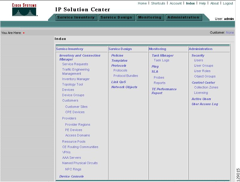
Index
When you click Index, you receive an overall picture of all choices from which you can click and jump to, as shown in Figure 1-4, "Index of all Choices."
Figure 1-4 Index of all Choices
Help
When you click Help, you receive a pointer to the documentation set once it is on CCO.
About
When you click About, you receive the product name and version.
Logout
When you click Logout, you log out of the product.
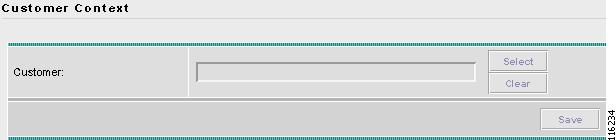
Customer
On the far right of the You are Here line of the Home page is Customer: followed by None (default) or a customer name. This is referred to as Customer Context. The advantage of Customer Context is to focus only on information for a specified customer. Set the Customer Context, as follows:
Step 1
Figure 1-5 Customer Context
Step 2
Step 3
Step 4
Step 5
Step 6
Common GUI Components
GUI components that are common on many windows are as follows:
Filters
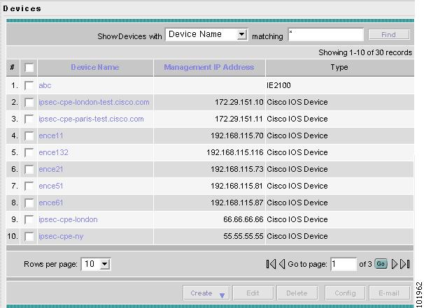
At the top of many windows you can filter information that appears in the window. As shown in Figure 1-6, "Example of Filtering, Rows per Page, and Changing Pages," you can click the drop-down menu for categories, then in the matching field enter the search criteria, using * if you wish to indicate anything will be a match (you can enter only * or you can place * before other characters, in the middle of other characters, at the end of other characters, or in multiple locations), and click Find. In some cases you might also have a field after the matching field from which you can select or enter more specifics for your Find.
Rows per Page
In the bottom left corner of many windows, as shown in Figure 1-6, "Example of Filtering, Rows per Page, and Changing Pages," you can change the number of rows shown on this window in Rows per page. Click the drop-down menu and you can select 5, 10, 20, 30, 40, or All.
Note
Go To Page
In the bottom right corner of many windows, as shown in Figure 1-6, "Example of Filtering, Rows per Page, and Changing Pages," there is Go to page field of y. In the field, you can enter the page to which you want to navigate and then click the Go button to get there. The y indicates the last page for this topic. Another way to navigate to a specific page is to use the arrows. You can click the > arrow to navigate to the next page or the furthest arrow to the right >| to navigate to the last page. You can click the < arrow to navigate to the previous page or the furthest arrow to the left |< to navigate to the first page.
Figure 1-6 Example of Filtering, Rows per Page, and Changing Pages
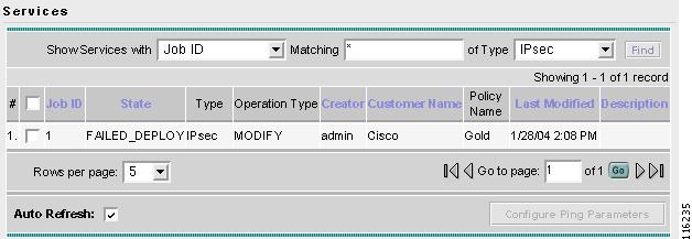
Auto Refresh
At the bottom left corner of several windows, there is a check box used to enable or disable the Auto Refresh feature, as shown in Figure 1-7, "Example of Auto Refresh." Checking this box causes the screen and its data to refresh every n milliseconds. The amount of time between refresh cycles can be set in the DCPL property: GUI.srRefreshRate. By default, the Auto Refresh feature is enabled to 30000 milliseconds.
Figure 1-7 Example of Auto Refresh
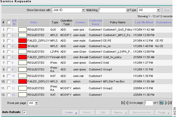
Color Coding
In the Service Request table, the Task table, and the Device table, the colors you see indicate the state of the items, as shown in Figure 1-8, "Colors as Identifiers."
In the Service Request table, the states have the following colors:
•
•
•
•
•
•
•
•
•
•
•
In the Task table, the states have the following colors:
•
•
•
•
•
•
In the devices table, the states have the following colors:
•
•
•
Figure 1-8 Colors as Identifiers
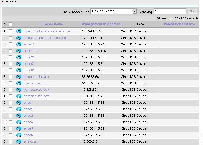
Icons
In some windows with tables of information, icons appear to show the type of device, as shown in Figure 1-9, "Devices—Icons."
Note
Figure 1-9 Devices—Icons
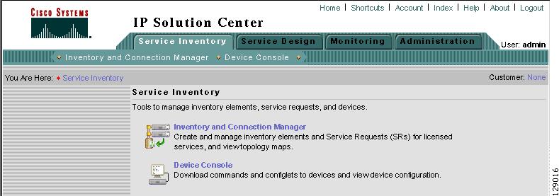
Service Inventory
Service Inventory contains tools to manage inventory elements, service requests, and devices. This is explained in "Service Inventory > Inventory and Connection Manager," and "Service Inventory > Device Console."
From the Home window you receive upon logging in, click the Service Inventory tab and you receive a window as shown in Figure 1-10, "Service Inventory Selections."
Figure 1-10 Service Inventory Selections
The selections are as follows:
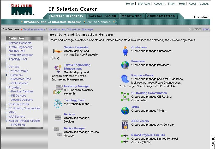
•
The functions within Inventory and Connection Manager are shown in Figure 1-11, "Inventory and Connection Manager Selections," and are as follows:
–
–
–
–
–
–
–
–
–
–
–
–
–
Figure 1-11 Inventory and Connection Manager Selections
•
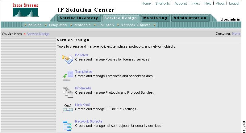
Service Design
Service Design contains management tools for creating and managing policies, templates, protocols - NOT SUPPORTED in this release. -, Link QoS, and service attributes. This is explained in Chapter 6, "Service Design."
From the Home window you receive upon logging in, click the Service Design tab and you receive a window as shown in Figure 1-12, "Service Design Selections."
Figure 1-12 Service Design Selections
The selections are as follows:
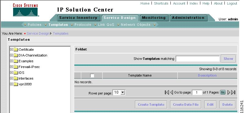
•
•
Figure 1-13 Templates Selections
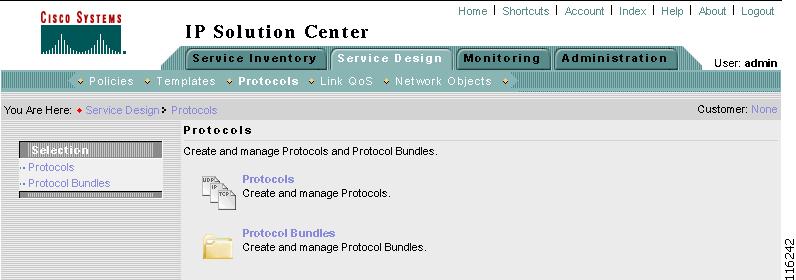
•
–
–
Figure 1-14 Protocols Selections
•
•
Monitoring
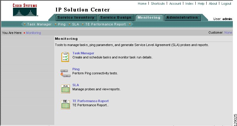
Monitoring contains tools to manage tasks, ping parameters, and Service Level Agreement (SLA) probes and reports. This is explained in "Monitoring."
From the Home window you receive upon logging in, click the Monitoring tab and you receive a window as shown in Figure 1-15, "Monitoring Selections."
Figure 1-15 Monitoring Selections
The selections are as follows:
•
•
•
•
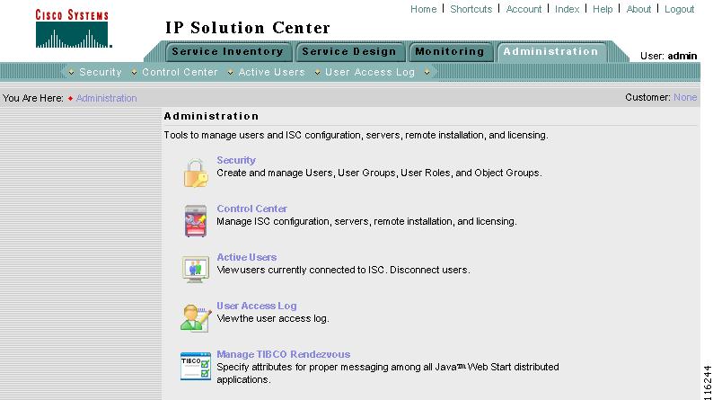
Administration
Administration contains tools to manage users, ISC configuration, servers, remote installation, and licensing, to view users and the user access log, and to specify attributes for some messages. This is explained in detail in "Administration."
From the Home window you receive upon logging in, click the Administration tab and you receive a window as shown in Figure 1-16, "Administration Selections."
Figure 1-16 Administration Selections
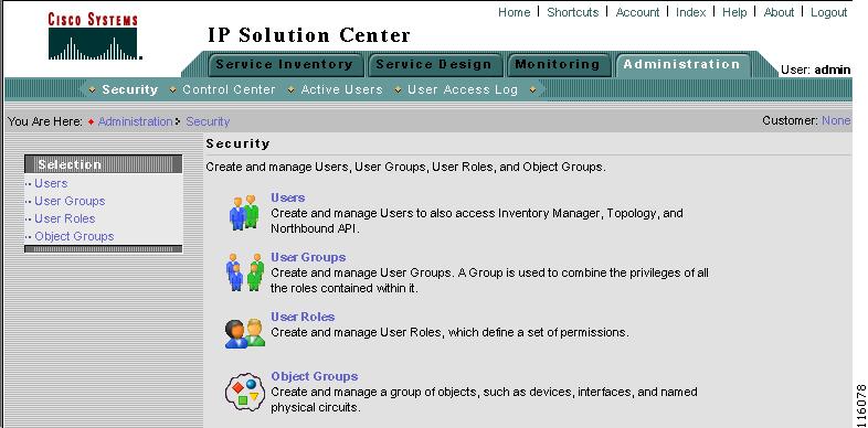
The selections are as follows:
•
–
–
–
–
Figure 1-17 Security Selections
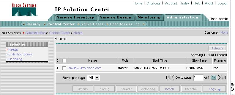
•
–
Note
–
–
Figure 1-18 Control Center Selections
•
•
•