-
Cisco IP Solution Center Infrastructure Reference, 4.0
-
Index
-
About This Guide
-
Getting Started
-
WatchDog Commands
-
Service Inventory > Inventory and Connection Manager
-
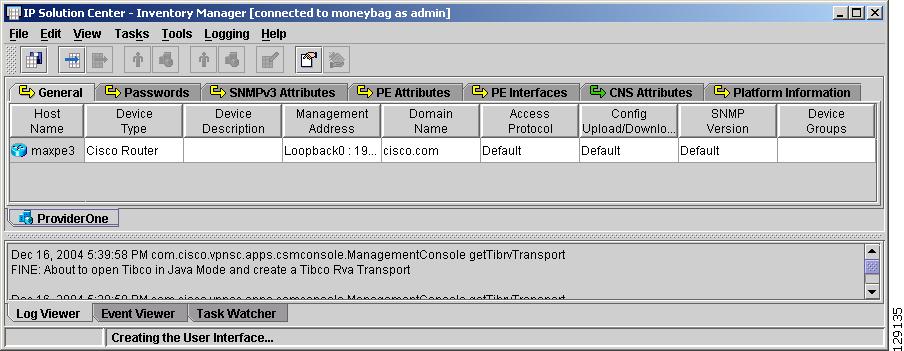
Service Inventory > Inventory and Connection Manager > Inventory Manager
-
Service Inventory > Device Console
-
Service Design
-
Monitoring
-
Administration
-
Cisco CNS IE2100 Appliances
-
Property Settings
-
Glossary
-
 Feedback
Table Of Contents
Service Inventory > Inventory and Connection Manager > Inventory Manager
Inventory Manager from End to End
Importing Devices from Configuration Files
Importing Devices with Auto Discovery
Configuring Device Credentials and SNMP Parameters
Collecting Configuration Files
Marking Interfaces for IPsec, Firewall, NAT, or QoS
Creating a New Customer with Devices
Creating a New Provider with Devices
Importing Connections with NPC Auto Discovery
Importing Services with Service Discovery
Introducing the Inventory Manager GUI
Inventory Manager GUI Reference
Load Default Values to Selected Cells
Apply Interface Marking Rules to Selection
Show Color Coded Column Headers
Collect Latest Configuration Files
UNIX Command Line Interface (UNIX CLI)
MPLS Service Discovery Overview
MPLS Service Discovery Process
Ring Topology Discovery (Connection Discovery)
Service Inventory > Inventory and Connection Manager > Inventory Manager
This chapter describes how to use Inventory Manager to prepare service inventory for the IP Solution Center (ISC) provisioning process. It contains the following subsections:
•
Overview of Inventory Manager
•
•
•
•
•
Overview of Inventory Manager
Inventory Manager provides a method of managing mass changes to inventory and service model data in the ISC provisioning process. In this process, Inventory Manager enables an operator to import network specific data into the ISC Repository (Repository) in bulk mode.
Inventory Manager performs three primary functions:
•
•
Note
•
Auto Discovery is an important tool in this process and is invoked from Inventory Manager. It can also be invoked from a Unix command line interface although this method is not recommended (see UNIX Command Line Interface (UNIX CLI)). For a detailed description of Auto Discovery, see Auto Discovery.
Prerequisites and Limitations
This document is intended for network engineers who have sufficient experience with MPLS VPN, L2VPN, and IPsec to provision these technologies using ISC.
Note
All of the network elements that you plan to provision should support the required hardware features and Cisco IOS versions.
Client Requirements
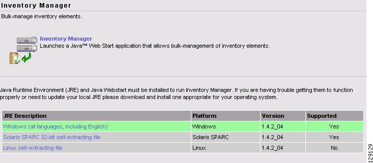
Java Runtime Environment (JRE) and Java Web Start must be installed to run Inventory Manager. If you are having trouble getting them to function properly, or need to update your local JRE, you can download and install the version appropriate for your operating system:
•
•
•
Name Resolution
Inventory Manager requires name resolution. The ISC HTTP server host must be in the Domain Name System (DNS) that the web client is using or the name and address of the ISC server must be in the client host file.
SNMP
Prior to device discovery, SNMP must be enabled. All devices in the ISC provisioning environment must support SNMP. ISC supports SNMP versions 1, 2c, and 3.
CDP
CDP must be enabled to discover devices. Inventory Manager uses CDP to perform the service discovery task. CDP should be enabled globally and at the interface level for each device in the ISC provisioning environment.
NAT
This feature is not supported in this release.
Prior to device discovery, no Network Address Translation (NAT) mapping for router IP addresses is allowed.
Role Requirements
To run the Inventory Manager you need to use the predefined roles, CollectionRole and DeviceImportRole. This is the minimum requirement to successfully create physical or logical devices and to upload configuration files from the client to the ISC server.
Inventory Manager from End to End
This section describes how you use Inventory Manager to import and configure devices, collect configuration files, and perform service discovery.
These tasks should be carried out in the following order:
1.
–
–
3.
4.
5.
6.
7.
8.
9.
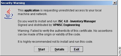
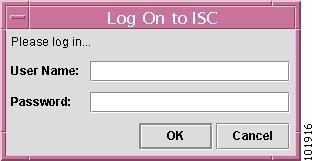
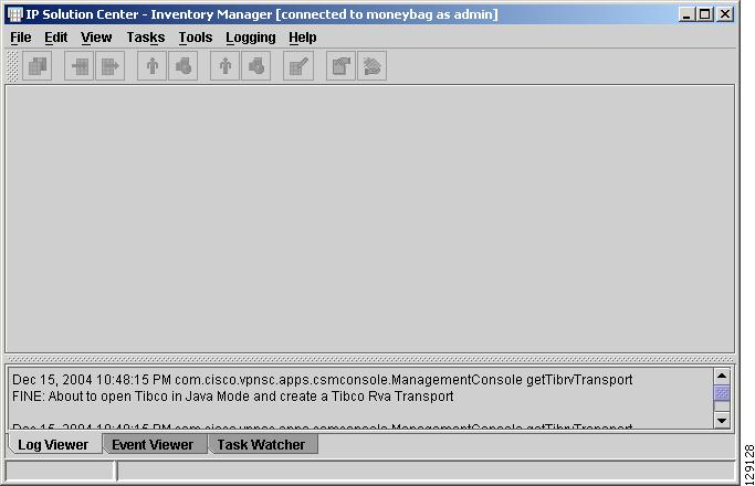
Launching Inventory Manager
To launch Inventory Manager, follow these steps:
Step 1
Step 2
Figure 4-1 Inventory Manager
Step 3
Step 4
Figure 4-2 Start Java Web Start
Step 5
Figure 4-3 Log On to ISC
Step 6
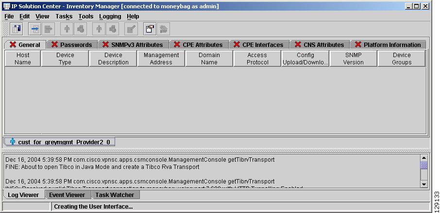
The Inventory Manager Opening Screen in Figure 4-4 appears.
Figure 4-4 Inventory Manager Opening Screen
Importing Devices
As described in the introduction to this chapter, devices can either be imported or created. The fastest way to bring device information into the Repository is to import devices using Inventory Manager.
Importing Devices from Configuration Files
If the configuration files are for a particular customer or provider, you can create a new customer or provider and associate the configuration files with CPEs or PEs. If the customer or provider currently exists in the Repository, you can open them and insert more CPEs or PEs to be associated with new or existing sites or regions.
To import devices with configuration files, follow these steps:
Step 1
This step creates a container for target devices that can be moved to a provider or customer during the initialization process.
Step 2
You receive a prompt to import configuration files. You probably have a repository of configuration files on an existing network management device or TFTP server. Copy these files to the web client machine for import or make them available with a shared directory.
Step 3
The configuration files on the web client can be located by normal file browsing with both Shift and Ctrl+Click selected for multiple selections. When creating a new device group, only one filtering option is available: All Files.
Note
Step 4
You may select multiple configuration files to import using SHIFT or CTRL + click. Please make sure that no more than X (250 or a number to be determined) configuration files are selected for import. There may be performance issues with Inventory Manager if more than X config files are selected for import at once.
Inventory Manager now imports a row in a spreadsheet workbook for each selected configuration file. By default, Inventory Manager inspects the configuration files and determines the device type, which includes Cisco IOS, CatOS, PIX, and VPN 3000 (IPsec, firewall, NAT, VPN 3000: These features are not supported in this release). It also parses passwords, SNMP information, interfaces, and virtual circuits.
If cells in the resulting spreadsheet are empty, Inventory Manager was not able to determine the value and, if it is required, the operator must provide the data or choose the information from a defined set of choices before saving.
These operations are described in more detail in the following sections as they are common to all methods of importing device information and administration.
Step 5
Importing Devices with Auto Discovery
Note
To import devices with Auto Discovery, follow these steps:
Step 1
This creates a spreadsheet where each row represents a potential seed device for discovery. For each seed device, the management interface must be provided. The management interface is the address on the device that the ISC host uses to reach the device.
After creating a new device list, a discovery starting point needs to be configured. This starting point is a device that can be reached from the ISC host. For each seed device, an accessible interface on the starting point is configured, because the management interface must be provided. The management interface is the address on the device that the ISC host uses to reach the device.
New dynamic device discovery requires the following manual tasks:
•
•
A policy.xml file is created and a hop count is set automatically.
To choose the seed devices and hub, pick a seed device that can reach a large section of the network. Pick one or more of them until you think these devices will enable you to reach your entire managed network.
Point-of-presence (POP) routers are usually good choices. If you choose all the POPs in your network as the collection of seed devices and put in the appropriate number of hubs, you discover the entire managed network.
To pick the hub number, go to the CE that is the furthest from its associated POP, and count the number of devices between them. If this number is N, the hub number is N+1, assuming you are picking the POP as the seed.
Step 2
Step 3
A maximum hop count is specified for the Auto Discovery process. The Auto Discovery process queries the starting point device for its CDP table. From this table, all of those devices are queried for their CDP information. This CDP query process continues until the maximum hop count from the starting point is reached. Please note that only devices running the CDP process are discovered.
Step 4
Note
You are prompted to save two files. One file contains the list of the discovered devices and the other contains information related to connectivity between the devices. The discovered device information can be saved in XML to use as a starting point for future discovery efforts.
Step 5
Step 6
Configuring Device Credentials and SNMP Parameters
After the discovered devices are rendered in the spreadsheet, they must have several parameters set before the devices can be saved to the Repository and perform a successful live configuration collection. These parameters include:
•
•
•
Note
First remove any devices that are not required in the provisioning process. These items include core network devices or non-PE, CPE, and CLE devices that are used within the operator's network.
To remove unwanted devices, follow these steps:
Step 1
Shift-select and Control-select are useful for multiple devices.
Step 2
It is common in networks for devices to share many parameters. The Defaults option allows these common parameters to be entered for many devices at the same time; for example, login password, enable password, and SNMP strings.
To edit multiple devices, follow these steps:
Step 1
A row for default values can be edited for each tab of the device list. The next step of the configuration process collects live configurations that require login and enable passwords.
Step 2
After entering the default values, select all of the devices that share those common parameters. For devices that have values other than the default values, you can perform multiple editing techniques.
Step 3
A dialog box, similar to the defaults window appears, allowing you to enter values to be applied to the selection.
Note
Step 4
The management IP address is the address that ISC uses to communicate with the element. This address must be reachable from the ISC host. When the devices were imported or discovered, ISC attempts to select the proper address as a management address starting with a loopback address. Verify the selected address for accessibility from the ISC host. ISC must be able to reach the network element for the configuration process to progress.
Step 5
Collecting Configuration Files
Collecting configuration files serves two purposes. It loads the current configuration information for the device, which populates many of the cells. It also verifies reachability and passwords for the reachable devices.
This task is created in the Repository and starts immediately. Logs can be viewed as normal for a collection spawned using only the Web GUI.
The task name is Inventory_Manager_Collection_xxxxxx_username, where xxxxxx is a unique number and the username is admin, or whatever the logged in username is in ISC.
To collect configurations, follow these steps:
Step 1
Step 2
Marking Interfaces for IPsec, Firewall, NAT, or QoS
IPsec, firewall, NAT: These features are not supported in this release
The interface marking process is only required for provisioning IPsec, Firewall, NAT, or QoS services. Marking interfaces on a one-by-one basis can be a very time consuming and tedious task. Inventory Manager provides a helpful tool to create rules for marking interfaces based on predefined criteria. You can apply one or more rules to selected devices to mark the interfaces in a bulk fashion.
For IPsec, the public interfaces are the interfaces where the IPsec or GRE tunnels terminate and the private interfaces are the interfaces behind which the subnets to be protected reside.
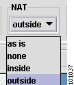
For firewalls, the outside interfaces connect to the outside, typically unsecured, networks and the inside interfaces are for the subnets residing behind the firewall.
To mark interfaces with Inventory Manager, follow these steps:
Step 1
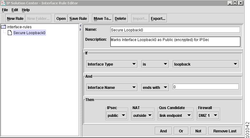
A window appears allowing you to create, modify, or delete existing rules or folders. One simple rule can mark all Loopback0 interfaces as public for IPsec.
Step 2
Step 3
Note
Creating a New Customer with Devices
The devices should now be assigned roles, either PE or CE. For customers, you can assign roles by highlighting each device group and adding it to a new or existing Customer. Routers can be moved in bulk to customers with Inventory Manager.
To move CE routers to a new customer, follow these steps:
Step 1
Step 2
Step 3
A new tab is created at the bottom of the device list and the routers are associated with the customer.
Each customer router must be put into a site. A site can have more than one router in it. All routers in a site should share routing information with the external provider network.
Step 4
Step 5
Step 6
Repeat this process for all the CPEs.
All customer routers must have a Management Type selected. As with customer site, a range of router Management Type cells can be selected for bulk editing.
Step 7
Step 8
Step 9
Creating a New Provider with Devices
A provider or provider administrative domain (PAD) is a group of Provider Edge (PE) devices that share a common BGP AS.
To move PE routers to a new provider and create a region, follow these steps:
Step 1
Step 2
When the devices are assigned a PAD, they become Provider Edge (PE) routers. PEs must be placed into regions. Each PAD must have one or more regions. A region is a collection of PEs that may share an address pool.
Step 3
If the desired region has already been created, it can be selected.
Step 4
You can also add multiple PEs to a single region in one step using standard multiple selection techniques and choosing the Edit > Edit Selected Devices menu. As with single PE editing, you are prompted to choose an existing region or create a new region.
This completes the assignment of roles to devices.
Note
Importing Connections with NPC Auto Discovery
To discover connections, referred to as Named Physical Circuits (NPC), run NPC Auto Discovery. This task defines the PE and CE link information, which is used by Common Discovery in the final stage of the Auto Discovery process. NPC Auto Discovery has one prerequisite, the connection.xml file. Ensure that this file has been uploaded from the ISC server to the client workstation before running this task.
To import connections with NPC Auto Discovery, follow these steps:
Step 1
You are prompted to provide the path to the correct connection.xml file.
Step 2
A dialog box appears, indicating that the NPC discovery process has started.
Step 3
To find the discovered NPCs, go to Service Inventory > Inventory and Connection Manager > Named Physical Circuits.
Importing Services with Service Discovery
At this point, you can choose to run the Common Discovery process. ISC manages Ethernet over MPLS (L2VPN) and MPLS networks with IPsec (IPsec: This feature is not supported in this release). To detect free interfaces on each device for provisioning purposes, existing services either need to be discovered automatically or entered into the system manually.
For very large networks with many provisioned services, manual entry is time consuming and prone to human error. These issues are alleviated by the Common Discovery process. The Common Discovery process discovers:
•
•
•
To specifically import services with Auto Discovery, follow these steps:
Step 1
The Service Discovery window in Figure 4-112 appears (see Start Service Discovery, for the GUI description). You are prompted to select which type of Common Discovery to perform.
Step 2
If you select L2VPN (L2TPv3), the bottom L2TPv3 Options section become available:
Step 3
You are notified when Service Discovery is finished.
Step 4
Introducing the Inventory Manager GUI
Although Inventory Manager has the physical look and feel of many windows applications, with File, Edit, View, Tasks, Tools, Logging, and Help menus, the application is designed to have the logical view of a spreadsheet. When you learn how to use one spreadsheet in Inventory Manager, you learn how to use them all.
After starting up Inventory Manager by following the steps outlined in Launching Inventory Manager, the main Inventory Manager window in Figure 4-4 appears.
Figure 4-5 Inventory Manager GUI
The various GUI elements are explained in the following sections and in Inventory Manager GUI Reference.
This section contains the following sections:
Spreadsheet Features
This section contains the following sections:
•
Understanding the Spreadsheet
Before using Inventory Manager, you need to know about these spreadsheet features:
•
–
–
–
•
–
–
–
–
–
•
–
•
–
–
–
–
–
–
•
–
–
–
•
–
–
–
–
Note
Editing the Spreadsheet
When you learn how to set defaults or edit columns in one spreadsheet, you can set defaults or edit columns for each type of spreadsheet in Inventory Manager.
Cell Editing
Cell editing has the following features:
•
•
•
•
•
Cells
Cells have the following editing features:
•
•
•
•
Note
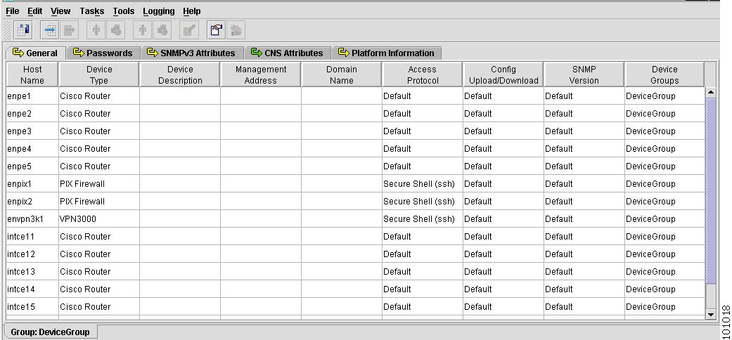
Provider Spreadsheet
The Provider spreadsheets contain the following tabs:
General
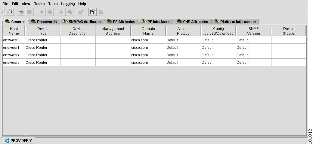
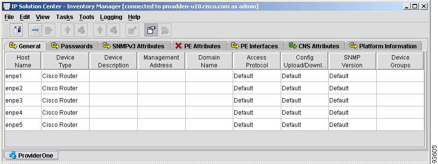
Figure 4-6 shows an example of the General tab:
Figure 4-6 Provider Spreadsheet - General Tab
The General tab contains the following columns:
•
•
–
–
–
–
–
–
•
•
•
•
•
•
•
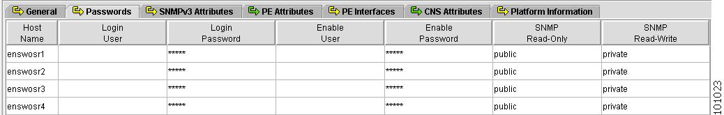
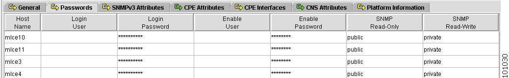
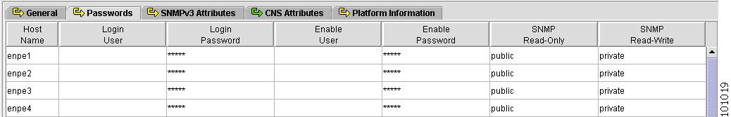
Passwords
Figure 4-7 shows an example of the Passwords tab:
Figure 4-7 Provider Spreadsheet - Password Tab
The Passwords tab contains the following columns:
•
•
•
•
•
•
•
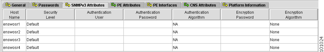
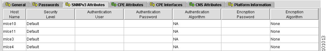
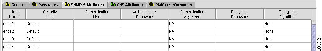
SNMPv3 Attributes
Figure 4-8 shows an example of the SNMPv3 Attributes tab:
Figure 4-8 Provider Spreadsheet - SNMPv3 Attributes Tab
The SNMPv3 Attributes contains the following columns:
•
•
•
•
•
•
•
Note
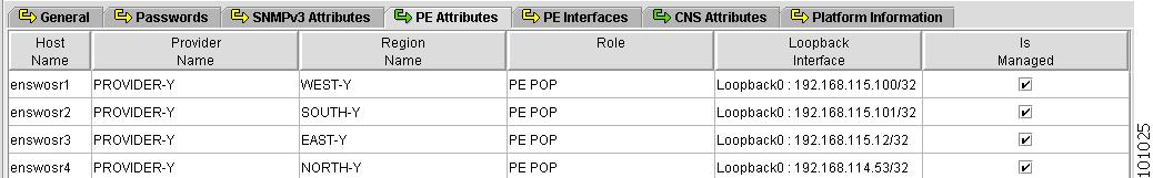
PE Attributes
Figure 4-9 shows an example of the PE Attributes tab:
Figure 4-9 Provider Spreadsheet - PE Attributes Tab
The PE Attributes tab contains the following columns:
•
•
•
•
•
•
PE Interfaces
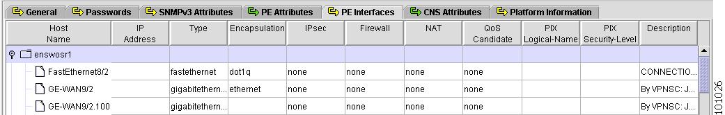
Figure 4-10 shows an example of the PE Interfaces tab:
Figure 4-10 Provider Spreadsheet - PE Interfaces Tab
The PE Interfaces tab contains the following columns:
•
•
•
–
–
–
–
–
–
–
•
–
–
–
–
–
–
–
–
–
–
–
–
–
–
–
–
–
–
•
View or edit (mark) interface settings for IPsec. Choices include:–
–
Interface to the public network (internet). All traffic is encrypted.
–
Interface to the private network (internal LAN). All traffic is not encrypted.
•
View or edit (mark) interface settings for Firewall. If Device Type is VPN 3000, Firewall is not available. Choices include:–
Highest security interface.
–
Lowest security interface.
–
The Demilitarized Zone services to both inside and outside interfaces.
•
View or edit (mark) interface settings for NAT. If Device Type is PIX firewall or VPN 3000, NAT is not available. Choices include:–
–
Highest security interface.
–
Lowest security interface.
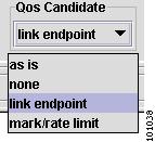
•
–
–
This setting marks the Customer LAN facing interface with the set and police commands.
–
This setting marks the PE facing interface on the CE device and the CE facing interface on the PE device.
On the PE side, all QoS commands go on this interface.
On the CE side, all QoS commands, including the set and police commands, go on this interface if no interface on the CE device is identified as the Marking Rate Limit interface.
If one or more interfaces have been identified as Marking Rate Limit interfaces, then all QoS commands except the set and police commands go on this interface.
•
•
•
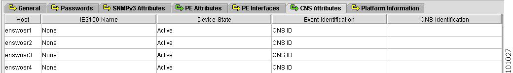
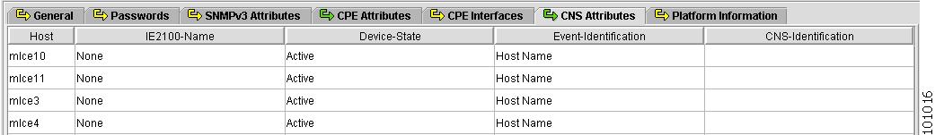
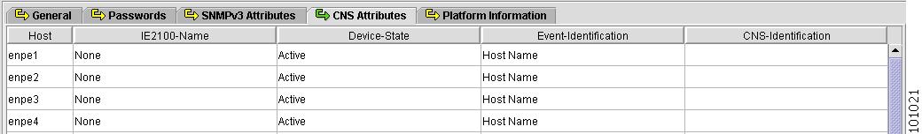
CNS Attributes
Figure 4-11 shows an example of the CNS Attributes tab:
Figure 4-11 Provider Spreadsheet - CNS Attributes Tab
The CNS Attributes tab contains the following columns:
•
•
•
•
•
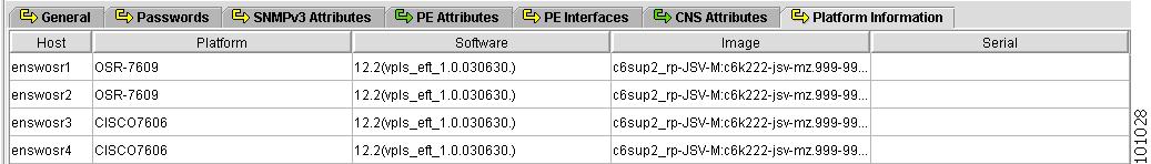
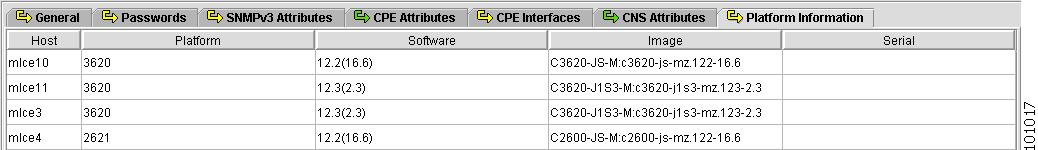
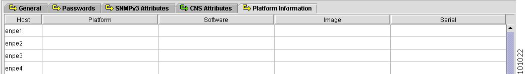
Platform Information
Figure 4-12 shows an example of the Platform Information tab. These fields are typically filled in from the physical device during the collection process.
Figure 4-12 Provider Spreadsheet - Platform Information Tab
The Platform Information tab contains the following columns:
•
•
•
•
•
Customer Spreadsheet
The Customer spreadsheets contain the following tabs:
General
Figure 4-13 shows an example of the General tab:
Figure 4-13 Customer Spreadsheet - General Tab
The General tab contains the following columns:
•
•
–
–
–
–
–
–
•
•
•
•
•
•
•
Passwords
Figure 4-14 shows an example of the Passwords tab:
Figure 4-14 Customer Spreadsheet - Passwords Tab
The Passwords tab contains the following columns:
•
•
•
•
•
•
•
SNMPv3 Attributes
Figure 4-15 shows an example of the SNMPv3 Attributes tab:
Figure 4-15 Customer Spreadsheet - SNMPv3 Attributes Tab
The SNMPv3 Attributes contains the following columns:
•
•
•
•
•
•
•
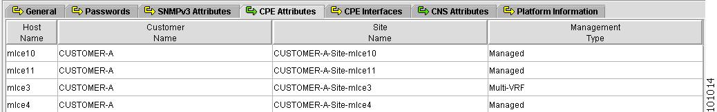
CPE Attributes
Figure 4-16 shows an example of the CPE Attributes tab:
Figure 4-16 Customer Spreadsheet - CPE Attributes Tab
The CPE Attributes tab contains the following columns:
•
•
•
•
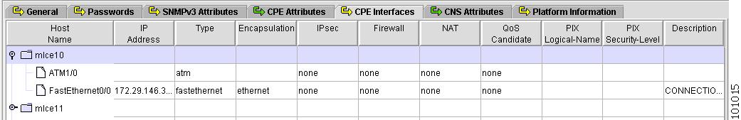
CPE Interfaces
Figure 4-17 shows an example of the CPE Interfaces tab:
Figure 4-17 Customer Spreadsheet - CPE Interfaces Tab
The CPE Interfaces tab contains the following columns:
•
•
•
•
–
–
–
–
–
–
–
–
–
–
–
–
–
–
–
–
–
–
•
View or edit (mark) interface settings for IPsec. Choices include:–
–
Interface to the public network (internet). All traffic is encrypted.
–
Interface to the private network (internal LAN). All traffic is not encrypted.
•
View or edit (mark) interface settings for Firewall. If Device Type is VPN 3000, Firewall is not available. Choices include:–
Highest security interface.
–
Lowest security interface.
–
The Demilitarized Zone services to both inside and outside interfaces.
•
View or edit (mark) interface settings for NAT. If Device Type is PIX firewall or VPN 3000, NAT is not available. Choices include:–
–
Highest security interface.
–
Lowest security interface.
•
–
–
This setting marks the Customer LAN facing interface with the set and police commands.
–
This setting marks the PE facing interface on the CE device and the CE facing interface on the PE device.
On the PE side, all QoS commands go on this interface.
On the CE side, all QoS commands, including the set and police commands, go on this interface if no interface on the CE device is identified as the Marking Rate Limit interface.
If one or more interfaces have been identified as Marking Rate Limit interfaces, then all QoS commands except the set and police commands go on this interface.
•
•
•
CNS Attributes
Figure 4-18 shows an example of the CNS Attributes tab:
Figure 4-18 Customer Spreadsheet - CNS Attributes Tab
The CNS Attributes tab contains the following columns:
•
•
•
•
•
Platform Information
Figure 4-19 shows an example of the Platform Information tab. These fields are typically filled in from the physical device during the collection process.
Figure 4-19 Customer Spreadsheet - Platform Information Tab
The Platform Information tab contains the following columns:
•
•
•
•
•
Device Group Spreadsheet
The Device Group spreadsheets contain the following tabs:
General
Figure 4-20 shows an example of the General tab:
Figure 4-20 Device Group Spreadsheet - General Tab
The General tab contains the following columns:
•
•
–
–
–
–
–
–
•
•
•
•
•
•
•
Passwords
Figure 4-21 shows an example of the Passwords tab:
Figure 4-21 Device Group Spreadsheet - Passwords Tab
The Passwords tab contains the following columns:
•
•
•
•
•
•
•
SNMPv3 Attributes
Figure 4-22 shows an example of the SNMPv3 Attributes tab:
Figure 4-22 Device Group Spreadsheet - SNMPv3 Attributes Tab
The SNMPv3 Attributes contains the following columns:
•
•
•
•
•
•
•
CNS Attributes
Figure 4-23 shows an example of the CNS Attributes tab:
Figure 4-23 Device Group Spreadsheet - CNS Attributes Tab
The CNS Attributes tab contains the following columns:
•
•
•
•
•
Platform Information
Figure 4-24 shows an example of the Platform Information tab. These fields are typically filled in from the physical device during the collection process.
Figure 4-24 Device Group Spreadsheet - Platform Information Tab
The Platform Information tab contains the following columns:
•
•
•
•
•
Inventory Manager GUI Reference
This section describes the Inventory Manager GUI. It is organized by the external design of the GUI: what you see when you look at the windows, menus, and options. It is intended for new users who want to get started with Inventory Manager, and for experienced users who need a reference for the GUI workflow.
To access the Inventory Manager GUI, follow these steps:
Step 1
Step 2
Step 3
After initializing Java Web Start, Inventory Manager appears, as shown in Figure 4-25.
Figure 4-25 Inventory Manager
You now have access to the Inventory Manager Task Bar.
This section contains a section for each Inventory Manager menu:
•
Viewer and Task Watcher Tabs
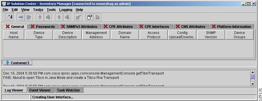
The tabs at the bottom of the main Inventory Manager GUI in Figure 4-4 are used to monitor events and perform troubleshooting.
They serve the following purpose:
•
•
•
File Menu
The File menu has the following options:
•
•
•
•
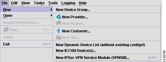
New
From the Inventory Manager main menu, New is the first option under the File menu on the Task Bar. The New option has the following options:
•
•
Additionally, Open, is an option from alternate tabs.
New Device Group
To create a new Device Group, follow these steps:
Step 1
Figure 4-26 Choose New Device Group
The New Device Group window appears, as shown in Figure 4-27.
Note
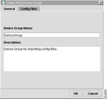
Figure 4-27 Create New Device Group
Step 2
Step 3
Step 4
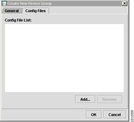
The Config Files tab appears, as shown in Figure 4-28.
Figure 4-28 Config Files Tab
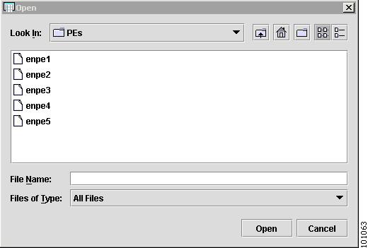
Step 5
Step 6
The Open Config Files window appears, as shown in Figure 4-29.
Figure 4-29 Open Config Files
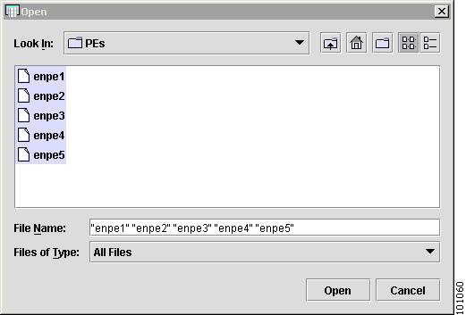
Step 7
The files appear highlighted, as shown in Figure 4-30.
Figure 4-30 Highlighted Config Files
Step 8
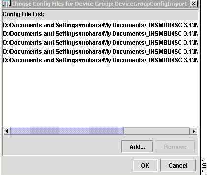
The Config File List appears, as shown in Figure 4-31.
Figure 4-31 Config Files List
Step 9
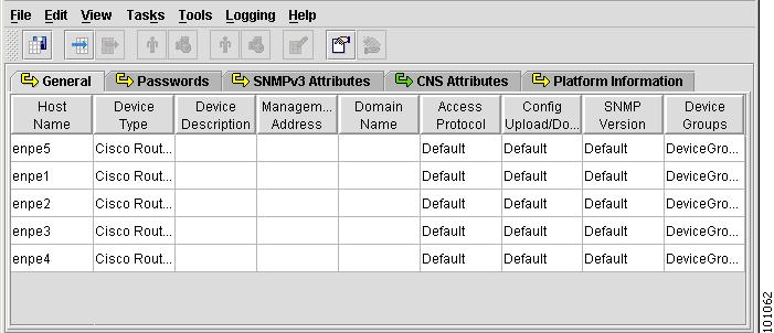
The Device Group spreadsheet appears, as shown in Figure 4-32.
Figure 4-32 Device Group Spreadsheet
When you create devices this way, no CPEs or PEs are created. To create CPEs or PEs, devices must be associated with a Customer, Site, Provider, or Region.
You have created a new Device Group and added the configuration files. The Spreadsheet Editor enables you to specify attributes for the devices. The following examples show how to edit or specify fields in the device workbook.
Cell Editing Examples
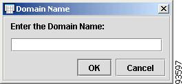
To enter the Domain Name, click the cell. The Domain Name dialog box appears, as shown in Figure 4-33.
Figure 4-33 Domain Name
Enter the Domain Name and click OK.
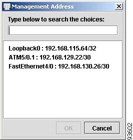
To enter the Management Address, click the cell. The Management Address dialog box appears, as shown in Figure 4-34.
Figure 4-34 Management Address
Enter the Management Address, or select one from the list, and click OK.
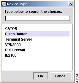
To enter the Device Type, click the cell. The Device Type dialog box appears, as shown in Figure 4-35.
Figure 4-35 Device Type
Enter the Device Type, or select one from the list, and click OK.
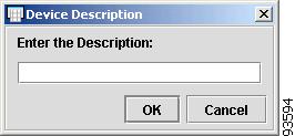
To enter the Device Description, click the cell. The Device Description dialog box appears, as shown in Figure 4-36.
Figure 4-36 Device Description
Enter the Device Description and click OK.
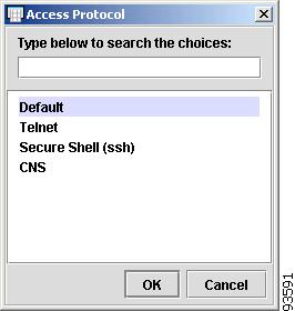
To enter the Access Protocol, click the cell. The Access Protocol dialog box appears, as shown in Figure 4-37.
Figure 4-37 Access Protocol
Enter the Access Protocol, or select one from the list, and click OK.
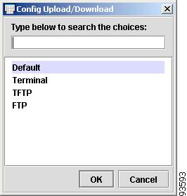
To enter the Config Upload/Download, click the cell. The Config Upload/Download dialog box appears, as shown in Figure 4-38.
Figure 4-38 Config Upload/Download
Enter the Config Upload/Download, or select one from the list, and click OK.
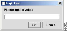
To enter the Login User, click the cell. The Login User dialog box appears, as shown in Figure 4-39.
Figure 4-39 Login User
Enter the Login User and click OK.
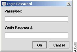
To enter the Login Password, click the cell. The Login Password dialog box appears, as shown in Figure 4-40.
Figure 4-40 Login Password
Enter the Login Password in both dialog boxes and click OK.
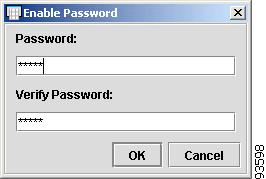
To enter the Enable Password, click the cell. The Enable Password dialog box appears, as shown in Figure 4-41.
Figure 4-41 Enable Password
Enter the Enable Password in both dialog boxes and click OK.
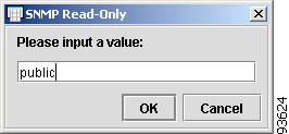
To enter the SNMP Read-Only, click the cell. The SNMP Read-Only dialog box appears, as shown in Figure 4-42.
Figure 4-42 SNMP Read-Only
Enter the SNMP Read-Only value, or select one from the list, and click OK.
To enter the SNMP Read-Write value, click the cell. The SNMP Read-Write dialog box appears, as shown in Figure 4-43.
Figure 4-43 SNMP Read-Write
Enter the SNMP Read-Write value, or select one from the list, and click OK.
Step 10
New Provider
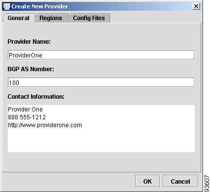
To create a new Provider, follow these steps:
Note
Step 1
The New Provider window appears, as shown in Figure 4-44.
Figure 4-44 New Provider
Step 2
Step 3
Step 4
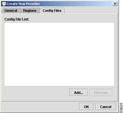
Step 5
The Config Files tab appears, as shown in Figure 4-45.
Figure 4-45 Config Files Tab
Step 6
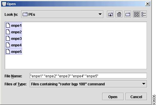
Step 7
The Open Config Files window appears.
Step 8
The files appear highlighted, as shown in Figure 4-46.
Figure 4-46 Highlighted Config Files
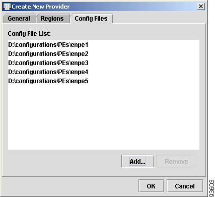
Step 9
The Config File List appears, as shown in Figure 4-47.
Figure 4-47 Config Files List
Step 10
The New Provider spreadsheet appears, as shown in Figure 4-48.
Figure 4-48 New Provider Spreadsheet
You have created a new Provider and added the configuration files. The Spreadsheet Editor enables you to specify attributes for the devices. When you create devices this way, PEs are created.
To finish, choose File > Save.
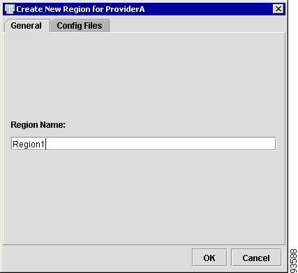
New Region
To create a new Region, follow these steps:
Note
Step 1
The New Region for Provider window appears, as shown in Figure 4-49.
Figure 4-49 New Region for Provider
Step 2
The Inventory Manager menu appears with a spreadsheet for the Provider, as shown in Figure 4-50.
Figure 4-50 New Provider Spreadsheet
For a description of the tabs and definition of the fields in the Provider, Region, and PE spreadsheets, see the "Spreadsheet Features" section.
New Customer
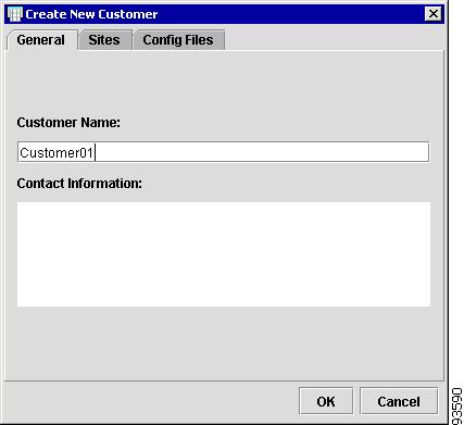
To create a new Customer, follow these steps:
Note
Step 1
The New Customer window appears, as shown in Figure 4-51.
Figure 4-51 New Customer
Step 2
Step 3
The Inventory Manager menu appears with a spreadsheet for the Customer, as shown in Figure 4-52.
Figure 4-52 New Customer Spreadsheet
You now have access to the Customer spreadsheet.
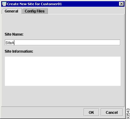
New Site
To create a new Site, follow these steps:
Note
Step 1
Figure 4-53 New Site
Step 2
Step 3
The Inventory Manager menu appears with a spreadsheet for the Customer, as shown in Figure 4-54.
Figure 4-54 New Customer Spreadsheet
You now have access to the Customer spreadsheet.
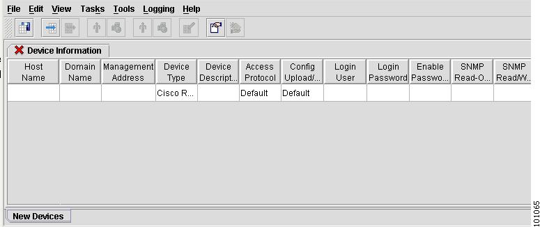
New Dynamic Device List (without existing configs)
If you do not have existing configuration files, you can discover devices on your network, using the Dynamic Device List. The devices can be associated with logical CPE and PE devices at a later time.
To create a new Device List, follow these steps:
Step 1
A new Device Spreadsheet appears, as shown in Figure 4-55.
Figure 4-55 New Device Spreadsheet
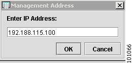
Step 2
A Management Address window appears, as shown in Figure 4-56.
Figure 4-56 Enter IP Address
Step 3
A new Device Spreadsheet appears.
Step 4
For an example of how to start the device discovery process, see the "Start Auto Discovery" section.
New IE2100 Device List
ISC supports the Cisco CNS IE2100 appliance Device Access Protocol for communication with any Cisco IOS device. Inventory Manager supports the same functionality for the Cisco CNS IE2100 appliance as the other devices described in the chapter.
New IPsec VPN Service Module (VPNSM)
This feature is not supported in this release
To create a new VPNSM Device, follow these steps:
Step 1
Figure 4-57 Choose New IPsec VPN Service Module
The New IPsec VPN Service Module spreadsheet appears, as shown in Figure 4-58.
Figure 4-58 Create New IPsec VPN Service Module
Step 2
The Catalyst 6500 window appears (not shown).
Step 3
Step 4
Step 5
Open
From the Inventory Manager main menu, shown in Figure 4-26, Open is the second option under the File menu on the Task Bar. The Open option has the following options:
•
Open Devices
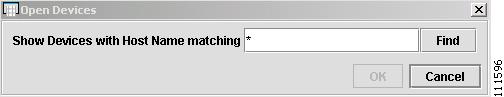
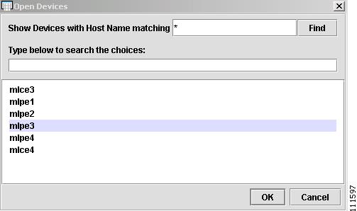
This section describes how to open a Device with Inventory Manager. To open a Device, follow these steps:
Step 1
The Open Devices window appears, as shown in Figure 4-59.
Figure 4-59 Open Devices
Step 2
The Open Devices window now displays available devices, as shown in Figure 4-60.
Figure 4-60 Open Devices Found
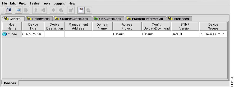
Step 3
The Devices spreadsheet appears, as shown in Figure 4-61.
Figure 4-61 Devices Spreadsheet
Open Discovery Seed File
Note
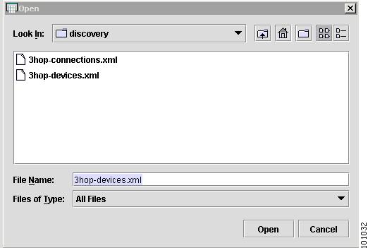
To open a discovery seed file, follow these steps:
Step 1
The Open window appears, as shown in Figure 4-62.
Figure 4-62 Open Discovery Seed File
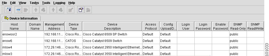
Step 2
The Device Information spreadsheet appears, as shown in Figure 4-63.
Figure 4-63 Device Information
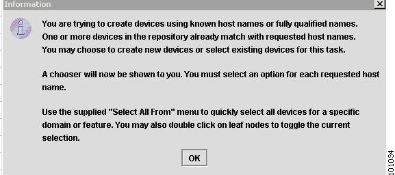
If a device has already been created in the Repository, a message window appears, as shown in Figure 4-64.
Figure 4-64 Device in the Repository
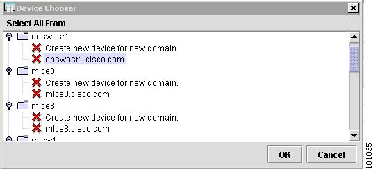
Step 3
Figure 4-65 Device Chooser
Step 4
The Device Information spreadsheet appears, as shown in Figure 4-66.
Figure 4-66 Device Information
Now you can edit your devices and collect the latest configuration files.
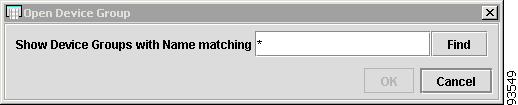
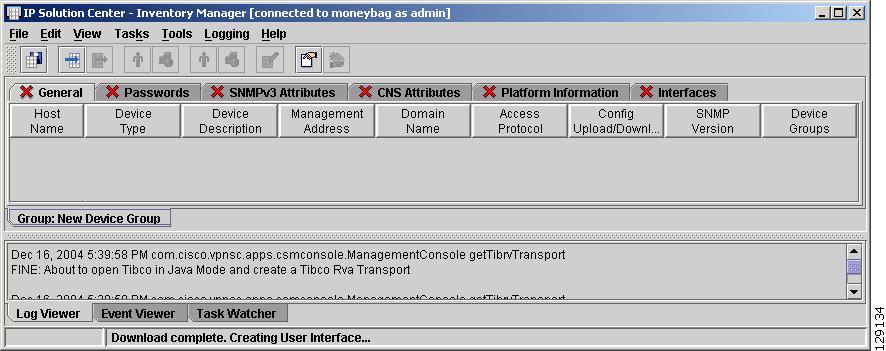
Open Device Group
To open an existing Device Group, follow these steps:
Step 1
A search dialog appears, as shown in Figure 4-67.
Figure 4-67 Open Device Group
Step 2
Step 3
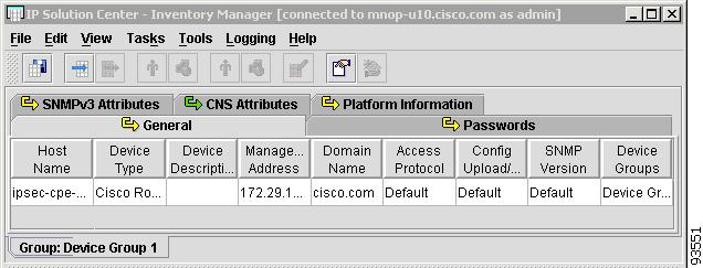
A Device Spreadsheet Editor appears, where you can edit device parameters such as passwords and SNMP information, as shown in Figure 4-68.
Figure 4-68 Device Spreadsheet Editor
You now have access to the Device spreadsheet.
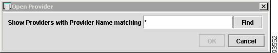
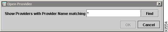
Open Provider
To open an existing Provider, follow these steps:
Step 1
A search dialog appears, as shown in Figure 4-69.
Figure 4-69 Open Provider
Step 2
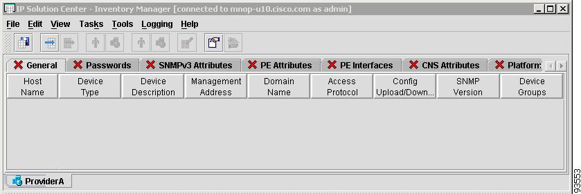
Step 3
A PE Spreadsheet Editor appears with all Regions and PEs for that Provider listed in the Spreadsheet Editor, as shown in Figure 4-70.
Note
Figure 4-70 Provider Spreadsheet Editor
You now have access to the Provider spreadsheet.
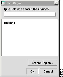
Open Region
To open an existing Region, follow these steps:
Step 1
A search dialog appears, as shown in Figure 4-71.
Figure 4-71 Open Provider
Step 2
Step 3
Step 4
You can also create a Region for the Provider by choosing Create Region.
Figure 4-72 Open Region
A PE Spreadsheet Editor appears with all PEs for the Region listed in the Spreadsheet Editor, as shown in Figure 4-73.
Figure 4-73 PE Spreadsheet Editor
You now have access to the Provider spreadsheet.
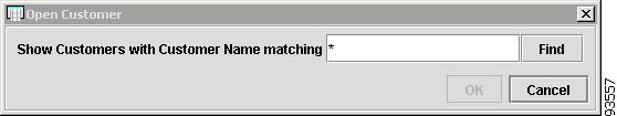
Open Customer
To open an existing Customer, follow these steps:
Step 1
A search dialog appears, as shown in Figure 4-74.
Figure 4-74 Open Customer
Step 2
Step 3
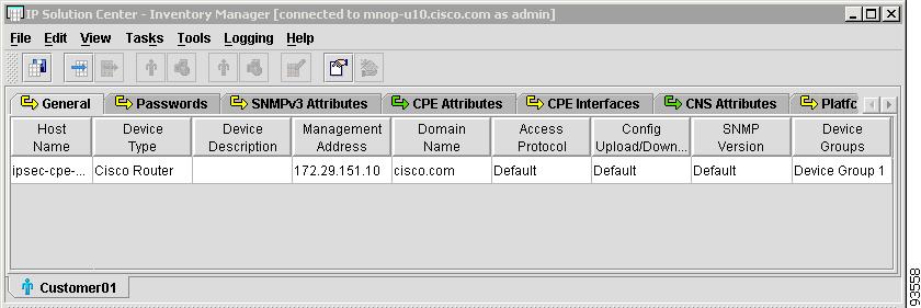
A CPE Spreadsheet Editor appears with all Sites and CPE for the Customer listed in the Spreadsheet Editor, as shown in Figure 4-75.
Figure 4-75 CPE Spreadsheet Editor
You now have access to the Customer spreadsheet.
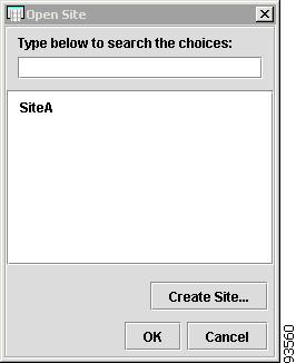
Open Site
To open an existing Site, follow these steps:
Step 1
A search dialog appears, as shown in Figure 4-76.
Figure 4-76 Open Customer
Step 2
Step 3
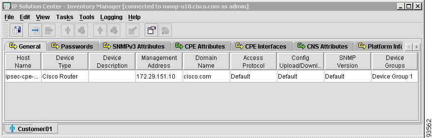
Choose from the list of existing Sites, as shown in Figure 4-77. You can also create a Site for the Customer by choosing Create Site.
Figure 4-77 Open Site
A CPE Spreadsheet Editor appears with all the CPEs for that Site listed in the Spreadsheet Editor, as shown in Figure 4-78.
Figure 4-78 CPE Spreadsheet Editor
You now have access to the Customer spreadsheet.
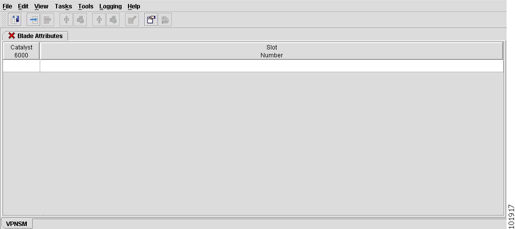
Open IPsec VPN Service Modules
This feature is not supported in this release
To open an existing VPNSM, follow these steps:
Step 1
Open Device Blades window appears (not shown).
Step 2
Step 3
Required Attributes
From the Inventory Manager main menu, shown in Figure 4-26, Required Attributes is the third option under the File menu on the Task Bar. To specify required attributes, you must open a Spreadsheet Editor for one of the following options:
•
•
•
•
•
•
•
•
The Spreadsheet Editors work the same for each inventory group. They default to the General tab and display a list of attributes. Some attributes in each Spreadsheet Editor are required and others are not. You can make some of the non-system required attributes required by clicking a checkbox for that attribute.
If an attribute is required, the spreadsheet tab will have a red X indicating that more information is required by the system for all later processing to proceed without errors. For example, errors can occur when processing service requests or creating a VPN. When all required information is filled out, the red X changes to either a yellow or green Continue Image. When you see a red X on a tab, it means you need to fill out more information for the tab.
From the Required Attributes option, you can specify required attributes for the following inventory groups:
Device Groups
To specify required attributes for a Device Group, follow these steps:
Step 1
A search dialog appears.
Step 2
Figure 4-79 Open Device Group
Step 3
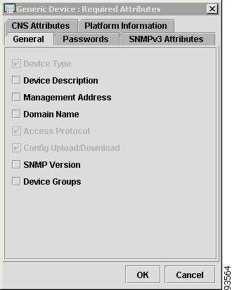
The General tab on the Required Attributes window for a Device Group appears, as shown in Figure 4-80.
Step 4
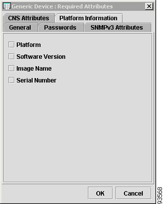
Figure 4-80 Generic Device - General Attributes
The General tab contains the following attributes:
•
•
•
•
•
•
•
•
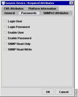
Step 5
The Passwords tab on the Required Attributes window appears, as shown in Figure 4-81.
Step 6
Figure 4-81 Generic Device - Password Attributes
The Passwords tab contains the following attributes:
•
•
•
•
•
•
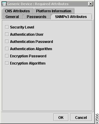
Step 7
The SNMPv3 tab on the Required Attributes window appears, as shown in Figure 4-82.
Step 8
Figure 4-82 Generic Device - SNMPv3 Attributes
The SNMPv3 Attributes tab contains the following attributes:
•
•
•
•
•
•
Step 9
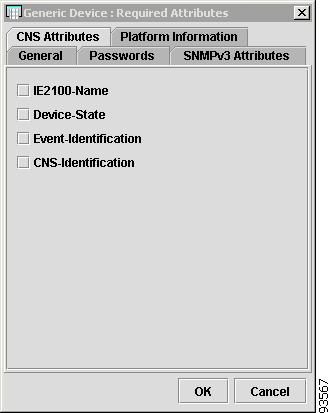
The CNS tab on the Required Attributes window appears, as shown in Figure 4-83.
Step 10
Figure 4-83 Generic Device - CNS Attributes
The CNS Attributes tab contains the following attributes:
•
•
•
•
Step 11
The Platform Information tab on the Required Attributes window appears, as shown in Figure 4-84.
Step 12
Figure 4-84 Generic Device - Platform Information Attributes
The Platform Information tab contains the following attributes:
•
•
•
•
Providers, Regions, and PE
To specify required attributes for a Provider, follow these steps:
Step 1
A search dialog appears.
Step 2
Figure 4-85 Open Provider
Step 3
The General tab on the Required Attributes window for the provider appears, as shown in Figure 4-86.
Step 4
Figure 4-86 PE Device - General Attributes
The General tab contains the following attributes:
•
•
•
•
•
•
•
•
Step 5
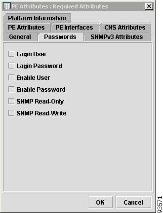
The Passwords tab on the Required Attributes window appears, as shown in Figure 4-87.
Step 6
Figure 4-87 PE Device - Password Attributes
The Passwords tab contains the following attributes:
•
•
•
•
•
•
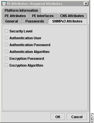
Step 7
The SNMPv3 Attributes tab on the Required Attributes window appears, as shown in Figure 4-88.
Step 8
Figure 4-88 PE Device - SNMPv3 Attributes
The SNMPv3 Attributes contains the following attributes:
•
•
•
•
•
•
Step 9
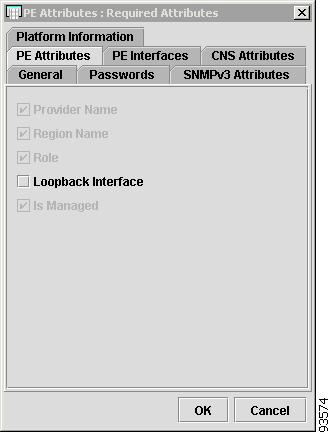
The PE Attributes tab on the Required Attributes window appears, as shown in Figure 4-89.
Step 10
Figure 4-89 PE Device - PE Attributes
The PE Attributes tab contains the following attributes:
•
•
•
•
•
Step 11
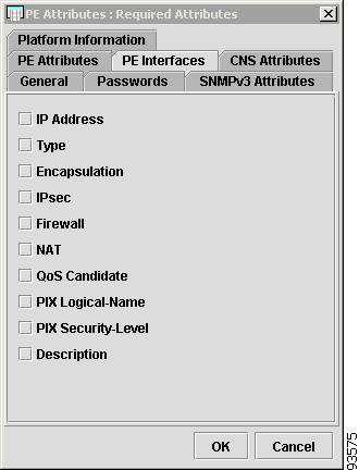
The PE Interfaces tab on the Required Attributes window appears, as shown in Figure 4-90.
Step 12
Figure 4-90 PE Device - PE Interfaces
The PE Interfaces tab contains the following attributes:
•
•
•
•
•
•
•
•
•
•
Step 13
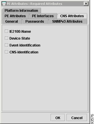
The CNS Attributes tab on the Required Attributes window appears, as shown in Figure 4-91.
Step 14
Figure 4-91 PE Device - CNS Attributes
The CNS Attributes tab contains the following attributes:
•
•
•
•
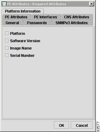
Step 15
The Platform Information tab on the Required Attributes window appears, as shown in Figure 4-92.
Step 16
Figure 4-92 PE Device - Platform Information
The Platform Information tab contains the following attributes:
•
•
•
•
Customers, Sites, and CE
To specify required attributes for a Customer, follow these steps:
Step 1
A search dialog appears.
Step 2
Figure 4-93 Open Customer
Step 3
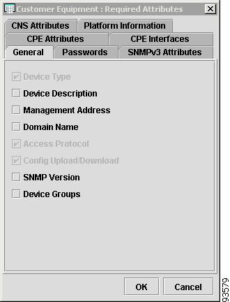
The General tab on the Required Attributes window appears, as shown in Figure 4-94.
Step 4
Figure 4-94 CPE Device - General Attributes
The General tab contains the following attributes:
•
•
•
•
•
•
•
•
Step 5
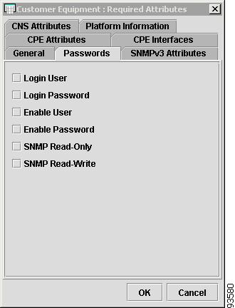
The Passwords tab on the Required Attributes window appears, as shown in Figure 4-95.
Step 6
Figure 4-95 CPE Device - Password Attributes
The Passwords tab contains the following attributes:
•
•
•
•
•
•
Step 7
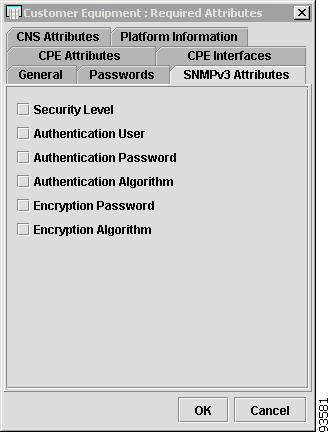
The SNMPv3 Attributes tab on the Required Attributes window appears, as shown in Figure 4-96.
Step 8
Figure 4-96 CPE Device - SNMPv3 Attributes
The SNMPv3 Attributes contains the following attributes:
•
•
•
•
•
•
Step 9
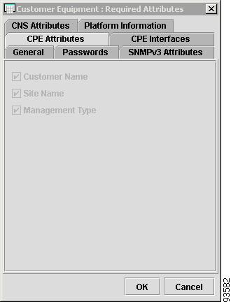
The CPE Attributes tab on the Required Attributes window appears, as shown in Figure 4-97.
Step 10
Figure 4-97 CPE Device - CPE Attributes
The CPE Attributes tab contains the following attributes:
•
•
•
Step 11
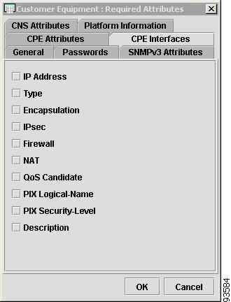
The CPE Interfaces tab on the Required Attributes window appears, as shown in Figure 4-98.
Step 12
Figure 4-98 CPE Device - CPE Interfaces
The CPE Interfaces tab contains the following attributes:
•
•
•
•
•
•
•
•
•
•
Step 13
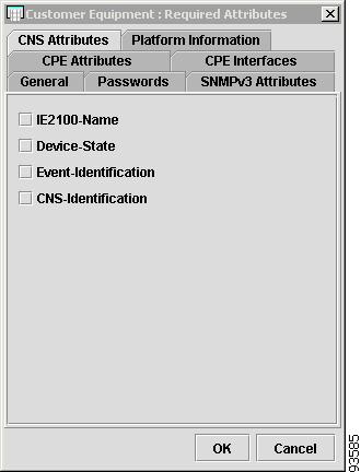
The CNS Attributes tab on the Required Attributes window appears, as shown in Figure 4-99.
Step 14
Figure 4-99 CPE Device - CNS Attributes
The CNS Attributes tab contains the following attributes:
•
•
•
•
Step 15
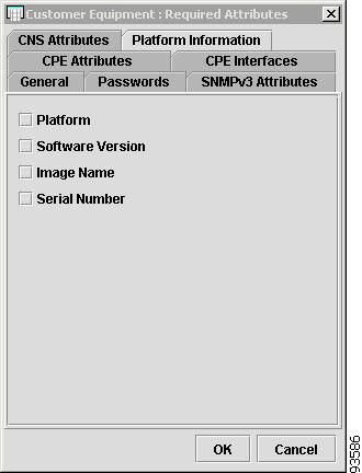
The Platform Information tab on the Required Attributes window appears, as shown in Figure 4-100.
Step 16
Figure 4-100 CPE Device - Platform Information Attributes
The Platform Information tab contains the following attributes:
•
•
•
•
Save
From the Inventory Manager main menu, shown in Figure 4-26, Save is the fourth option under the File menu on the Task Bar.
This option saves your work.
Close
From the Inventory Manager main menu, shown in Figure 4-26, Close is the fifth option under the File menu on the Task Bar.
This option name changes depending on which Spreadsheet Editor you choose. For example, if you are editing a Customer named CustomerA, the menu would show File Close CustomerA.
If there are changes to be saved, the system prompts you to save, and then the Spreadsheet Editor closes. You have an opportunity to cancel the operation if saving is required.
Exit
From the Inventory Manager main menu, shown in Figure 4-26, Exit is the sixth option under the File menu on the Task Bar.
This option shuts down the Inventory Manager. If there are changes to be made, the system prompts you to save changes before exiting.
Edit Menu
From the Inventory Manager main menu, shown in Figure 4-25, Edit is the second menu on the Task Bar. The Edit menu has the following options:
•
•
Insert More Devices
When editing a Device Group, Provider, or Customer, choosing this option causes a File Open Dialog to appear, where you can select more configuration files to be inserted. A new row is created for each new configuration file that is added:
•
•
•
•
To insert more devices in a Spreadsheet Editor, choose Edit > Insert More Devices from the Inventory Manager Task Bar.
Remove Selected Devices
When editing a Device Group, Provider, or Customer, choosing this option allows selected rows to be removed from the spreadsheet.
To delete rows in a Spreadsheet Editor, choose Remove Selected Devices from the Inventory Manager Task Bar.
Use the Host Name Column to select rows of device information. A confirmation dialog appears. If you choose Yes, the selected rows are removed from the Spreadsheet Editor.
Note
Move to New Customer
This option is enabled only when you create devices using the Open Discovery Seed File or New Dynamic Device List options. You must select rows using the Host Name Column or the Select All option. The selected rows in the spreadsheet are moved to a new tab for a Customer in a CPE Spreadsheet Editor.
To create a new Customer and move the selected rows to a new CPE Spreadsheet Editor, follow these steps:
Step 1
Step 2
Step 3
Step 4
Step 5
Move to New Provider
This option is enabled only when you create devices using the Open Discovery Seed File or New Dynamic Device List options. You must select rows using the Host Name Column or the Select All option. The selected rows in the spreadsheet are moved to a new tab for a Provider in a PE Spreadsheet Editor.
To create a new Provider and move the selected rows to a new PE Spreadsheet Editor, follow these steps:
Step 1
Step 2
Step 3
Step 4
Step 5
Move to Customer
This option is enabled only when you create devices using the Open Discovery Seed File or New Dynamic Device List. You must use the Host Name Column or the Select All options to select rows. The selected rows in the spreadsheet are moved to a new tab for the customer in a CPE Spreadsheet Editor.
To select rows in a table, open an existing customer, and move the rows to a new CPE Spreadsheet Editor, and follow these steps:
Step 1
Step 2
A dialog box appears asking you to enter the existing Customer name.
Step 3
Step 4
If you click OK, the selected rows are removed from the current spreadsheet into an existing customer CPE spreadsheet.
Note
Edit the CPEs as you would for any customer by associating them with new or existing Region objects. If the originating spreadsheet is empty after the operation, it automatically closes.
Move to Provider
This option is enabled only when you create devices using the Open Discovery Seed File or New Dynamic Device List. You must use the Host Name Column or the Select All options to select rows. The selected rows in the spreadsheet are moved to a new tab for the Provider in a PE Spreadsheet Editor.
To select rows in a table, open an existing provider, and move the rows to a new PE Spreadsheet Editor, and follow these steps:
Step 1
Step 2
A dialog box appears asking you to enter the existing Provider name.
Step 3
Step 4
If you click OK, the selected rows are removed from the current spreadsheet into an existing Provider PE spreadsheet.
Note
Step 5
Edit Selected Devices
To edit selected devices from rows in a spreadsheet, follow these steps:
Step 1
A Multi-Attribute Cell Editor appears where you can set a value that is applied to all selected cells for each respective column in the selection.
Step 2
Step 3
A column-specific editor appears.
Step 4
A new dialog appears showing a table with one row. Each column containing selected cells in the originating spreadsheet is represented in the dialog.
Step 5
Step 6
Step 7
You are prompted with a search dialog to specify the value. The type of search dialog depends on the column you are editing. For example, if you edit a username you are prompted with a single input editor. If you are editing a password column, you get a password editor.
To edit multiple attributes at one time, select the cells using the following standard techniques for multiple selections:
•
•
•
•
Edit Default Attributes
Each spreadsheet editor (Device Group, CPE, PE, and Dynamic Device List) has the ability to store separate default attributes. Defaults for passwords and other parameters for PEs can be different from those of CPEs.
For example, all PEs in a provider network can share the same passwords, SNMP attributes, and so on. Using Inventory Manager, you can store default attributes for most of the attributes in each spreadsheet. These default attributes can then be applied to selected cells using the Edit > Load Default Attributes to Selected Cells menu.
To edit default attributes, follow these steps:
Step 1
A new dialog appears containing a table with one row.
Step 2
Step 3
Each specific Spreadsheet Editor has its own unique set of columns. Each editor allows the specification for default values to be stored and retrieved at a later time. It is the standard spreadsheet format, and to specify the values you must click on each cell. These values are automatically saved between sessions and are stored per user on the client machine running the Inventory Manager.
When specifying default values for the Management Address or PE Loopback Interface columns, you may enter more than one interface name.
For example, Loopback0;FastEthernet0;Ethernet0, where the separator between names must be a semicolon. When attempting to set the Management Interface using the default supplied for any given device, the interfaces stored on the device must be checked against the value provided. If the value provided is Loopback0 and the interface does not exist on the device, it can not be set. The interface must actually exist on the device before Inventory Manager allows it as a valid value.
In the example of Loopback0;FastEthernet0;Ethernet0, Inventory Manager uses a left to right precedence rule. For each selected device it first checks to see whether Loopback0 exists. If it is found on the device, it is used as the correct value, otherwise it looks for FastEthernet0 and continues down the list until it finds an acceptable result. If no interfaces on the device match the request string, the value remains unchanged.
Load Default Values to Selected Cells
To load default values to selected cells, follow these steps:
Step 1
Step 2
Step 3
Step 4
Step 5
Step 6
Step 7
The values that you stored using the Edit > Edit Default Attributes menu are applied to each selected cell.
For example, if all the devices you are editing belong to the same provider and share the same passwords, you can specify the default password and apply it to the entire spreadsheet without having to remember it.
Apply Interface Marking Rules to Selection
This option is only enabled when you are editing CPE and PE devices in a spreadsheet. To apply the rules, select the desired cells in the spreadsheet and, from the Inventory Manager Task Bar, choose Tools > Apply Interface Marking Rules to Selection.
A Rule chooser dialog appears. Select one or more rules to apply on interfaces.
If you select one or more devices, the rules are applied to each interface on the selected devices.
If you select one or more interfaces in the Interface tab, the rules are only applied to the selected interfaces.
For each interface encountered, marking will only occur if the interface and/or parent device properties meet those specified in the rule.
Before you apply interface marking rules to selected devices, you must first create a set of rules for your organization. For an example of how to create interface marking rules, see the "New Rule" section.
Select All
From the Inventory Manager Task Bar, choose Edit > Select All to use this option.
This option selects all the cells in a spreadsheet, except the host name column. Typically, the host name column is not editable and does not participate in typical edit operations.
If you want to select all rows in the spreadsheet, first click on the Host Name column and press the Ctrl+A accelerator key. This operation selects all the cells in a Spreadsheet Editor that are currently open.
View Menu
From the Inventory Manager Task Bar, shown in Figure 4-25, View is the third menu on the Task Bar. The View menu has the following options:
•
Fit Columns in Window
From the Inventory Manager Task Bar, choose View > Fit Columns in Window to expand or contract the cells in the Spreadsheet Editor to fit the window.
Show Color Coded Column Headers
From the Inventory Manager Task Bar, choose View > Show Color Coded Column Headers to show the colors of the column headers.
If you choose View > Show Color Coded Column Headers, you could see three colors:
•
•
•
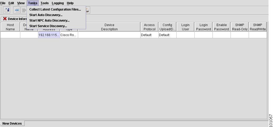
Tasks Menu
From the Inventory Manager Task Bar, shown in Figure 4-25, Tasks is the fourth menu on the Task Bar. The Task menu has the following options:
•
Collect Latest Configuration Files
This option is applied to selected rows in a spreadsheet, if rows are selected. If no rows are selected, all devices contained in the spreadsheet are visited and their configurations are downloaded to the ISC server. It is important for the login and enable passwords to be specified correctly, together with the management address, for each device to be reached and files to be successfully collected.
A persistent task is created on the Master server and Inventory Manager waits for the collection process to complete. When the task completes, you are notified of success or failure. You can use the Web GUI to view the task logs on the Master server to see why a task has failed. If successful, you are prompted to refresh from the Repository. This is recommended, because it is possible that the configuration has changed since the last time the configuration was retrieved.
From the Inventory Manager Task Bar, choose Tasks > Collect Latest Configuration Files to collect the latest configuration files.
Start Auto Discovery
Note
If you do not have existing configuration files, you can discover devices on your network, using the Dynamic Device List.
To create a new Device List and start Auto Discovery, follow these steps:
Step 1
A new Device Spreadsheet appears, as shown in Figure 4-101.
Figure 4-101 New Device Spreadsheet
Step 2
A Management Address window appears, as shown in Figure 4-56.
Figure 4-102 Enter IP Address
Step 3
A Device Information spreadsheet appears, as shown in Figure 4-103.
Step 4
Figure 4-103 Start Device Discovery
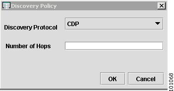
The Discovery Policy window appears, as shown in Figure 4-104.
Figure 4-104 Discovery Policy
Step 5
This number represents the number of hops from the device with the IP address. For example, the number 1.
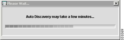
The Please Wait window appears, as shown in Figure 4-105.
Figure 4-105 Please Wait
Note
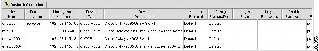
When the waiting period ends, the Device Information spreadsheet appears with the discovered devices, as shown in Figure 4-106.
Figure 4-106 Discovered Devices
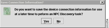
The Save Connection Information window also appears, as shown in Figure 4-107.
Figure 4-107 Save Connection Information
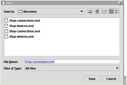
Step 6
A Save Connection Information Confirmation window appears, as shown in Figure 4-108.
Figure 4-108 Save Connection Information Confirmation
Step 7
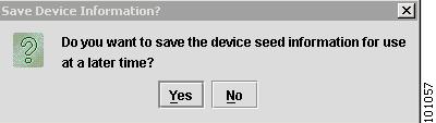
Another Save Device Information window appears, as shown in Figure 4-109.
Figure 4-109 Save Device Information
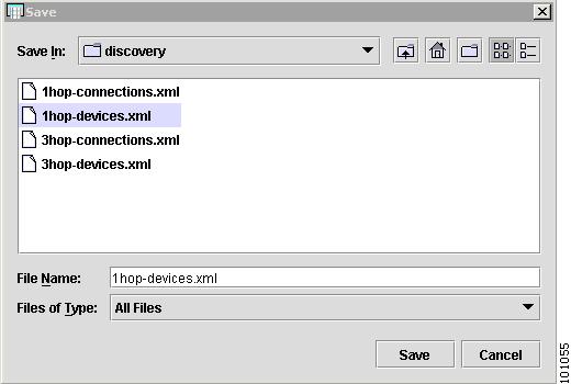
Step 8
The Save Device Information Confirmation window appears, as shown in Figure 4-110.
Figure 4-110 Save Device Information Confirmation
Step 9
The Device Information spreadsheet appears, as shown in Figure 4-111.
Figure 4-111 Device Information
Now you can edit your devices and collect the latest configuration files.
Start NPC Auto Discovery
From the Inventory Manager Task Bar, choose Tasks > Start NPC Auto Discovery to start the connection discovery process.
To import connections with NPC Auto Discovery, follow these steps:
Step 1
You are prompted to provide the path to the correct connection.xml file.
Step 2
A dialog box appears, indicating that the NPC discovery process has started.
Step 3
To find the discovered NPCs, go to Service Inventory > Inventory and Connection Manager > Named Physical Circuits.
Start Service Discovery
To import services with Auto Discovery from Inventory Manager, in the Task Bar choose Tasks > Start Service Discovery to start the service discovery process.
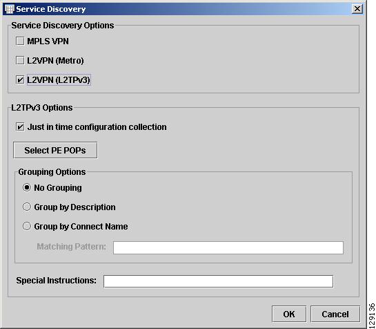
The Service Discovery window in Figure 4-112 appears.
Figure 4-112 Service Discovery
You can choose between the following Service Discovery options:
•
•
•
Note
Checking the L2VPN (L2TPv3) box enables the bottom L2TPv3 Options (see Figure 4-112):
Just in time configuration collection—Upload the PE configurations from the routers
before auto discovery.
Select PEs—Opens the Select PE POPs window, where you can select one or more PE POPs
•
–
–
–
•
You are notified when service discovery is finished.
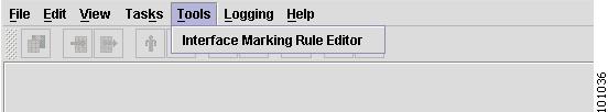
Tools Menu
Note
To open a rule editor where you can create and modify rules for marking interfaces, import and export rule files, and specify values for IPsec, NAT, QoS, and Firewall, choose Tools > Interface Marking Rule Editor from the Inventory Manager Task Bar, as shown in Figure 4-113.
Figure 4-113 Interface Marking Rule Editor
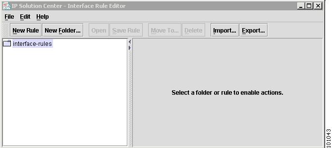
The Interface Rule Editor Task Bar appears with an interface-rules dialog box, as shown in Figure 4-114.
Figure 4-114 Interface Rule Editor Task Bar
The Task Bar has the following options:
•
•
•
File
The File option has the following options:
•
New Rule
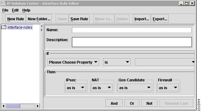
To create a new rule, follow these steps:
Step 1
Figure 4-115 Interface Rule Editor Dialog Box
Step 2
•
•
Step 3
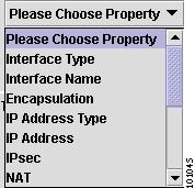
Figure 4-116 Property Drop-Down List
Step 4
Note
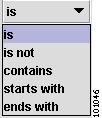
Step 5
Figure 4-117 Relationship Drop-Down List
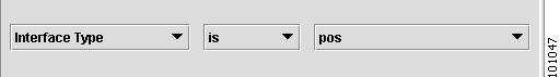
Step 6
Step 7
Figure 4-118 Pos Drop-Down Button
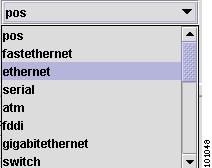
Step 8
Figure 4-119 Type Drop-Down List
Step 9
If you chose ethernet, for example, you would have defined the following interface type If clause in the new rule:
•
You can define how to mark the interface with the Then clause drop-down buttons, as shown in Figure 4-120.
Figure 4-120 Then Clause Drop-Down List
You can create a new rule to mark interfaces for the following security and quality features:
•
•
•
•
Step 10
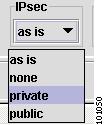
Figure 4-121 IPsec Drop-Down List
Step 11
Step 12
Figure 4-122 NAT Drop-Down List
Step 13
Step 14
Figure 4-123 QoS Drop-Down List
Step 15
Step 16
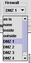
Figure 4-124 Firewall Drop-Down List
Step 17
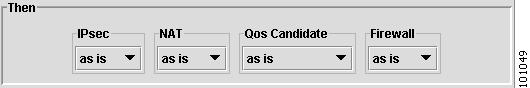
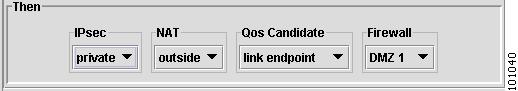
If you selected the security and quality features above, you would have formulated the following Then clause in the new rule:
•
–
–
–
–
The as is for each service shows the changed value in the Then clause drop-down buttons, as shown in Figure 4-125.
Figure 4-125 Then Clause Drop-Down List
You can create additional If clause statements with more complicated logic, by using the And, Or, and Not drop-down buttons, as shown in Figure 4-126.
Figure 4-126 Additional If Clause Drop-Down List
You can remove the additional statements by using the Remove Last button.
Figure 4-127 show an example of a rule with an additional If clause.
Figure 4-127 Example of a Rule
Note
New Folder
Creates a new folder under the selected folder.
Open
Opens the selected rule.
Close
Closes the selected rule.
Import
Imports external rules to an existing folder. Each rule and folder contained in the file is created under the selected folder in the tree.
Export
If you select one or more rules without a folder, the rules are exported to a file of your choice. You can then share this file with other users of Inventory Manager.
If you select a folder, all child folders and contained rules can be exported to a file of your choice. You can then share this file with other users of Inventory Manager.
If used with a single rule, it exports that rule, to a single file.
If used on a folder, it will export all the rules from that folder, to a single file.
Save Rule
Saves the modified rule.
Edit
Delete
Deletes the selected rule or folder.
Moves To
Moves a rule or folder to an existing folder.
Help
About
Contains information on Cisco Systems and the ISC software version.
License
Contains the ISC software license agreement.
Logging Menu
From the Inventory Manager Task Bar, shown in Figure 4-25, Logging is the sixth menu on the Task Bar. The Logging menu allows you to specify the following log output levels to the Logging UI:
•
All log messages are sent to the Log Viewer located near the bottom of Inventory Manager
•
Only severe log messages are sent to the Log Viewer located near the bottom of the Inventory Manager
•
Only warning and severe log messages are sent to the Log Viewer located near the bottom of the Inventory Manager
•
Only informational, warning, and severe log messages are sent to the Log Viewer located near the bottom of the Inventory Manager
•
Only fine, informational, warning, and severe log messages are sent to the Log Viewer located near the bottom of the Inventory Manager
•
Only finer, fine, informational, warning, and severe log messages are sent to the Log Viewer located near the bottom of the Inventory Manager
•
Only finest, finer, fine, informational, warning, and severe log messages are sent to the Log Viewer located near the bottom of the Inventory Manager
•
No log messages are sent to the Log Viewer located near the bottom of the Inventory Manager.
Help
From the Inventory Manager Task Bar, shown in Figure 4-25, Help is the seventh menu on the Task Bar. The Help menu has the following option:
About
Loads the About dialog showing version information and some web URLs for Cisco Systems Inc.
Auto Discovery
This section describes the Auto Discovery features. It contains the following sections:
Auto Discovery Overview
With Auto Discovery, ISC can automatically perform the following operations:
•
•
•
To understand the benefits of Auto Discovery, consider the following business scenario. ISC is connected to a network that contains more than 50 devices with some L2VPN and L3VPN services already provisioned.
Without Auto Discovery, the operator would need to manually enter the following information in ISC:
•
•
Auto Discovery Prerequisites
Before running Auto Discovery, you should do the following:
•
•
•
•
•
Process Flow
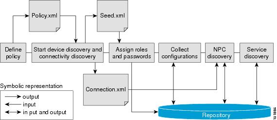
Figure 4-128 shows the Auto Discovery Process.
Figure 4-128 Auto Discovery Process Flow
Cornerstone Bridge Log is available for viewing from an internet browser.
User Interface
There are two user interfaces available for running Auto Discovery:
•
•
Inventory Manager GUI
To use Auto Discovery within Inventory Manager, follow these steps:
Step 1
Step 2
Step 3
Step 4
Step 5
Step 6
Step 7
To see the results of the Auto Discovery and Service Discovery processes, the following screens are available:
•
•
•
UNIX Command Line Interface (UNIX CLI)
To use the UNIX CLI, follow these steps:
Step 1
Step 2
Step 3
Step 4
Step 5
Step 6
Step 7
Service Discovery
This section describes the types of Service Discovery that ISC currently supports. It contains the following sections:
MPLS Service Discovery
This section describes the process for MPLS Service Discovery. This section contains the following sections:
•
•
MPLS Service Discovery Overview
The IP Solution Center (ISC) provides a mechanism to discover the state of the network. Using Inventory Manager, you can discover information about the following network features:
•
•
•
MPLS VPN Service Discovery provides the following benefits:
•
•
An MPLS VPN service request consists of one or more MPLS VPN links. ISC supports Service Discovery for two types of MPLS VPN links:
•
•
The Unmanaged CE option is also supported for the PE-CE type.
Limitations
In cases where Auto Discovery is used, ISC has the following Auto Discovery limitations:
•
•
MPLS Service Discovery Process
The MPLS Service Discovery process creates one MPLS VPN Service Request for each VRF-enabled interface. A VRF-enabled interface is an interface on which the ip vrf forwarding command is configured on the PE.
Note
The following steps describe the logic MPLS Service Discovery uses to create Service Requests and populate the Repository:
Step 1
Step 2
Step 3
Step 4
Step 5
Otherwise, for each VRF-enabled interface, find the CE connected to the interface in the Named Physical Circuit (NPC) table, which was populated by the NPC Discovery process.
Note
Step 6
Step 7
Step 8
Note
Step 9
Step 10
Note
Step 11
Step 12
Step 13
Step 14
Step 15
Synchronization
The MPLS Service Discovery process does not synchronize existing services. If it is determined that an SR exists in the Repository for a particular interface, the Discovery process ignores the interface. But, if you have manually added a service on a new interface and ISC is not aware of it, the Service Discovery process creates the newly added service in the Repository.
CERC Creation
Given a list of Route Targets in the configuration files for each of the VRFs, the MPLS VPN Service Discovery module needs to re-create the CERC according to the ISC service model. MPLS VPN Service Discovery assumes that the services provisioned on the network are provisioned manually and do not follow the conventions adopted by ISC for topologies (CERC Route Target Allocation). As a result, a CERC created to fit into the service model supported by ISC is not associated with any VPN. You must create the VPN and associate it to the CERC created by discovery.
User Input After Discovery
After Service Discovery, a Policy and an SR are created. When a CE is discovered, a Customer-owned Policy is created. When no CE is discovered, a Provider-owned Policy and Global SR are created. After the Service Discovery process is complete, you cannot modify the relationship between the Customer and the SR. This restriction applies to both the Customer-owned and Global SRs.
The Service Discovery process ends with the newly created Service Requests in a PENDING state and the related objects in the Repository. After the completion of the Discovery process, you must go to the GUI, create the VPN, and connect the VPN with the CERC.
You cannot modify the Policy or the SR or associate an SR with a Customer or Provider at this point.
Because the CERC is a logical concept used within ISC to represent topologies, Service Discovery is unable to connect the way you have manually configured the services with CERC.
Note
Grey Management Discovery
This section describes the process of Grey Management Discovery.
The following steps describe the logic MPLS Service Discovery uses to create Grey Management Service Requests and populate the Repository:
Step 1
Step 2
Step 3
The discovery process also caches the route target of the Management VRF.
Step 4
Step 5
Layer 2 VPN Discovery
This section contains the following sections:
Topology
L2 VPN Discovery:
•
•
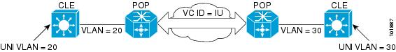
Figure 4-129 shows the L2VPN Discovery Topology.
Figure 4-129 L2VPN Discovery Topology
Logic (MPLS Core)
The following steps describe the logic that L2VPN Service Discovery uses to create Service Requests and populate the Repository for an MPLS core:
Step 1
Step 2
Step 3
Step 4
Step 5
Logic (L2TPv3)
L2TPv3 service discovery can be performed from Inventory Manager as described in Start Service Discovery.
In the case of L2TPv3, the L2VPN Service Discovery uses the following steps to create Service Requests and populate the Repository:
Step 1
Step 2
Step 3
VPLS Service Discovery
This section contains the following sections:
Topology
VPLS Discovery:
•
•
•
Figure 4-130 shows an MPLS core topology to help demonstrate how VPLS Service Discovery creates an SR and associates it with a VPN link.
Figure 4-130 MPLS Network
Logic
The following steps describe the logic L2VPN Service Discovery uses to create Service Requests and populate the Repository:
Step 1
Step 2
Restrictions
Due to the existing VPLS Policy Types, VPLS Discovery has the following limitations:
•
•
•
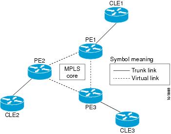
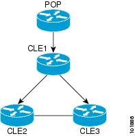
Ring Topology Discovery (Connection Discovery)
Connection Discovery can discover ring topology NPCs. A ring of NPCs is a group of physical links that form a loop between the logical CLE devices.
Figure 4-131 shows an sample ring topology.
Figure 4-131 Sample Ring Topology