-
Cisco IP Solution Center Infrastructure Reference, 4.0
-
Index
-
About This Guide
-
Getting Started
-
WatchDog Commands
-
Service Inventory > Inventory and Connection Manager
-
Service Inventory > Inventory and Connection Manager > Inventory Manager
-
Service Inventory > Device Console
-
Service Design
-
Monitoring
-
Administration
-
Cisco CNS IE2100 Appliances
-
Property Settings
-
Glossary
-
 Feedback
Table Of Contents
Administration
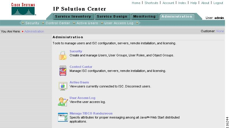
From the Home window of Cisco IP Solution Center (ISC), you receive upon logging in, click the Administration tab and you receive a window as shown in Figure 8-1, "Administration Selections."
Figure 8-1 Administration Selections
Then you can navigate to the following selections:
•
Security Create and manage Users, User Groups, User Roles, and Object Groups
•
•
•
•
Security
This section describes how system administrators create, edit, and delete users, user groups, and user roles and how privileges are assigned to these entities.
The security features are only accessible to the user admin or users with the following roles:
•
•
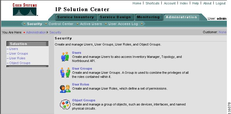
Navigate Administration > Security to access the user management tools. The window shown in Figure 8-2, "Security Window," appears.
Figure 8-2 Security Window
From the Security window, navigate to the following:
•
•
•
•
For an example of how to use the Users, User Groups, User Roles, and Object Groups, see the "User Roles Design Example" section.
Users
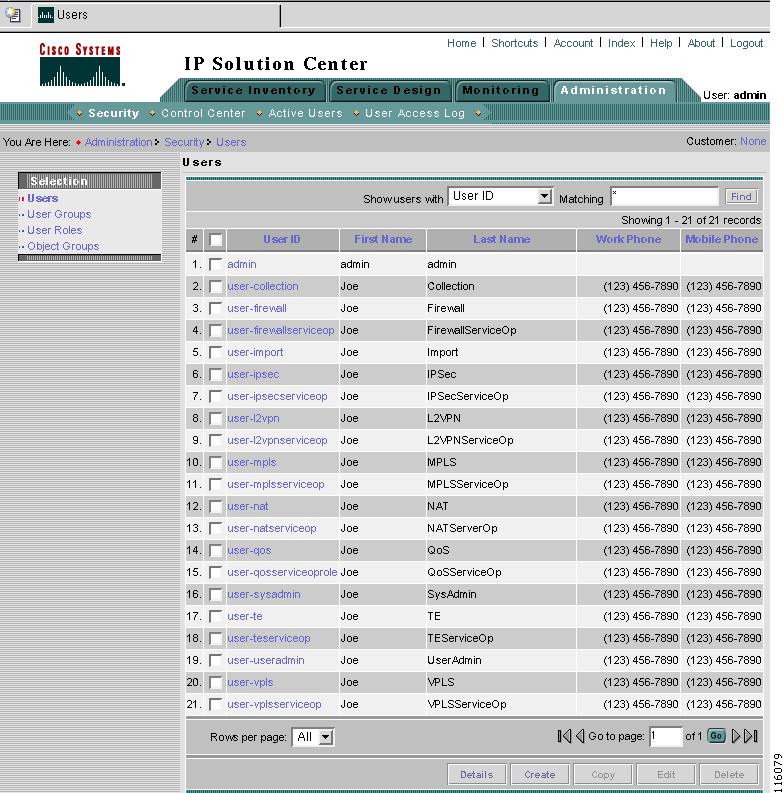
Navigate Administration > Security > Users and follow these steps:
Step 1
Figure 8-3 Users Window
Step 2
•
•
•
•
•
Enter the search criteria, using * if you want, and click Find.
Note
Step 3
Step 4
•
•
•
•
•
Details
The Details button, located at the bottom of Figure 8-3, has the following columns of information: User ID; User Group that a user belongs to; Role that a user occupies; Resource Privilege permissions that a user has for each role occupied; Object Group that a user role is associated with; Customer View that a user's role is limited to; Provider View that a user's role is limited to. Navigate Administration > Security > Users and click the Details button.
Create
The Create button, located at the bottom of Figure 8-3, allows a user with the required privileges to create a new user. Follow these steps:
Step 1
Step 2
Figure 8-4 Create/Edit Users Window
Step 3
•
•
•
•
•
A user's group membership can also be changed in the group editor (see the "Edit" section).
•
The user inherits all the privileges from the groups in which it participates and from the roles assigned to it. That is, the permissions received by the user is an OR result of the permissions in each role.
Step 4
•
•
•
•
•
•
•
Step 5
•
•
•
•
Step 6
Copy
The Copy button, located at the bottom of Figure 8-3, provides a convenient way to create a new User by copying the information for an existing User including User Groups, Assigned Roles, and User Preferences. Follow these steps:
Step 1
Step 2
Step 3
Step 4
Step 5
Step 6
Edit
The Edit button, located at the bottom of Figure 8-3, allows a user with the required privileges to edit user-specific information. Follow these steps:
Step 1
Step 2
Step 3
Note
Step 4
Step 5
Delete
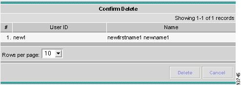
The Delete button, located at the bottom of Figure 8-3, allows a user with the required privileges to delete user-specific information. Follow these steps:
Step 1
Step 2
Step 3
Figure 8-5 Users Confirm Delete
Step 4
Step 5
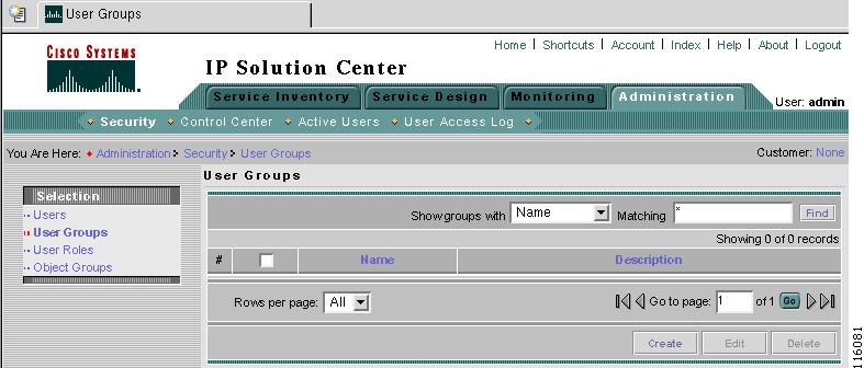
User Groups
A user group is a logical grouping of users with common privileges. The User Groups feature is used to create, edit, or delete user groups.
To access the User Groups window, navigate Administration > Security > User Groups and follow these steps:
Step 1
Figure 8-6 User Groups Window
Step 2
•
•
Enter the search criteria, using * if you want, and click Find.
Note
Step 3
Step 4
•
•
•
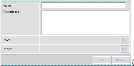
Create
The Create button, located at the bottom of Figure 8-6, allows a user with the required privileges to create a user group. Follow these steps:
Step 1
Step 2
Figure 8-7 Create/Edit User Groups Window
Step 3
•
•
•
•
Step 4
Edit
The Edit button, located at the bottom of Figure 8-6, allows a user with the required privileges to edit user group-specific information. Follow these steps:
Step 1
Step 2
Step 3
Step 4
Step 5
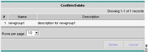
Delete
The Delete button, located at the bottom of Figure 8-6, allows a user with the required privileges to delete user group-specific information. Follow these steps:
Step 1
Step 2
Step 3
Figure 8-8 User Groups Confirm Delete
Step 4
Step 5
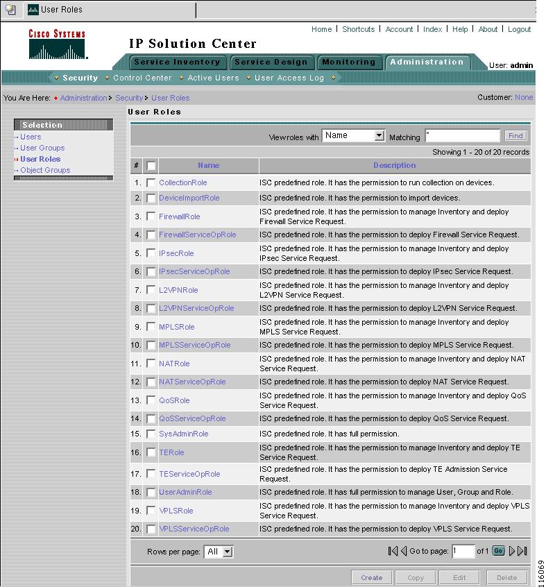
User Roles
A user role is a predefined or a user-specified role defining a set of permissions. The User Roles feature is used to create, edit, or delete user roles.
To better understand the way roles are managed, certain specific characteristics of roles are defined as follows:
•
•
•
Customer view and provider view within a role have no affect on those objects that do not belong to either a customer or a provider. Those object types are: task, probe, workflow, device, ISC host, and template.
Permission operation types in a Role editor, namely View, Create, Edit, and Delete mean View, Create, Modify, and Delete on database object. For example, SR modification (or subsumption) is viewed as Role Based Access Control (RBAC) Creation. SR purge is viewed as RBAC Delete.
A Role can be enabled to be associated with Object Group(s). When Object Group association is enabled, a Role can no longer be associated with a Customer or a Provider, and it cannot have a Parent Role. Resources are limited to PE, CPE, and Named Physical Circuit only. PE and CPE permission implies Device Permission.
Note
Separate provider-view from customer-view roles when defining a role. When a role is associated with a provider, choose only the resources for which an access scope can be constrained by a provider view. Do the same for a customer-view role.To access the User Roles window, navigate Administration > Security > User Roles and follow these steps:
Step 1
Figure 8-9 User Roles Window
The predefined roles shown in Figure 8-9 are provided with associated permissions that cannot be edited or deleted. They are intended to cover most of the needed use cases to facilitate a rapid assignment of roles to users and groups with minimum manual configuration. They can also be used as examples to create new roles.
Step 2
•
•
Enter the search criteria, using * if you want, and click Find.
Note
Step 3
Step 4
•
•
•
•
Create
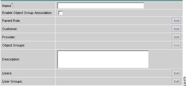
The Create button, located at the bottom of Figure 8-9, allows a user with the required privileges to create a new user role. Follow these steps:
Step 1
Step 2
Figure 8-10 Create/Edit User Roles Window (Top)
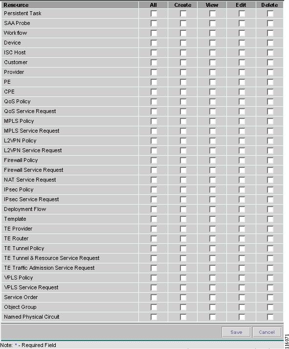
Figure 8-11 Create/Edit User Roles Window (Bottom)
Step 3
•
•
•
•
Note
•
•
•
•
Note
•
Step 4
Note
Note
Note
Step 5
Copy
The Copy button, located at the bottom of Figure 8-9, provides a convenient way to copy the information from an existing User Role and edit it to create a new User Role. Follow these steps:
Note
Step 1
Step 2
Step 3
Step 4
Step 5
Step 6
Edit
The Edit button, located at the bottom of Figure 8-9, allows a user with the required privileges to edit user role-specific information. Follow these steps:
Step 1
Step 2
Step 3
Step 4
Step 5
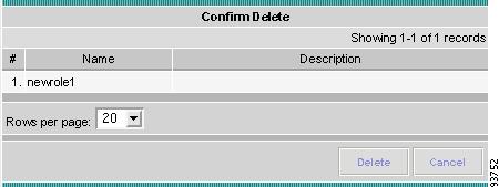
Delete
The Delete button, located at the bottom of Figure 8-9, allows a user with the required privileges to delete user role-specific information. Follow these steps:
Step 1
Step 2
Step 3
Figure 8-12 User Roles Confirm Delete
Step 4
Step 5
Object Groups
An Object Group is a named aggregate entity comprised of a set of objects. The object types can be PE, CE, Named Physical Circuit (NPC), and interfaces of PEs or CEs. An Object Group provides instance level of access granularity for users.
An Object Group can be associated with different roles. A role can be associated with multiple Object Groups. A role can be associated with either Object Group(s), or a Customer, a Provider, but not both. When a role is associated with Object Group(s), you can only define permissions for PE, CE, and NPC. Permissions on interfaces is implied PEs or CEs, that is, PE Create or CE Create implies Interface Create. PE or CE Edit implies Interface Create, Edit, or Delete. CE or PE Delete implies Interface Delete.
When instance level of access is desired for PE, CE, NPC, or interface of PEs and CEs, you can usually define a role associated with Object Group(s) that contains a collection of PEs and CEs that you are limited to operate. Then define other roles to include permissions on other types of objects. See the "User Roles Design Example" section.
If an Object Group contains PEs (or CEs) only, with no explicit interface as a group member, you can access all interfaces of grouped PEs or CEs. If an Object Group contains any explicit interface as group members, every single interface that you want to access you must manually choose to include as group members.
Note
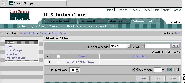
To access the Object Groups window, navigate Administration > Security > Object Groups and follow these steps:
Step 1
Figure 8-13 Object Groups Window
Step 2
•
•
Enter the search criteria in Matching, using * if you want, and click Find.
Note
Step 3
Step 4
•
•
•
Create
The Create button, located at the bottom of Figure 8-13, allows a user with the required privileges to create a new object group. Follow these steps:
Step 1
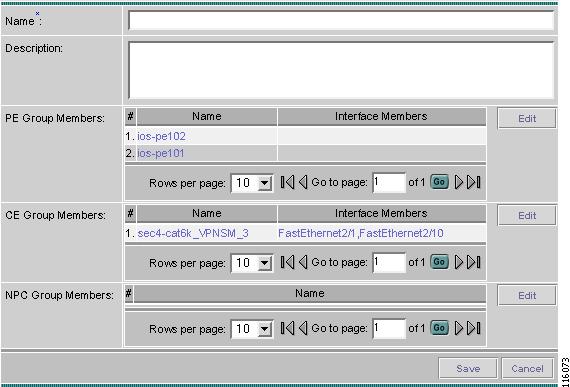
Step 2
Figure 8-14 Create/Edit Object Group Window
Step 3
•
•
•
•
•
Step 4
Edit
The Edit button, located at the bottom of Figure 8-14, allows a user with the required privileges to edit object group-specific information. Follow these steps:
Step 1
Step 2
Step 3
Step 4
Step 5
Delete
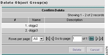
The Delete button, located at the bottom of Figure 8-14, allows a user with the required privileges to delete object group-specific information. Follow these steps:
Step 1
Step 2
Step 3
Figure 8-15 Delete Object Groups Confirm Delete
Step 4
Step 5
User Roles Design Example
This section gives an example situation, an illustration that shows this setup, and steps on how to setup this design:
Example
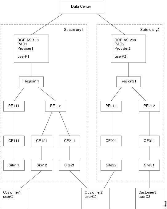
This section explains an example data center for which the following sections, "Illustration of Setup" section and "Steps to Set Up Example" section give an illustration setup and steps, respectively.
Finance Customer XYZ built an MPLS network to connect its branch offices to its data center. Subsidiaries of XYZ are running different parts of the MPLS network. Each subsidiary uses a different BGP AS domain, which results in different Provider Administrative Domains (PADs) inside ISC.
Each subsidiary acts as a Provider and owns therefore its own Devices, like PE and CE devices and should also own logical attributes inside ISC, like Regions, Sites, Customers, and VPNs. Therefore, the view of the devices for each subsidiary must be separated into PAD views. Thus, Provider A cannot manipulate or view the configuration files for devices of Provider B. Devices are not shared between PADs.
Inside a PAD, there are Customers with sites and VPNs with only local significance. Also, the IP addressing should be defined per PAD.
But there are also Customers that have sites in different PADs. This means that there is a need for Inter-AS VPNs. The Provider who owns the Customer should also have the right to share this Customer with other Providers. In this case, the VPNs and CERCs should be shared between the providers.
Illustration of Setup
Figure 8-16, "Contents in Example," shows the setup described in the "Example" section.
Figure 8-16 Contents in Example
Steps to Set Up Example
This section explains the steps to create the example explained in the "Example" section and shown in the "Illustration of Setup" section.
Step 1
•
•
•
•
•
•
•
Step 2
•
•
•
•
•
Step 3
•
•
•
•
•
Step 4
•
•
•
•
•
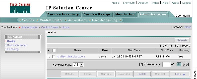
Control Center
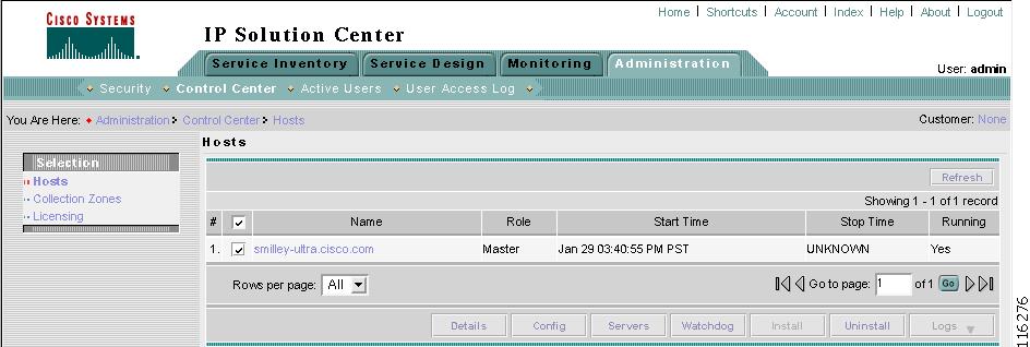
This section explains how to view and change the properties in the Dynamic Component Properties Library (DCPL); how to view status information about a host, servers, the WatchDog, and logs; how to remotely install and uninstall a Processing server, Collection server, or Interface server; how to define collection zones; and how to install license keys.
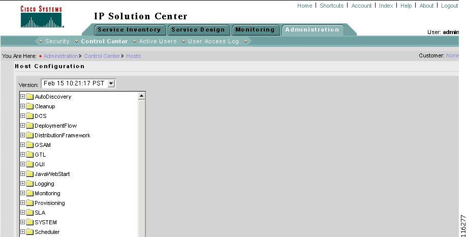
Navigate Administration > Control Center and you go to the default page of Hosts in the TOC, as shown in Figure 8-17, "Control Center > Hosts."
Figure 8-17 Control Center > Hosts
From Administration > Control Center, you have the following three choices in the TOC:
•
•
•
Hosts
Navigate Administration > Control Center > Hosts.
A window as shown in Figure 8-17 appears.
Note
Click any of the buttons and proceed as follows:
•
•
•
•
•
•
•
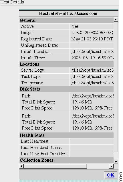
Details
For details about a chosen host, do the following:
Step 1
Step 2
Figure 8-18 Host Details
Step 3
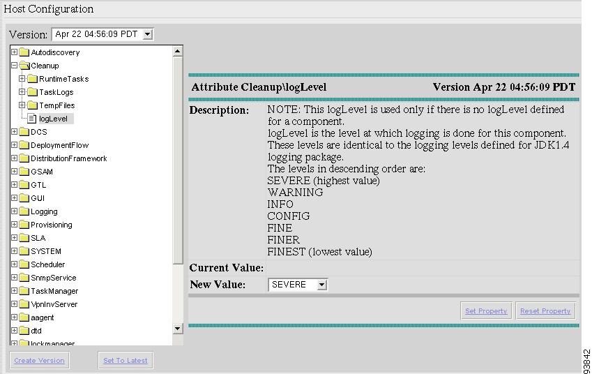
Config
To view or change the Dynamic Component Properties Library (DCPL) properties, which replaces the csm.properties file for VPNSC, do the following:
Note
Step 1
Step 2
Figure 8-19 Properties
Step 3
Step 4
Step 5
Figure 8-20 Properties Detail Example
Step 6
Step 7
Step 8
Step 9
Step 10
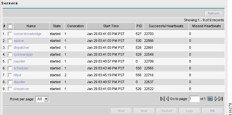
Servers
To view the status information about the servers, do the following:
Step 1
Step 2
Figure 8-21 Servers
Step 3
Step 4
Step 5
Watchdog
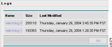
To view the log information about WatchDog, do the following:
Step 1
Step 2
Figure 8-22 WatchDog Logs
Step 3
Step 4
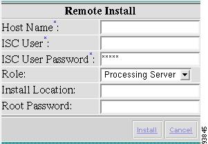
Install
You can remotely install the Processing Server, Collection Server, or Interface Server, as follows:
Note
Note
Step 1
Step 2
Figure 8-23 Remote Install
Step 3
•
•
Note
•
•
•
•
Step 4
Step 5
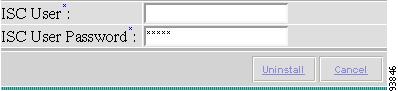
Uninstall
You can remotely uninstall the Processing Server, Collection Server, or Interface Server, as follows:
Step 1
Step 2
Figure 8-24 Remote Uninstall
Step 3
•
•
Step 4
Step 5
Logs
You can view install and uninstall logs for the Master and remotely installed server, as follows:
Step 1
Step 2
Step 3
Step 4
Step 5
Step 6
Collection Zones
Navigate Administration > Control Center.
A collection zone is a geographical grouping of devices. Each collection zone is associated with exactly one Collection server that collects data from its devices. However, a Collection server can service multiple collection zones. For example, if you initially create several collection zones and have them all serviced by the Master server, then as the number of devices in each zone grows, you can install additional Collection servers and assign some of the zones to them.
When you install a new Collection server or Processing server, the system creates a new collection zone with the same name as the server. This functionality is for your convenience. You can delete this collection zone if this does not fit your distribution environment setup.
To define collection zones, do the following:
Step 1
Figure 8-25 Choose Control Center > Collection Zones
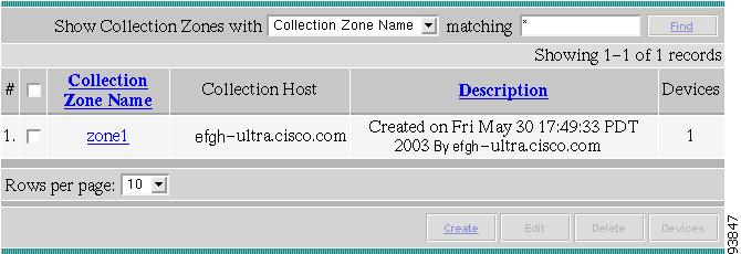
Step 2
Figure 8-26 Collection Zones
Step 3
Step 4
Step 5
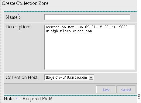
Figure 8-27 Create Collection Zone
Fill in the following information:
•
•
•
Step 6
Step 7
Step 8
Step 9
Step 10
Step 11
Step 12
Step 13
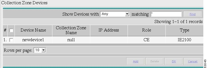
Figure 8-28 Collection Zone Devices
Step 14
Step 15
Step 16
Step 17
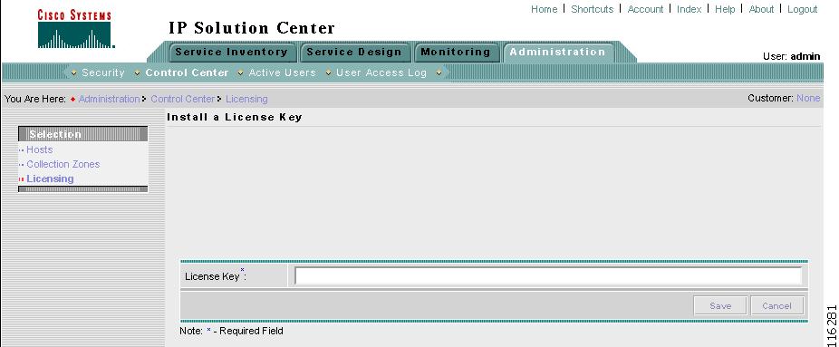
Licensing
Navigate Administration > Control Center.
Note
system.propertiesTo install license keys, do the following:
Step 1
Figure 8-29 Choose Control Center > Licensing
Step 2
Note
Note
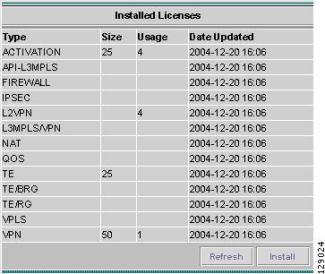
Figure 8-30 Install Button
Step 3
Figure 8-31 Enter License Key
Step 4
Step 5
Note
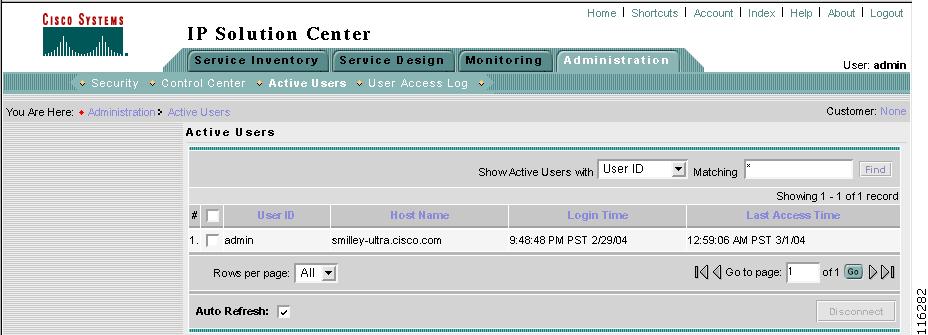
Active Users
This section explains how to communicate with active users.
Navigate Administration > Active Users and follow these steps:
Step 1
Figure 8-32 Active Users
Step 2
Caution
Step 3
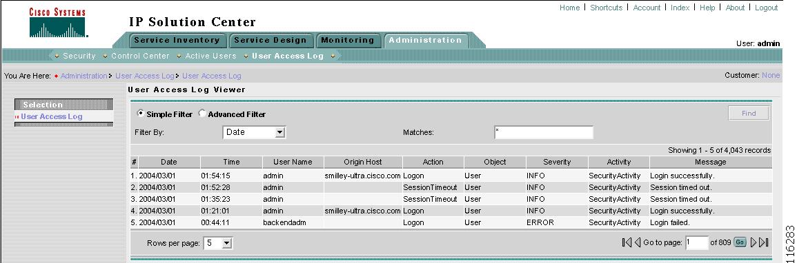
User Access Log
This section shows a detailed report of every activity by every user.
Navigate Administration > User Access Log and follow these steps:
Step 1
Figure 8-33 User Access Log Viewer with Simple Filter
All the log information about user actions appears.
Note
Step 2
Step 3
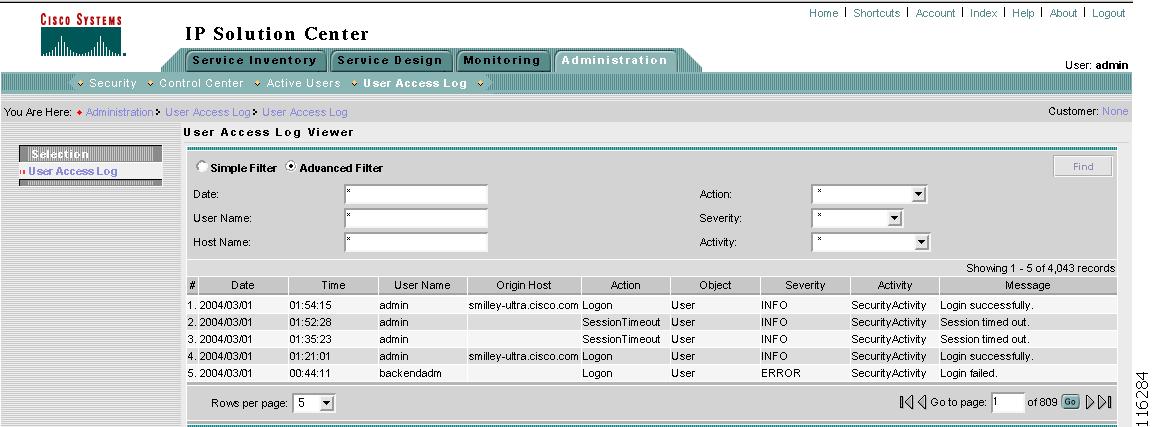
Step 4
Step 5
Figure 8-34 User Access Log Viewer with Advanced Filter
All the log information about user actions appears.
Step 6
Note
•
•
•
•
•
•
Step 7
Manage TIBCO Rendezvous
The only reason you would ever use this functionality is if you change the TIBCO ports for TIBCO Rendezvous Agent (rva) or TIBCO Rendezvous Daemon (rvd) after installation. The changes being made here only affect Java WebStart applications, such as Inventory Manager and the topology tool.
Navigate Administration > Manage TIBCO Rendezvous and follow these steps:
Step 1
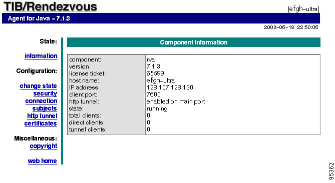
Figure 8-35 TIBCO Rendezvous
Step 2
Step 3
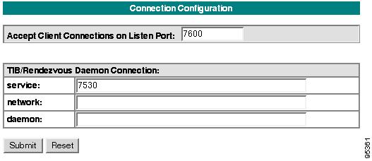
Figure 8-36 Connection Configuration
If you must change the rva port number from the existing value, change the Accept Client Connections on Listen Port: field to your new rva port number for ISC. If you must change the rvd port number from the existing value, change the service field to your new rvd port number for ISC. Then click Submit. Then Figure 8-36 returns with the new value and a note that says "Configuration change will take effect after RVA is re-activated. To re-activate RVA set it into idle state and then back to active state."
Step 4
Step 5
Step 6
•
•
Step 7
Step 8