-
Cisco IP Solution Center Infrastructure Reference, 4.0
-
Index
-
About This Guide
-
Getting Started
-
WatchDog Commands
-
Service Inventory > Inventory and Connection Manager
-
Service Inventory > Inventory and Connection Manager > Inventory Manager
-
Service Inventory > Device Console
-
Service Design
-
Monitoring
-
Administration
-
Cisco CNS IE2100 Appliances
-
Property Settings
-
Glossary
-
 Feedback
Table Of Contents
View Templates Tree and Data Pane
Summary of Repository Variables
Service Design
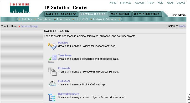
From the Home window of Cisco IP Solution Center (ISC), you receive upon logging in, click the Service Design tab and you receive a window as shown in Figure 6-1, "Service Design Selections."
Figure 6-1 Service Design Selections
Next you can navigate to the following selections:
•
Policies Create and manage Policies for licensed services.
•
•
•
•
Policies
Policies is explained in each of the User Guides for each of the licensed services.
Templates
Templates supports the browsing, creation, and deletion of Template Folders, Templates, and Data Files as well as the viewing of Template-generated configurations. The configuration created from the template and data file can be downloaded to devices. When creating a Service Request, you can select from the list of templates and data files and associate them with the Service Request. At Deploy time, the template and data file are instantiated and the configuration is appended or prepended to the configlet generated by ISC.
ISC provides a way to integrate a template with ISC configlets.
For a given customer edge router, you specify the following:
•
•
•
•
The template data files are tightly linked with the corresponding template. You can use a data file and its associated template to create a template configuration file. The template configuration file is merged with (either appended or prepended to) the ISC configlet. ISC downloads the combined ISC configlet and template configuration file to the edge device router.
•
•
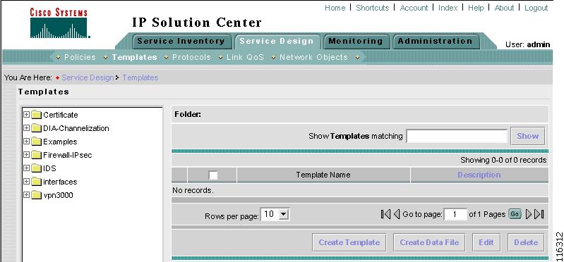
To use Templates, do the following:
Step 1
Figure 6-2 Templates
Template examples are shown in the left column. A complete list of template examples is specified in the "Template Examples" section. A complete list of Repository variables is shown in the "Summary of Repository Variables" section.
Step 2
•
•
•
View Templates Tree and Data Pane
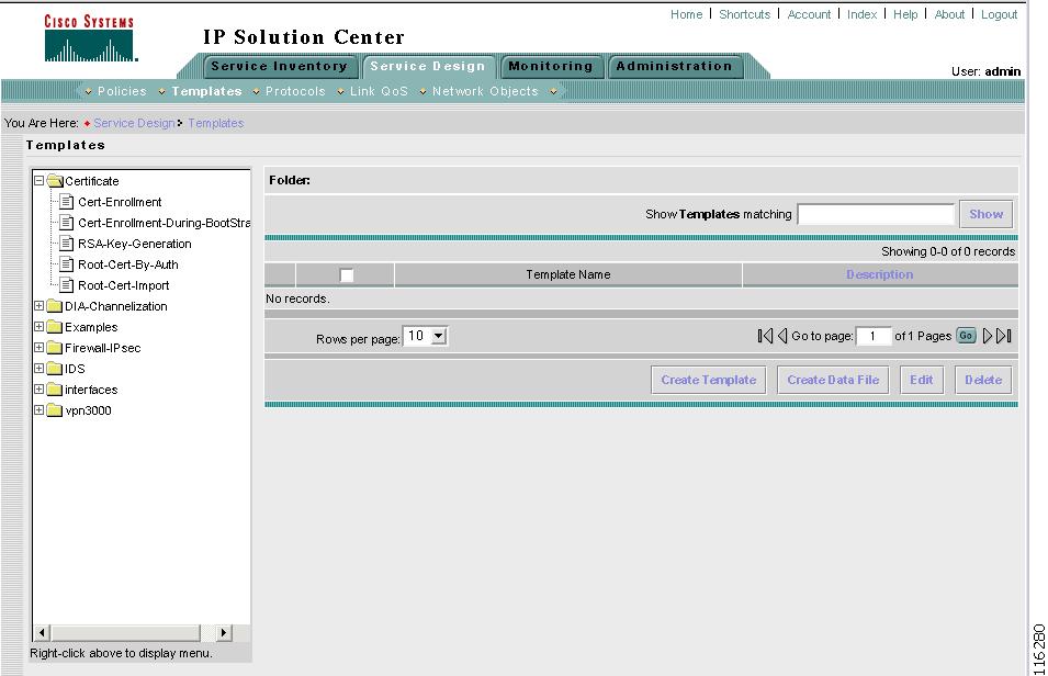
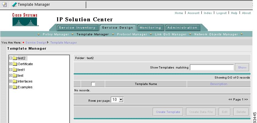
When you navigate to Service Design > Templates, you receive a window as shown in Figure 6-3, "Tree and Data Pane Structure."
The Templates tree is in the left column. You can continue clicking the + sign next to each created folder and subfolder until you get to the last level of information. The last possible level is the template name. Data file information is not kept in the tree.
The right section of the window is the data pane. The name of the folder or template is in the upper-left corner. When you select the check box next to the template or data file information, the Create Template, Create Data File, Edit, or Delete buttons are enabled as described in the following sections.
When there are many templates in a folder or many data files in a template, the Show Template Matching or Show Data File Matching filter in the upper right hand corner of the data pane can be very useful. For example, you might just want to work with templates or data files that start with abc. In this case, enter abc* in the field and then click the Show button. Only the templates or data files that start with abc appear.
You can also View configurations when the table displays data files.
Figure 6-3 Tree and Data Pane Structure
Create Folders and Subfolders
To create a new folder or subfolder, do the following:
Step 1
Step 2
Note
Step 3
Figure 6-4 Folder Naming
Copying Folders or Subfolders
You can copy a folder or subfolder and paste it into another folder or subfolder, as follows:
Step 1
Step 2
Step 3
Create Template
You can either create a new template in an existing folder or you can create a new folder first and then create the template. To create a new folder, see the section "Create Folders and Subfolders".
To create a new template, do the following:
Step 1
Step 2
Step 3
Figure 6-5 Folder with Existing Templates
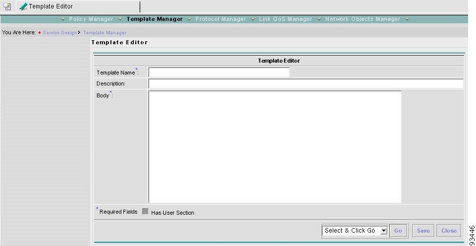
Step 4
Figure 6-6 Template Editor
Step 5
•
•
•
Note
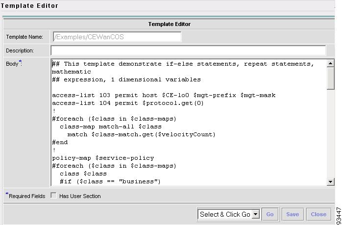
An example template is shown in Figure 6-7, "Example Template."
Figure 6-7 Example Template
ISC has the template system predefined variable $TMSystem that can be used within the template body text to access template system functions. The syntax is as follows, where, $ipAddrMask is a string that contains an IP address and its mask in the format of: 10.33.4.5/30:
$TMSystem.getAddr ($ipAddrMask) returns: 10.33.4.5
$TMSystem.getMask ($ipAddrMask) returns: 255.255.255.252
$TMSystem.getReverseMask ($ipAddrMask) returns: 0.0.0.3
$TMSystem.getNetworkAddr ($ipAddrMask) returns: 10.33.4.4
$TMSystem.getClassfulNetworkAddr ($ipAddrMask) returns: 10.0.0.0
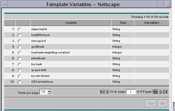
Step 6
Figure 6-8 Template Variables
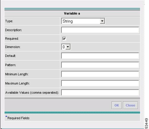
Step 7
Figure 6-9 Variable Definition—Type String
Step 8
•
•
•
•
•
•
•
Step 9
•
•
•
•
•
•
•
•
After you enter all the data, click OK to accept this information for the specified variable; continue editing all variables you want to change in this same way, then click OK in a window such as Figure 6-8, which now includes these updated variables; click Save and then Close or click Close and when asked, agree to Save for a window such as Figure 6-6. Create a Data File is shown in the "Create Data File" section, Edit is shown in the "Edit" section, and Delete is shown in the "Delete" section.
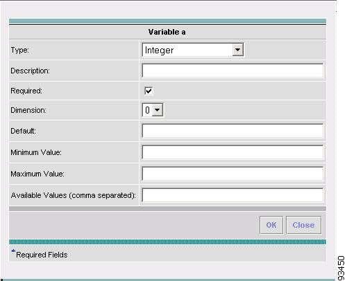
Step 10
•
•
•
•
•
•
•
After you enter all the data, click OK to accept this information for the specified variable; continue editing all variables you want to change in this same way, then click OK in a window such as Figure 6-8, which now includes these updated variables; click Save and then Close or click Close and when asked, agree to Save for a window such as Figure 6-6. Create a Data File is shown in the "Create Data File" section, Edit is shown in the "Edit" section, and Delete is shown in the "Delete" section.
Figure 6-10 Variable Definition—Type Integer
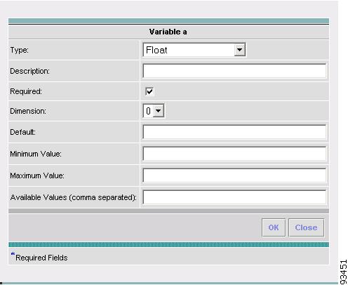
Step 11
•
•
•
•
•
•
•
After you enter all the data, click OK to accept this information for the specified variable; continue editing all variables you want to change in this same way, then click OK in a window such as Figure 6-8, which now includes these updated variables; click Save and then Close or click Close and when asked, agree to Save for a window such as Figure 6-6. Create a Data File is shown in the "Create Data File" section, Edit is shown in the "Edit" section, and Delete is shown in the "Delete" section.
Figure 6-11 Variable Definition—Type Float
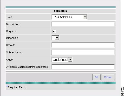
Step 12
•
•
•
•
•
•
•
After you enter all the data, click OK to accept this information for the specified variable; continue editing all variables you want to change in this same way, then click OK in a window such as Figure 6-8, which now includes these updated variables; click Save and then Close or click Close and when asked, agree to Save for a window such as Figure 6-6. Create a Data File is shown in the "Create Data File" section, Edit is shown in the "Edit" section, and Delete is shown in the "Delete" section.
Figure 6-12 Variable Definition—Type IPv4
Step 13
•
•
•
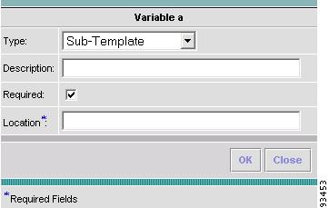
The variable varName is defined as the subtemplate type (by selecting Variables and clicking Go). The Sub-Template defined earlier is called and you must provide the subtemplate path. The syntax is as follows:
$<varName>.callWithDatafile (<DatafileName>)
After you enter all the data, click OK to accept this information for the specified variable; continue editing all variables you want to change in this same way, then click OK in a window such as Figure 6-8, which now includes these updated variables; click Save and then Close or click Close and when asked, agree to Save for a window such as Figure 6-6. Create a Data File is shown in the "Create Data File" section, Edit is shown in the "Edit" section, and Delete is shown in the "Delete" section.
Figure 6-13 Variable Definition—Type Sub-Template
Step 14
•
•
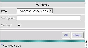
The variable varName is defined as the Dynamic Java Class type (by selecting Variables and clicking Go). The syntax is as follows:
$<varName>.<method_name_in_Java_class> ([<parameters>])
After you enter all the data, click OK to accept this information for the specified variable; continue editing all variables you want to change in this same way, then click OK in a window such as Figure 6-8, which now includes these updated variables; click Save and then Close or click Close and when asked, agree to Save for a window such as Figure 6-6. Create a Data File is shown in the "Create Data File" section, Edit is shown in the "Edit" section, and Delete is shown in the "Delete" section.
Figure 6-14 Variable Definition—Type Dynamic Java Class
Step 15
•
•
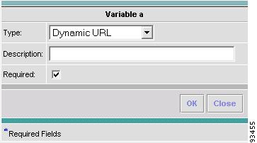
The variable varName is defined as the Dynamic URL type (by selecting Variables and clicking Go). The syntax is as follows:
$<varName>.callURL (<url-address>)
After you enter all the data, click OK to accept this information for the specified variable; continue editing all variables you want to change in this same way, then click OK in a window such as Figure 6-8, which now includes these updated variables; click Save and then Close or click Close and when asked, agree to Save for a window such as Figure 6-6. Create a Data File is shown in the "Create Data File" section, Edit is shown in the "Edit" section, and Delete is shown in the "Delete" section.
Figure 6-15 Variable Definition—Type Dynamic URL
Copying Templates
You can copy a template and paste it into another folder, as follows:
Step 1
Step 2
Step 3
Create Data File
You can create a new data file from an existing template. If the template you want is not available, go to the "Create Template" section.
To create a data file, do the following:
Step 1
Step 2
1.
2.
Step 3
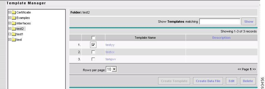
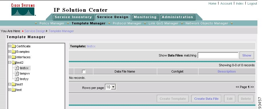
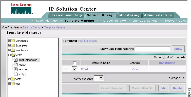
Figure 6-16 Choose Existing Template > Create Data File
Select the check box for the template for which you want to create a data file and click Create Data File. Then proceed to Step 5.
Otherwise, proceed to Step 4.
Step 4
Figure 6-17 Choose Existing Template > Create Data File
Click Create Data File and proceed to Step 5.
Step 5
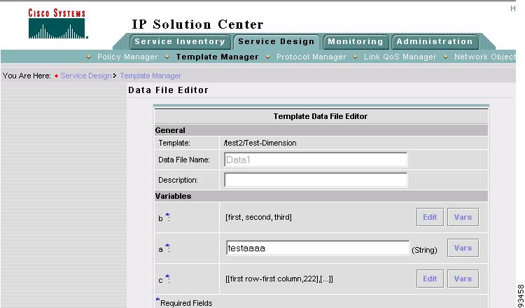
Figure 6-18 Template Data File Editor
Step 6
•
•
Step 7
If a is a Dynamic Java Class variable, you must enter the entire Java Class package name. For example: com.cisco.isc.class_name.
Step 8
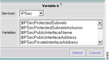
Figure 6-19 Template Data File Editor
Click the Services drop-down menu to have access to variables for:
•
•
•
•
•
Then click the entry in Variables that you want to use and click Select.
If you have a 0 dimensional entry (set as Dimension 0 when creating a template), you can only enter variables in the provided field.
Step 9
Proceed to Step 10 for information about a 1 dimensional array.
Proceed to Step 13 for information about a 2 dimensional array.
Step 10
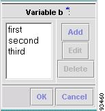
Figure 6-20 Editing a One-Dimensional Array
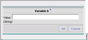
Step 11
Figure 6-21 Adding a Variable
Step 12
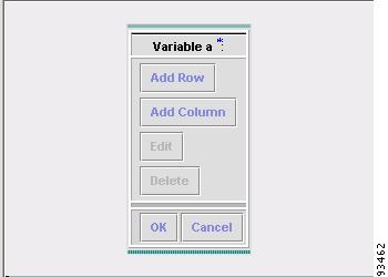
Step 13
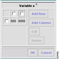
Figure 6-22 Editing a Two-Dimensional Array
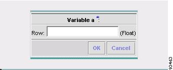
Step 14
Figure 6-23 Enter Row Information
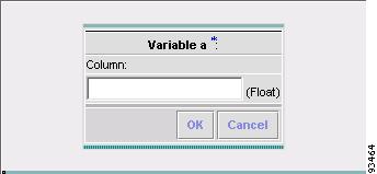
Step 15
Figure 6-24 Enter Column Information
Step 16
Figure 6-25 Two-Dimensional Array Results
Step 17
Step 18
Step 19
Step 20
Edit
To edit a Template or Data File, do the following:
Step 1
Step 2
Step 3
Figure 6-26 Choose Existing Template > Edit
Figure 6-27 Choose Existing Data File > Edit
Step 4
Note
Step 5
Step 6
Delete
To delete a Template or Data File, do the following:
Step 1
Step 2
Step 3
Figure 6-28 Choose Existing Template > Delete
Figure 6-29 Choose Existing Data File > Delete
Step 4
Note
Step 5
Step 6
Template Examples
In the left column, the hierarchy pane, of Service Design > Templates, as shown in Figure 6-2, "Templates," template examples appear. See Table 6-1, "Template Examples and Their Descriptions."
Summary of Repository Variables
This section contains the following tables:
•
•
•
•
•
•
•
Table 6-2 provides a summary of the IPsec Remote Access Repository variables available from ISC Templates.- NOT SUPPORTED in this release. -
Table 6-3 provides a summary of the IPsec Site-to-Site Repository variables available from ISC Templates. - NOT SUPPORTED in this release. -
Table 6-4 provides a summary of the L2VPN Repository variables available from ISC Templates.
Table 6-5 provides a summary of the MPLS Repository variables available from ISC Templates.
Table 6-6 provides a summary of the NAT Repository variables available from ISC Templates. - NOT SUPPORTED in this release. -
Table 6-7 provides a summary of the QoS Repository variables available from ISC Templates.
Table 6-8 provides a summary of the VPLS Repository variables available from ISC Templates.
Protocols
- This feature is NOT SUPPORTED in this release. -
Protocols allows you to define customized protocol(s) that are not predefined. ISC defines most commonly used protocols. This Protocol Manager is used to customize protocol definition(s).The protocol is used by access rules in an ISC Firewall policy.
From Figure 6-1, navigate Service Design > Protocols and you can choose either of the following:
•
•
Protocols
The Protocols feature allows you to create customized protocols for TCP, UDP, ICMP, IGMP, and IP protocols.
All the possible choices for Protocols can be handled as follows:
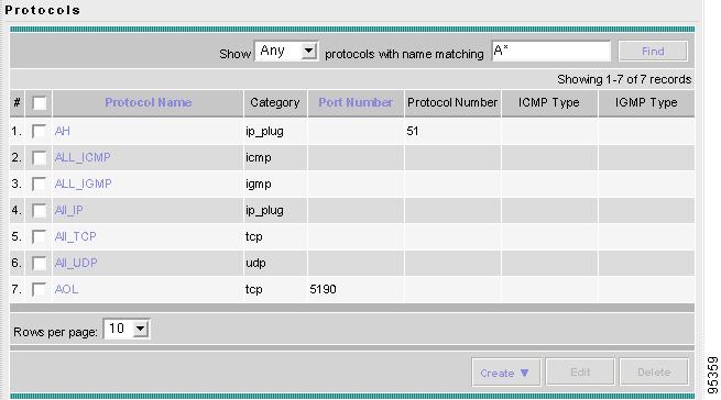
Step 1
Figure 6-30 Protocols
Proceed to one of the following:
•
•
•
•
•
•
•
Create TCP
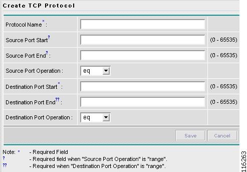
To create a TCP protocol, navigate Service Design > Protocols, choose Protocols, and follow these steps:
Step 1
Step 2
Figure 6-31 Create TCP Protocol
Enter the following fields:
•
•
•
•
•
•
•
Click Save.
Step 3
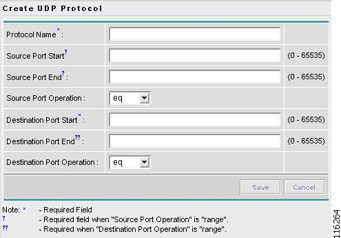
Create UDP
To create a UDP protocol, navigate Service Design > Protocols, choose Protocols, and follow these steps:
Step 1
Step 2
Figure 6-32 Create UDP Protocol
Enter the following fields:
•
•
•
•
•
•
•
Click Save.
Step 3
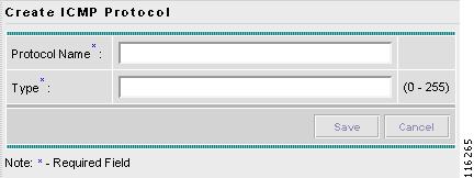
Create ICMP
To create an ICMP protocol, navigate Service Design > Protocols, choose Protocols, and follow these steps:
Step 1
Step 2
Figure 6-33 Create ICMP Protocol
Enter the following fields:
•
•
Step 3
Step 4
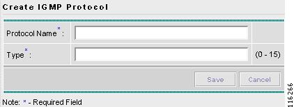
Create IGMP
To create an IGMP protocol, navigate Service Design > Protocols, choose Protocols, and follow these steps:
Step 1
Step 2
Figure 6-34 Create IGMP Protocol
Enter the following fields:
•
•
Step 3
Step 4
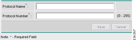
Create IP
To create an IP protocol, navigate Service Design > Protocols, choose Protocols, and follow these steps:
Step 1
Step 2
Figure 6-35 Create IP Protocol
Enter the following fields:
•
•
Step 3
Step 4
Edit
From Figure 6-30, do the following to edit a protocol:
Step 1
Click the Edit button and a window as shown in the create section for this protocol type appears, except that this is an Edit window and the Name cannot be changed. Complete the remaining fields as explained in the Create sections. And then click Save.
Step 2
Delete
From Figure 6-30, do the following to delete protocols:
Step 1
Click the Delete button and a Confirm Delete window gives you the opportunity to continue, by clicking Delete or cancel the delete process by clicking Cancel.
Step 2
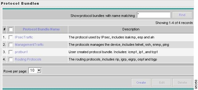
Protocol Bundles
Protocol Bundles allows you to group Protocols and to use them as a single entity.
All the possible choices for Protocols Bundles can be handled as follows:
Step 1
Figure 6-36 Protocols Bundles
Proceed to one of the following:
•
•
•
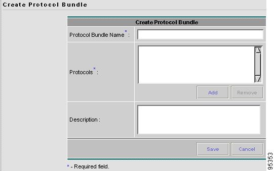
Create Protocol Bundles
Navigate Service Design > Protocols, choose Protocol Bundles, and follow these steps:
Step 1
Step 2
Figure 6-37 Create Protocol Bundles
Enter the following fields:
•
•
Description (optional) This information is for clarity of description of the protocol bundle.
Step 3
Step 4
Edit Protocol Bundles
From Figure 6-36, do the following to edit a protocol bundle:
Step 1
Click the Edit button and a window as shown in Figure 6-37 appears, except that this is an Edit Protocol Bundle window and the Name cannot be changed. Complete the remaining fields as explained in the "Create Protocol Bundles" section. And then click Save.
Step 2
Delete Protocol Bundles
From Figure 6-36, do the following to delete protocol bundles:
Step 1
Click the Delete button and a Confirm Delete window gives you the opportunity to continue, by clicking Delete or cancel the delete process by clicking Cancel.
Step 2
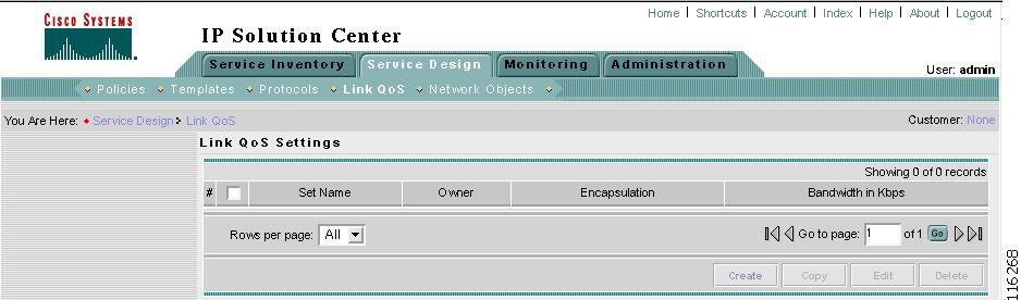
Link QoS
The Link QoS deals with link-level QoS settings such as Aggregate Shapers (FRTS; ATM Shapers, parent-level cb-shaper), Link Efficiency Mechanisms (FRF.12, LFIoMLPPP, and cRTP), and Interface-based CAR, those that depend on Layer2 encapsulation and link bandwidth.
You can create a link QoS setting for a network independent of a VPN service. To create a Link QoS setting for an MPLS service, see Cisco IP Solution Center Quality of Service User Guide, 4.0.
When you navigate Service Design > Link QoS, a window appears, as shown in Figure 6-38, "Link QoS Settings."
Figure 6-38 Link QoS Settings
The current Link QoS settings are available for QoS service requests, including the following information about each Link QoS setting:
•
•
•
•
The explanation of the buttons and subsequent drop-down menus is given as follows:
•
•
•
•
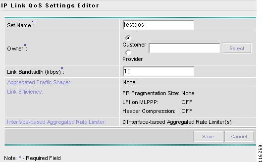
Create
When you navigate Service Design > Link QoS, click the Create button at the bottom of the window, as shown in Figure 6-38. To create IP Link QoS settings, proceed as follows:
Step 1
Figure 6-39 IP Link Settings Editor
Step 2
•
•
•
•
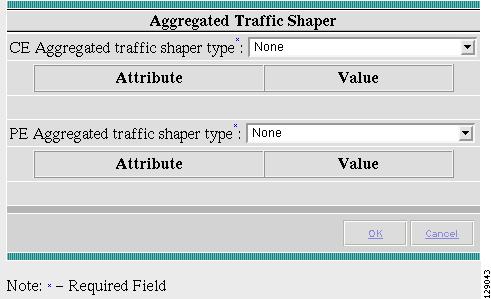
Figure 6-40 Aggregated Traffic Shaper
–
FR Traffic Shaper Frame Relay Traffic Shaper. Class-based Parent-level Shaper that operates only in distributed mode on VIP-based routers, such as the Cisco 7500 series platforms.
FR Traffic Shaper (non-MQC) Frame Relay Traffic Shaper. This shaper operates on 72xx and low-end routers.
Parent-level Class-based Shaper Used in the context of nested policy. A nested policy consists of a bottom-level policy that identifies one or more classes of traffic, and a top-level policy that shapes the output of the traffic classes into a single shape rate. You can apply a nested policy to an interface or subinterface.
ATM Traffic Shaper (VBR-rt) Variable bit rate-real time Intended for real-time applications, such as compressed voice over IP and video conferencing, that require tightly constrained delays (cell transfer delay or cell delay variation).
ATM Traffic Shaper (VBR-nrt) Variable bit rate-non real time Follows a leaky bucket or token bucket algorithm.
ATM Traffic Shaper (CBR) Constant bit rate Designed for ATM virtual circuits (VCs) that need a static amount of bandwidth that is continuously available for the duration of the active connection.
ATM Traffic Shaper (ABR) Configures a router to transmit at a rate that varies with the amount of bandwidth available in the network or along the end-to-end transmission path.
None
–
•
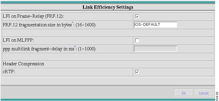
Figure 6-41 Link Efficiency Settings
–
LFI on Frame Relay (FRF.12) (default) Supports the transport of real-time voice and data traffic on Frame Relay virtual circuits (VCs) without causing excessive delay to the real-time traffic. If you choose this, you can override the following field with a number (16 - 1600), which specifies the fragmentation size in bytes.
or
LFI on MLPP Multilink PPP (MLPPP) provides a method of splitting, recombining, and sequencing datagrams across multiple logical data links. MLPPP allows packets to be fragmented and the fragments to be sent at the same time over multiple point-to-point links to the same remote address.
–
–
•
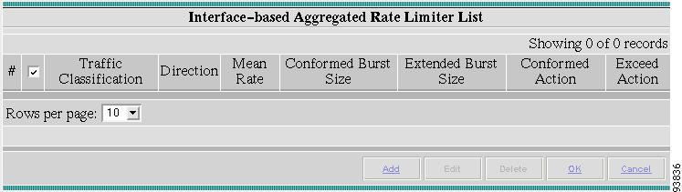
Figure 6-42 Interface-based Aggregated Rate Limiter List
–
Traffic Classification (required) Specifies the method for classifying traffic. Click Edit to access the Traffic Classification Editor and choose from these selections.
Direction (required) Click the drop-down menu and choose OUTPUT (default) or INPUT. This specifies the direction of traffic to apply rate limiting parameters to.
Mean Rate in bps: (8000 - 2000000000) (required).
Conformed burst size in bytes: (1000 - 512000000) (required).
Extended burst size in bytes: (2000 - 1024000000) (required).
Conform—Action (required) Click the drop-down menu and choose: Transmit, which sends the packet; Drop, which drops the packet; Set-dscp-transmit, which sets the DSCP value and transmits the packet (must additionally specify a DSCP value in the drop-down menu); Set-prec-transmit, which sets the IP Precedence (0 to 7) values and sends the packet (must additionally specify an IP Precedence value in the drop-down menu); Set-mpls-exp-transmit, which sets the mpls experimental (0 to 7) values and sends the packet (must additionally specify an mpls experimental value in the drop-down menu); Set-dscp-continue, which sets the DSCP value and transmits the packet (must additionally specify a DSCP value in the drop-down menu); Set-prec-continue, which sets the IP Precedence (0 to 7) values and sends the packet (must additionally specify an IP Precedence value in the drop-down menu); or Set-mpls-exp-continue, which sets the mpls experimental (0 to 7) values and sends the packet (must additionally specify an mpls experimental value in the drop-down menu).
Exceed—Action (required) Click the drop-down menu and use the same choices as in Conform—Action to specify how to handle packets that exceed the configured rate limit.
–
–
Note
–
–
Step 3
Step 4
Copy
The Copy button at the bottom of Figure 6-38, allows you to create a copy of a Link QoS and then make changes and save it with a new name.
Edit
The Edit button, at the bottom of Figure 6-38, allows you to edit a specific link QoS setting. Follow these steps:
Step 1
Step 2
Step 3
The Owner cannot be changed.
Step 4
Delete
The Delete button, at the bottom of Figure 6-38, allows you to delete one or more link QoS settings. Follow these steps:
Step 1
Step 2
Step 3
Note
Network Objects
- This feature is NOT SUPPORTED in this release. -
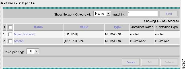
Network Objects allows you to create network objects. When you define a network object, you can use this object in a QoS policy or Firewall policy- Firewall policy is NOT SUPPORTED in this release. - rather than using the actual address itself. This simplifies Firewall policy- Firewall policy NOT SUPPORTED in this release. - or QoS policy creation.
From Figure 6-1, navigate Service Design > Network Objects and follow these steps:
Step 1
Figure 6-43 Network Objects
Step 2
•
•
•
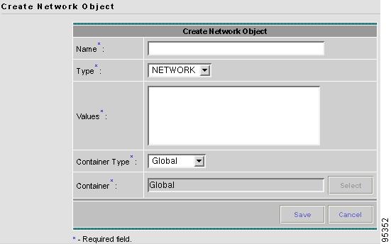
Create Network Objects
From Figure 6-43, do the following to create a network object:
Step 1
Step 2
Figure 6-44 Create Network Object
Enter the following information:
•
•
•
•
•
Step 3
Step 4
Step 5
Step 6
Edit Network Objects
From Figure 6-43, do the following to edit a network object:
Step 1
Click the Edit button and a window as shown in Figure 6-44 appears, except that this is an Edit Network Object window and the Name cannot be changed. Complete the remaining fields as explained in the "Create Network Objects" section. And then click Save.
Step 2
Delete Network Objects
From Figure 6-43, do the following to delete network objects:
Step 1
Click the Delete button and a Confirm Delete window gives you the opportunity to continue, by clicking Delete or cancel the delete process by clicking Cancel.
Step 2