-
Cisco Active Network Abstraction Administrator Guide, 3.6
-
Introducing Cisco ANA
-
Getting Started With Cisco ANA Manage
-
Deploying Cisco ANA
-
Using Cisco ANA Manage Tables
-
Managing Cisco ANA Units
-
Managing AVMs and VNEs
-
Managing Global Settings
-
Managing Links
-
Managing Workflows
-
Managing Security
-
Database Backup and Restore
-
Utility Scripts
-
Golden Source Registry
-
Ports Used By Cisco ANA
-
Drools Rules Engine
-
VNE Persistency Mechanism
-
Index
-
 Feedback
Table Of Contents
Admin and Oper Mode AVM Status
Viewing and Editing an AVM's Properties
Admin and Oper Mode VNE Status
Public Key and Private Key File Formats
Viewing and Editing a VNE's Properties
Moving Multiple and Single VNEs
Managing AVMs and VNEs
This chapter describes defining and managing autonomous virtual machines (AVM) and virtual network elements (VNE).
•
Creating AVMs—Describes how to define an AVM for a Cisco ANA unit server.
•
•
•
•
•
•
•
•
•
•
•
•
Creating AVMs
Cisco ANA Manage enables the user to define AVMs for Cisco ANA unit servers. Every AVM in the Cisco ANA fabric is by default managed by the watchdog protocol. Cisco ANA Manage enables the administrator to define AVMs for units, and enable or disable the watchdog protocol on the AVM.
In order to define an AVM:
•
•
•
Note
•
Note
To create an AVM:
Step 1
Step 2
Step 3
The following fields are displayed in the New AVM dialog box:
•
Note
•
Note
•
•
The following checkboxes are displayed in the New AVM dialog box:
•
•
Note
If this option is selected or unchecked when the AVM is up then you will need to restart the AVM in order for this change to take affect.Step 4
Step 5
Creating the new AVM results in Cisco ANA providing the registry information of the new AVM in the specified unit. The AVM can now host VNEs. For more information, see Defining VNEs.
AVM Status
The status of AVMs and VNEs is affected by Admin and Oper modes. Admin mode is the administrative instructions that are sent to the AVM. Oper mode is the actual status of the AVM, for example, Up. See Admin and Oper Mode AVM Status.
When moving an AVM (file), its status, for example, Up or Down, has a bearing on whether the file is reloaded (Up) or not (Down). For more information about moving AVMs, see Moving AVMs. For more information about starting and stopping AVMs, see Starting and Stopping AVMs.
An AVM can have only one of the following statuses at a time:
•
•
•
•
Admin and Oper Mode AVM Status
The AVM status table describes the status of an AVM depending on the Admin and Oper modes, as displayed in the Status column of the AVMs table. The Admin mode is the administrative instructions that are sent to the VNE. The Oper mode is the actual status of the VNE, for example, Up.
Table 6-1 AVM Status
Up
Up
Up
Shutting Down
Down
Up
Down
Down
Down
Starting Up
Up
Down
Viewing and Editing an AVM's Properties
Cisco ANA Manage enables the user to view and edit the properties of an AVM, for example, the key, and the allocated memory.
To view and edit an AVM's properties:
Step 1
Step 2
Step 3
The AVM Properties dialog box is displayed with the details of the selected AVM, including the IP address or key of the unit.
The following field is displayed in the AVM Properties dialog box:
•
Step 4
Note
Step 5
Deleting an AVM
The user can remove an AVM. If the AVM is running it will be stopped before removal. This procedure deletes the registry information of the AVM in the specified unit. If there are VNEs running in the AVM, then an error message will be displayed, and the user will be unable to delete the AVM.
Warning
For more information, see Deleting a VNE.
Note
To delete an AVM:
Step 1
Step 2
Step 3
Step 4
Step 5
Note
Starting and Stopping AVMs
Cisco ANA Manage enables the user to start or stop an AVM.
Note
To start or stop an AVM:
Step 1
Step 2
Step 3
The AVM is started or stopped, and the appropriate status is displayed in the workspace as follows:
•
•
•
•
Note
Moving AVMs
Cisco ANA Manage enables the administrator to move an entire AVM between units.
Note
Cisco ANA Manage automatically checks the status of the AVM and VNE before it is moved. This information is maintained in the memory.
If the AVM is Up it is stopped, and then it is moved to the target unit. After the move is completed, the AVM is reloaded according to its status prior to the move, namely, the status of the AVM as it was before the move is maintained. For example, if it was Up before the move it will remain Up, if it was Down it will remain Down.
To move an AVM:
Step 1
Step 2
Step 3
The Move To dialog box displays a tree-and-branch representation of the selected Cisco ANA server and its units, excluding the unit in which the AVM is currently located. The highest level of the tree displays the Cisco ANA server. The branches can be expanded and collapsed in order to display and hide information.
Step 4
Step 5
For information about moving VNEs, see Moving Multiple and Single VNEs.
Finding an AVM or VNE
A single search in Cisco ANA Manage can locate AVMs and VNEs among all Cisco ANA servers according to specifically defined search criteria.
To find an AVM or VNE:
Step 1
Step 2
The Find field enables the user to enter specific search criteria in order to find the required AVM or VNE. For example, the user can search for an AVM using the ID number, or search for a VNE using an IP address.
The Types list enables the user to specify whether the user is searching for an AVM or VNE by selecting an option from the list. When an option is selected from the list, then the Property area is enabled, displaying the properties for the selected option. For example, if AVM is selected from the Types list, then the AVM's properties are displayed in the Property area, and the user can select a specific property for the search.
The Up and Down radio buttons enable the user to search up and down (you can also use the F3 key).
The following buttons are displayed in the Find dialog box:
•
•
Step 3
When searching for an AVM the following search criteria are displayed:
•
•
•
•
When searching for a VNE the following search criteria are displayed:
•
•
•
•
•
•
Step 4
Step 5
Step 6
Step 7
Note
Overview Of VNEs
A VNE is designated by its leading IP address and corresponds to a single network element (NE). Typically an NE has only one IP address that is used for management. For such devices, the leading IP address is the single IP address configured for this device.
In cases where an NE has multiple IP addresses, the user must choose one of these IP addresses to be used as a leading IP address. The leading IP address serves as an identifier of the VNE that corresponds to the NE and is displayed wherever the IP address of the NE is required.
Note
Cisco ANA Manage enables the user to create VNEs (replicas of devices), for example, by entering the IP address, SNMP and polling rate information and so on. This is called Element Management.
After Cisco ANA Manage installs and runs the process, samples the device and collects the data, a VNE (managed element) is created. The VNE includes tables and physical inventory, and this managed element can be accessed using Cisco ANA NetworkVision.
VNE Status
The status of VNEs is affected by the Admin and Oper modes. Admin mode is the administrative instructions that are sent to the VNE. Oper mode is the actual status of the VNE, for example, Up. For more information about Admin and Oper modes, see Admin and Oper Mode VNE Status.
When moving a VNE, its status, for example, Up or Down, has a bearing on whether the VNE is reloaded (Up) or not (Down). For more information about moving VNEs, see Moving Multiple and Single VNEs. For more information about starting and stopping VNEs,
see Changing the VNE's State.A VNE can have only one of the following statuses at a time:
•
•
•
•
•
In addition to the statuses described, the VNE can be placed in maintenance mode, for example, a VNE's status can be Up and in maintenance mode. NEs often undergo maintenance operations and planned outages. The Cisco ANA platform supports such maintenance operations without affecting the overall functionality of the active network.
While in maintenance mode (temporary state) a VNE:
•
•
•
•
•
For more information about maintenance mode, see Changing the VNE's State.
Admin and Oper Mode VNE Status
The VNE status table describes the status of a VNE depending on the Admin and Oper modes, as displayed in the Status column of the VNE table. The Admin mode is the administrative instructions that are sent to the VNE. The Oper mode is the actual status of the VNE, for example, Up.
Table 6-2 VNE Status
Up
Up
Up
Shutting Down
Down
Up
Down
Down
Down
Starting Up
Up
Down
Unreachable
Up
Unreachable
For example, if the user starts the VNE, the Admin status is Up but the Oper status is Down and has not started yet (because the server is busy), the status is Starting Up. If the VNE is Up and running and the user stops the VNE, the Admin status is Down but the process is not terminated immediately, the status is Shutting Down.
Defining VNEs
When the user adds and defines a new VNE, it corresponds to an NE and should only be added to the system once. As the VNE loads, Cisco ANA starts investigating the NE and automatically builds a live model of it, including its physical and logical inventory, its configuration, and its status.
When adding a new VNE, Cisco ANA creates the registry information of the new VNE in the unit. The newly created VNE has an administrative status of Down, and uses the default community strings and polling rates. The VNE inherits these properties from the configuration record that corresponds to the device type.
A VNE must be loaded into the bootstrap of the unit before it starts monitoring its underlying NE. This changes the administrative status of the VNE to Up, and ensures that the VNE is loaded on subsequent restarts of the unit. Loading the VNE also starts the VNE immediately. For more information about the status of VNEs, see Admin and Oper Mode VNE Status.
Before adding a new VNE using Cisco ANA Manage, the user must first determine which unit and AVM the new VNE should be added to.
The user can define and manage SNMP, Telnet/SHH, ICMP, and polling information for the appropriate VNEs in the New VNE dialog box.
Note
The user can create VNEs that perform reachability testing only through ICMP. This can be done by creating the VNE, selecting the type ICMP, and then defining the details in the ICMP tab. See ICMP Tab.
For information on defining VNE properties in the respective VNE tabs, refer to the following:
For details on viewing and editing VNE properties,
see Viewing and Editing a VNE's Properties.To define the properties of a new VNE:
Step 1
Step 2
Step 3
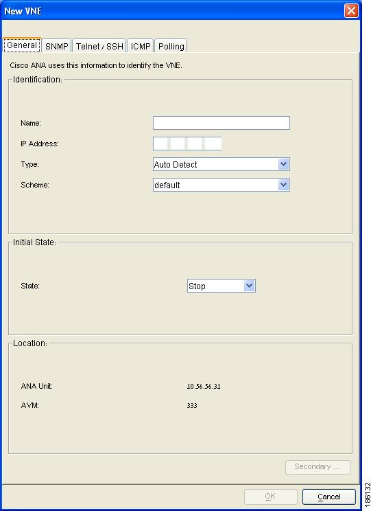
Figure 6-1 New VNE Dialog Box
The New VNE dialog box contains the following tabs:
•
•
•
•
•
Note
General Tab
The General tab enables the user to manage VNE information in the connected Cisco ANA.
The following VNE identification fields are displayed in the Identification area:
•
Note
•
•
–
Note
See SNMP Tab.–
–
–
Note
•
Note
The following VNE state fields are displayed in the initial state area:
•
–
–
–
VNE Status.The following fields are displayed in the Location area of the General tab:
•
•
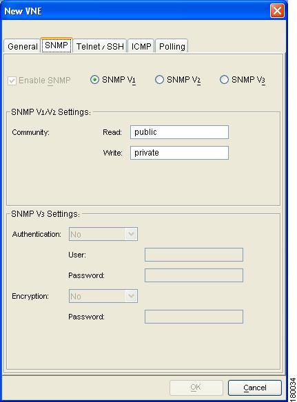
SNMP Tab
The SNMP tab enables the user to support polling and accessing devices using SNMPv1, SNMPv2 and SNMPv3. Selecting the SNMP tab displays the following dialog box:
Figure 6-2 SNMP Tab
The following checkbox and radio buttons are displayed in the SNMP tab of the New VNE dialog box:
•
Note
•
•
•
Note
The following fields are displayed in the SNMP V1/V2 Settings area:
•
•
Note
The following fields are displayed in the SNMP V3 settings area:
•
–
–
–
If MD5 or SHA is selected, enter the required information in the following fields:
–
–
•
–
–
–
–
–
If one of the security options is selected, enter the required information in the following field:
–
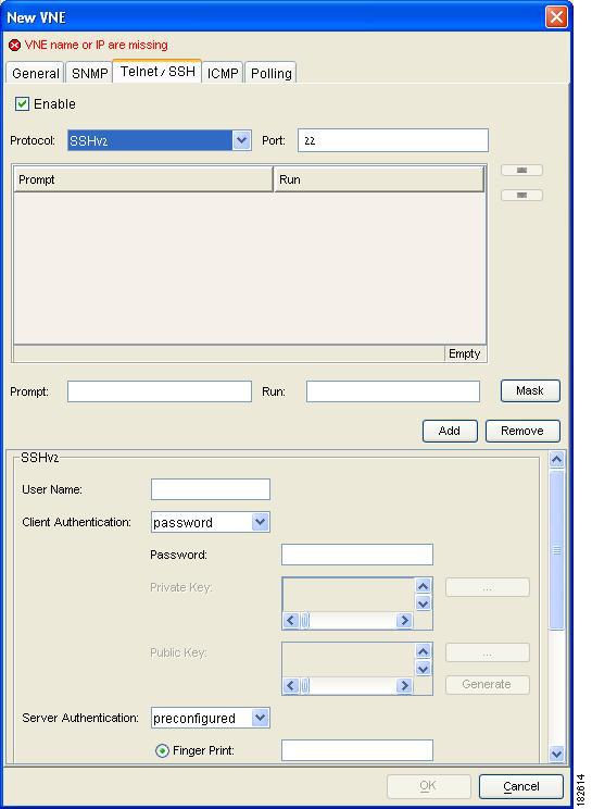
Telnet/SSH Tab
The Telnet/SSH tab enables the user to define the Telnet command sequence and support SSH for device access (reachability) and investigation. See SSHv2 Protocol for more information about the SSH protocol. Selecting the Telnet/SSH tab displays the following tabbed dialog box:
Figure 6-3 Telnet/SSH Tab
Note
There is no more enable/disable of fields.
The following checkbox is displayed in the Telnet/SSH tab of the New VNE dialog box:
•
Note
The following fields are displayed in the Telnet/SSH tab of the New VNE dialog box:
•
–
–
–
•
Device credentials in the GUI can be masked with asterisks. Click Mask. A Password Controller window opens, enter the password and confirm it. An error message is shown if one of the fields is missing, or the password and confirm strings are not identical. Click OK. The Password Controller window closes, and the password is inserted in the Run text field as asterisks. The Run text field will stay masked until you add the prompt to the sequence.
If you do not click Mask, the password is entered as regular text.
The Run column in theTelnet sequence table displays the data in regular text or as asterisks depending on the chosen option.
•
•
The following buttons are displayed in the Telnet/SSH tab of the New VNE dialog box:
•
•
Use the Up and Down arrows to change the order of the commands in the list.
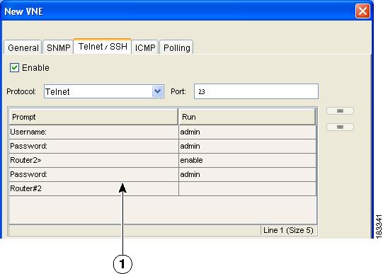
Note
Figure 6-4 Telnet Sequence Ending With Prompt Field
SSHv1 Protocol
If the SSHv1 protocol is selected, enter the required information and properties in the following fields:
•
•
•
•
SSH Login Sequence
After an SSH session is established between the VNE and the device, the VNE will start the login sequence. This sequence is usually shorter than the corresponding Telnet login sequence, as the user name and/or the password may already be sent as part of establishing the SSH session.
It is recommended to first use any SSH client application, for example unix-ssh or openSSH, to see what is the device valid SSH login sequence and then fill the sequence into the VNE configuration.
SSHv2 Protocol
Secure Shell (SSH) is a protocol that provides a secure session using standard cryptographic mechanisms.
SSH Login Sequence
For information on the SSH login sequence see SSH Login Sequence.
Client-Authentication
You need to enter your username and either a password or a private key according to the configured authentication option on the device.
Public key client authentication uses a key pair system in which the client application is configured with the secret private key and the device is configured with the public non-secret key of this pair.
You must enter a private key. You can copy and paste it, or upload it from a file, click Browse for file ....
Entering the matching public key is optional. If it is completed, the application will verify that the public and private key are a part of the pair. You may also click Generate to generate the matching public key using the private key information.
Supported Algorithms
At least one algorithm must be selected in each subject (key-exchange, MAC, cipher, host-key). If more than one is selected, the application will try to use all of the algorithms until one is accepted by the server. There is no priority in the way the algorithms are tried.
Note
Cisco ANA supports the algorithms which are commonly used in network devices as follows:
•
–
–
–
–
•
–
–
–
–
•
–
–
•
–
–
Server Authentication
Most of the devices which support SSH have a means of identifying themselves to the clients, so the clients are sure that the server is not an imposter.
The server will have a permanent server public key and it will pass it in each session negotiation. The client will compare this public key to the known public key of the server. If they match, the client can be sure of the authenticity of the server.
There are several methods that the VNE supports to do this authentication:
•
•
For all the later connections, authentication will be done against the data saved in the first connection. This method assumes the first connection was legitimate and compares all later connections to it . Note that a security risk still exists if the first connection was compromised.
After the first connection, this option will automatically be changed into "pre-configured" and the public key data of the session will be inserted as the pre-configured data.
•
If the server fails to authenticate itself using the pre-configured data, the connection will fail. This is the default behaviour and is the recommended security option.
The pre-configured data can be of one of two types:
–
–
Public Key and Private Key File Formats
There are several file formats for public and private RSA and DSA keys, the same key can be written differently according to which format is used.
This application officially supports the openSSH format. For more details, see http://www.openssh.com/manual.html.
Make sure that the keys you provide as input parameters are in this format. If they are not, you will need to convert them to the open SSH format before applying them.
Use Case Example
When working with Cisco IOS, the public key is retrieved using show crypto key mypubkey .... This format is not compatible with the OpenSSH format, and is not supported. There are several ways to convert the format.
The easiest solution is to use public key scan by the (free) openSSH application to retrieve the public key in the supported format. For more details, see http://www.openssh.com/manual.html.
Another option is to convert the files to the required format either manually or using a script.
Examples of Valid File Formats
RSA- private key-----BEGIN RSA PRIVATE KEY-----MIICWwIBAAKBgQDvdpW8ItfbSp/hTbWZJqCPmjRyh9S+EpTJ0Aq3fnGpFPTR+........TiOfhiuX5+M1cTaE/if8sScj6jE9A0MpShBrnDU/0A==-----END RSA PRIVATE KEY-----DSA private key-----BEGIN DSA PRIVATE KEY-----MIIBuwIBAAKBgQDNGO+l2XW+W+YtVnWSYbKXr6qkrH9nOl+.........7wO4+FR9afoRjDusrQrL-----END DSA PRIVATE KEY-----DSA public keyssh-dss AAAAB3.........HfuNYu+ DdGY7njEYrN++iWs= aslehr@aslehr-wxp01RSA - public keyssh-rsa AAAAB3...lot more...qc8Hc= aslehr@aslehr-wxp01ICMP Tab
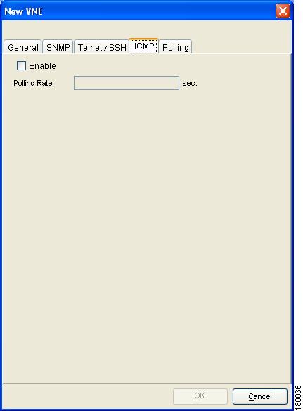
The ICMP tab enables repetitive sending of packets to a device to verify that the device is reachable. The user can define the polling rate in seconds for the VNE. Select the ICMP tab to display the ICMP tab in the New VNE dialog box.
Figure 6-5 ICMP Tab
The following checkbox is displayed in the ICMP tab of the New VNE dialog box:
•
Note
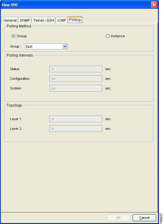
Polling Tab
When customizing polling rates, special consideration should be given to the following:
Warning
The Polling tab enables the administrator to:
•
•
–
–
–
–
In addition, a polling interval can be configured for a class of devices, for example, for all Cisco routers.
Select the Polling tab to display the following dialog box:
Figure 6-6 Polling Tab
The following radio buttons are displayed in the Polling Method area:
•
For more information about creating customized polling groups, see Chapter 7, "Managing Global Settings".
Note
•
Note
Note
The following polling interval fields are displayed in the Polling Intervals area:
•
•
•
The following fields are displayed in the Topology area:
•
•
Defining a Generic SNMP VNE
The generic SNMP VNE is a VNE that is not related to any vendor, and can represent any vendor (with certain limitations), and provide lightweight management support for network devices.
The generic VNE provides basic management capabilities for a device with the following technologies:
•
•
•
Note
The generic SNMP VNE supports the following inventory items:
•
•
•
•
•
There are two different scenarios that can occur when loading the generic SNMP VNE:
1.
Cisco ANA Manage enables the user to load a VNE as a generic SNMP VNE. The user does this by selecting the Generic SNMP option in the Type field of the New VNE dialog box. For more information about how to define a generic SNMP VNE, see Defining VNEs.
2.
If the device is not found in the "deviceTypes" list, it is currently unsupported and the user can load the VNE as:
–
–
Every VNE in "agentdefaults/da" has the entry "load generic agent for unsupported device type", where the user can set the value as "true" or "false" (the default is "false"). If the value is "true", it sets "1.3.999.3" as the property. It looks for this property in "agentdefaults/da/deviceTypes" and finds "sheer/genericda". It then skips the investigation of the device's software versions and builds the VNE (generic SNMP) from the default version.
Polling System Configuration
The sysoid command and the software version command are used to poll the system configuration. The following parameters are available:
•
•
Note
Viewing and Editing a VNE's Properties
Cisco ANA Manage enables the user to view and edit the properties of a VNE in a unit, for example, the status and Telnet settings. See Defining VNEs.
To edit a VNE's properties:
Step 1
Step 2
Step 3
For more details about the fields displayed in the VNE Properties dialog box, see
Defining VNEs. In addition to the fields displayed when adding a new VNE, the following fields and buttons are displayed:•
•
•
•
•
•
Step 4
Step 5
Step 6
Deleting a VNE
Cisco ANA Manage enables the user to delete a VNE from a unit and AVM. This process stops the VNE if it is running, and deletes all VNE references from the system and Golden Source. This includes the registry information of the VNE in the specified unit. A VNE that has been removed no longer appears in any future system reports.
Since all VNE information is deleted, adding the VNE again requires the user to enter all the VNE information.
Note
To delete a VNE:
Step 1
Step 2
Step 3
Step 4
Step 5
Changing the VNE's State
Cisco ANA Manage enables the user to start or stop a VNE, or move a VNE to maintenance mode. Starting the VNE adds the VNE to the server bootstrap. Stopping the VNE removes the VNE from the server bootstrap.
During normal operation, NEs often undergo maintenance operations and planned outages such as software upgrades, hardware modifications, cold reboots and so on. The Cisco ANA platform supports such maintenance operations without affecting the overall functionality of the active network. Neighboring VNEs do not generate alarms that are related to links to or from the maintained VNE.
While in maintenance state (temporary state) a VNE:
•
•
•
•
•
The VNE blocks all provisioning flows that run through the VNE. A device in maintenance state can be disconnected and restarted, and this does not result in link-down alarms. Upon restart, the VNE receives only persistent information and returns to its latest known configuration. The topology links are renewed automatically.
To change the VNE's state:
Step 1
Step 2
Step 3
Step 4
•
•
•
Step 5
•
In cases where the AVM hosting the VNE is still in a Down status, the VNE status will remain as Starting Up until the AVM is brought up.
•
•
Moving Multiple and Single VNEs
Cisco ANA Manage enables the administrator to move single and multiple VNEs between AVMs. The VNEs that are moved are unloaded. The status of the VNEs is maintained after they are reloaded.
To move a single VNE or multiple VNEs:
Step 1
Step 2
Step 3
Step 4
The Move To dialog box displays a tree-and-branch representation of the selected Cisco ANA server, its units and AVMs, excluding the AVM in which the VNE is currently located. The highest level of the tree displays the Cisco ANA server. The branches can be expanded and collapsed in order to display and hide information.
Step 5
Step 6
Note
Note