-
Cisco MWR 2941 Mobile Wireless Edge Router Software Configuration Guide, Release 15.0(1)MR
-
About This Guide
-
Cisco MWR 2941 Router Overview
-
Cisco IOS Software Basics
-
First-Time Configuration
-
Configuring Gigabit Ethernet Interfaces
-
Configuring Layer 2 Interfaces
-
Configuring HWIC-9ESW Interfaces
-
Configuring VLANs
-
Configuring IEEE 802.1Q Tunneling, VLAN Mapping, 802.1ad, and Layer 2 Protocol Tunneling
-
Configuring STP
-
Configuring MSTP
-
Configuring Optional Spanning-Tree Features
-
Managing the MAC Address Table
-
Configuring Cisco Express Forwarding
-
Configuring Resilient Ethernet Protocol
-
Configuring Ethernet Link Operations, Administration, and Maintenance
-
Configuring Clocking and Timing
-
Configuring Synchronous Ethernet ESMC and SSM
-
Configuring MLPPP Backhaul
-
Configuring Multiprotocol Label Switching
-
Configuring Routing Protocols
-
Configuring Bidirectional Forwarding Detection
-
Configuring Pseudowire
-
Configuring Layer 3 Virtual Private Networks
-
Configuring Quality of Service
-
Configuring Link Noise Monitor
-
Configuring Cisco Discovery Protocol
-
Monitoring and Managing the Cisco MWR 2941 Router
-
Index
-
 Feedback
Table Of Contents
Default Ethernet VLAN Configuration
Creating or Modifying an Ethernet VLAN
Assigning Static-Access Ports to a VLAN
Creating an Extended-Range VLAN with an Internal VLAN ID
Configuring VLAN Trunking Protocol
IEEE 802.1Q Configuration Considerations
Default Layer 2 Ethernet Interface VLAN Configuration
Configuring an Ethernet Interface as a Trunk Port
Interaction with Other Features
Defining the Allowed VLANs on a Trunk
Configuring the Native VLAN for Untagged Traffic
Configuring Trunk Ports for Load Sharing
Load Sharing Using STP Port Priorities
Load Sharing Using STP Path Cost
Configuring VLANs
This chapter describes how to configure normal-range VLANs (VLAN IDs 1 to 1005) and extended-range VLANs (VLAN IDs 1006 to 4094) on the Cisco MWR 2941 router. It includes information about VLAN membership modes, VLAN configuration modes, and VLAN trunks.
Note
For complete syntax and usage information for the commands used in this chapter, see the command reference for this release.
Understanding VLANs
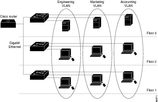
A VLAN is a switched network that is logically segmented by function, project team, or application, without regard to the physical locations of the users. VLANs have the same attributes as physical LANs, but you can group end stations even if they are not physically located on the same LAN segment. Any switch port can belong to a VLAN, and unicast, broadcast, and multicast packets are forwarded and flooded only to end stations in the VLAN. Each VLAN is considered a logical network, and packets destined for stations that do not belong to the VLAN must be forwarded through a router, as shown in Figure 7-1. Because a VLAN is considered a separate logical network, it contains its own bridge MIB information and can support its own implementation of spanning tree. See Chapter 9 "Configuring STP."
Figure 7-1 shows an example of VLANs segmented into logically defined networks.
Figure 7-1 VLANs as Logically Defined Networks
VLANs are often associated with IP subnetworks. For example, all the end stations in a particular IP subnet belong to the same VLAN. Interface VLAN membership on the switch is assigned manually on an interface-by-interface basis. When you assign switch interfaces to VLANs by using this method, it is known as interface-based, or static, VLAN membership.
Traffic between VLANs must be routed. Switches that are running the metro IP access image can route traffic between VLANs by using switch virtual interfaces (SVIs). To route traffic between VLANs, an SVI must be explicitly configured and assigned an IP address. For more information, see the Interface and Hardware Component Configuration Guide, Cisco IOS Release 15.0S..
This section includes these topics:
Supported VLANs
VLANs are identified with a number from 1 to 4094. VLAN IDs 1002 through 1005 are reserved for Token Ring and FDDI VLANs. VLAN IDs greater than 1005 are extended-range VLANs and are not stored in the VLAN database.
Although the router supports a total of 1005 (normal-range and extended-range) VLANs, the number of routed ports, SVIs, and other configured features affects the use of the switch hardware.
The router supports Per VLAN Spanning Tree Plus (PVST+) with a maximum of 128 spanning-tree instances. One spanning-tree instance is allowed per VLAN.
Note
Note
See the "VLAN Configuration Guidelines" section for more information about the number of spanning-tree instances and the number of VLANs. The switch supports IEEE 802.1Q trunking for sending VLAN traffic over Ethernet ports.
Normal-Range VLANs
Normal-range VLANs are VLANs with VLAN IDs 1 to 1005. You can add, modify or remove configurations for VLANs 2 to 1001 in the VLAN database. (VLAN IDs 1 and 1002 to 1005 are automatically created and cannot be removed.)
Configurations for VLAN IDs 1 to 1005 are written to the file vlan.dat (VLAN database), and you can display them by entering the show vlan privileged EXEC command. The vlan.dat file is stored in flash memory.
Caution
You can set these parameters when you create a new normal-range VLAN or modify an existing VLAN in the VLAN database:
•
•
•
Note
•
•
•
•
•
•
•
•
Note
Extended-Range VLANs
You can create extended-range VLANs (in the range 1006 to 4094) to enable service providers to extend their infrastructure to a greater number of customers. The extended-range VLAN IDs are allowed for any switchport commands that allow VLAN IDs. Extended-range VLAN configurations are not stored in the VLAN database, but they are stored in the switch running configuration file, and you can save the configuration in the startup configuration file by using the copy running-config startup-config privileged EXEC command.
Note
VLAN Port Membership Modes
You configure a port to belong to a VLAN by assigning a membership mode that specifies the kind of traffic that the port carries and the number of VLANs to which it can belong. Table 7-1 lists the membership modes and characteristics.
Table 7-1 Port Membership Modes
Static-access
A static-access port can belong to one VLAN and is manually assigned to that VLAN.
For more information, see the "Assigning Static-Access Ports to a VLAN" section.
Trunk (IEEE 802.1Q)
A trunk port is a member of all VLANs by default, including extended-range VLANs, but membership can be limited by configuring the allowed-VLAN list.
For information about configuring trunk ports, see the "Configuring an Ethernet Interface as a Trunk Port" section.
Tunnel
(dot1q-tunnel)Tunnel ports are used for IEEE 802.1Q tunneling to maintain customer VLAN integrity across a service-provider network. You configure a tunnel port on an edge switch in the service-provider network and connect it to an IEEE 802.1Q trunk port on a customer interface, creating an assymetric link. A tunnel port belongs to a single VLAN that is dedicated to tunneling.
For more information about tunnel ports, see Chapter 8 "Configuring IEEE 802.1Q Tunneling and Layer 2 Protocol Tunneling."
For more detailed definitions of access and trunk modes and their functions, see Table 7-4.
When a port belongs to a VLAN, the switch learns and manages the addresses associated with the port on a per-VLAN basis. For more information, see the Chapter 12 "Managing the MAC Address Table.".
Creating and Modifying VLANs
You use VLAN configuration mode, accessed by entering the vlan global configuration command to create VLANs and to modify some parameters. You use the interface configuration mode to define the port membership mode and to add and remove ports from VLANs. The results of these commands are written to the running-configuration file, and you can display the file by entering the show running-config privileged EXEC command.
These sections contain VLAN configuration information:
•
•
•
•
•
For more efficient management of the MAC address table space available on the switch, you can control which VLANs learn MAC addresses by disabling MAC address learning on specific VLANs. See the "Managing the MAC Address Table" section for more information.
Default Ethernet VLAN Configuration
The switch supports only Ethernet interfaces. Table 7-2 shows the default configuration for Ethernet VLANs.
Note
VLAN Configuration Guidelines
Follow these guidelines when creating and modifying VLANs in your network:
•
•
•
•
•
•
If the number of VLANs on the switch exceeds the number of supported spanning-tree instances, configure the IEEE 802.1s Multiple STP (MSTP) on your switch to map multiple VLANs to a single spanning-tree instance. For more information about MSTP, see Chapter 10 "Configuring MSTP."
Note
•
–
–
–
•
Creating or Modifying an Ethernet VLAN
To access VLAN configuration mode, enter the vlan global configuration command with a VLAN ID. Enter a new VLAN ID to create a VLAN, or enter an existing VLAN ID to modify that VLAN. You can use the default VLAN configuration (Table 7-2) or enter commands to configure the VLAN.
Note
For more information about commands available in VLAN configuration mode, see the vlan command description in the command reference for this release. When you have finished the configuration, you must exit VLAN configuration mode for the configuration to take effect. To display the VLAN configuration, enter the show vlan privileged EXEC command.
The configurations of VLAN IDs 1 to 1005 are always saved in the VLAN database (vlan.dat file) with a VLAN number and name and in the switch running configuration file. Extended-range VLANs are not saved in the VLAN database; they are saved in the switch running configuration file. You can save the VLAN configuration in the switch startup configuration file by using the copy running-config startup-config privileged EXEC command.
Note
Follow these steps to create or modify an Ethernet VLAN:
To delete a VLAN, use the no vlan vlan-id global configuration command. You cannot delete VLAN 1 or VLANs 1002 to 1005.
Caution
To return the VLAN name to the default settings, use the no name or no mtu VLAN configuration command.
This example shows how to create Ethernet VLAN 20, name it test20, and add it to the VLAN database:
Router# configure terminalRouter(config)# vlan 20Router(config-vlan)# name test20Router(config-vlan)# endThis example shows how to create a new extended-range VLAN with all default characteristics, enter config-vlan mode, and save the new VLAN in the switch startup configuration file:
Router(config)# vlan 2000Router(config-vlan)# endRouter# copy running-config startup configAssigning Static-Access Ports to a VLAN
You can assign a static-access port to a VLAN.
Note
Beginning in privileged EXEC mode, follow these steps to assign a port to a VLAN in the VLAN database:
To return an interface to its default configuration, use the default interface interface-id interface configuration command.
This example shows how to configure a port as an access port in VLAN 2:
Router# configure terminalEnter configuration commands, one per line. End with CNTL/Z.Router(config)# interface fastethernet0/1Router(config-if)# switchport mode accessRouter(config-if)# switchport access vlan 2Router(config-if)# endCreating an Extended-Range VLAN with an Internal VLAN ID
If you enter an extended-range VLAN ID that is already assigned to an internal VLAN, an error message appears, and the extended-range VLAN is rejected. To manually release an internal VLAN ID, you must temporarily shut down the routed port that is using the internal VLAN ID.
Beginning in privileged EXEC mode, follow these steps to release a VLAN ID that is assigned to an internal VLAN and to create an extended-range VLAN with that ID:
Configuring VLAN Trunking Protocol
This section describes how to configure the VLAN Trunking Protocol (VTP) on an EtherSwitch HWIC, and contains the following tasks:
Configuring a VTP Server
When a router is in VTP server mode, you can change the VLAN configuration and have it propagate throughout the network. Follow these steps to configure the router as a VTP server:
Configuring a VTP Client
When a router is in VTP client mode, you cannot change the VLAN configuration. A client switch receives VTP updates from a VTP server in the management domain and modifies its configuration accordingly. Follow these steps to configure the router as a VTP client.
Step 1
enable
Enter enable mode.
Step 2
configure terminal
Enter configuration mode.
Step 3
vtp mode client
Configure the switch as a VTP client.
Step 4
exit
Exit configuration mode.
Disabling VTP
You can disable VTP on the router by configuring it to VTP transparent mode, meaning that the router does not send VTP updates or act on VTP updates received from other switches. Follow these steps to disable VTP on the router:
Note
Displaying VLANs
Use the show vlan privileged EXEC command to display a list of all VLANs on the router, including extended-range VLANs. The display includes VLAN status, ports, and configuration information. Table 7-3 lists other privileged EXEC commands for monitoring VLANs.
For more details about the show command options and explanations of output fields, see the command reference for this release.
Configuring VLAN Trunks
•
•
•
Trunking Overview
A trunk is a point-to-point link between one or more Ethernet switch interfaces and another networking device such as a router or a switch. Ethernet trunks carry the traffic of multiple VLANs over a single link, and you can extend the VLANs across an entire network. The router supports the IEEE 802.1Q industry-standard trunking encapsulation.
Ethernet interfaces support different trunking modes (see Table 7-4). You can set an interface as trunking or nontrunking.
•
•
Table 7-4 Layer 2 Interface Modes
switchport mode access
Puts the interface (access port) into permanent nontrunking mode and negotiates to convert the link into a nontrunk link. The interface becomes a nontrunk interface regardless of whether or not the neighboring interface is a trunk interface. This is the default mode.
switchport mode trunk
Puts the interface into permanent trunking mode and negotiates to convert the neighboring link into a trunk link. The interface becomes a trunk interface even if the neighboring interface is not a trunk interface.
switchport mode dot1q-tunnel
Configures the interface as a tunnel (nontrunking) port to be connected in an asymmetric link with an IEEE 802.1Q trunk port. The IEEE 802.1Q tunneling is used to maintain customer VLAN integrity across a service provider network. See Chapter 8 "Configuring IEEE 802.1Q Tunneling and Layer 2 Protocol Tunneling," for more information on tunnel ports.
IEEE 802.1Q Configuration Considerations
The IEEE 802.1Q trunks impose these limitations on the trunking strategy for a network:
•
When you connect a Cisco switch to a non-Cisco device through an IEEE 802.1Q trunk, the Cisco switch combines the spanning-tree instance of the VLAN of the trunk with the spanning-tree instance of the non-Cisco IEEE 802.1Q switch. However, spanning-tree information for each VLAN is maintained by Cisco switches separated by a cloud of non-Cisco IEEE 802.1Q switches. The non-Cisco IEEE 802.1Q cloud separating the Cisco switches is treated as a single trunk link between the switches.
•
•
Default Layer 2 Ethernet Interface VLAN Configuration
Table 7-5 shows the default Layer 2 Ethernet interface VLAN configuration.
Configuring an Ethernet Interface as a Trunk Port
•
•
•
Interaction with Other Features
Trunking interacts with other features in these ways:
•
•
•
Configuring a Trunk Port
Beginning in privileged EXEC mode, follow these steps to configure a port as an IEEE 802.1Q trunk port:
To return an interface to its default configuration, use the default interface interface-id interface configuration command. To reset all trunking characteristics of a trunking interface to the defaults, use the no switchport trunk interface configuration command. To disable trunking, use the switchport mode access interface configuration command to configure the port as a static-access port.
This example shows how to configure a port as an IEEE 802.1Q trunk with VLAN 33 as the native VLAN:
Router# configure terminalEnter configuration commands, one per line. End with CNTL/Z.Router(config)# interface fastethernet0/2Router(config-if)# switchport mode trunkRouter(config-if)# switchport trunk native vlan 33Router(config-if)# endDefining the Allowed VLANs on a Trunk
By default, a trunk port sends traffic to and receives traffic from all VLANs. All VLAN IDs, 1 to 4094, are allowed on each trunk. However, you can remove VLANs from the allowed list, preventing traffic from those VLANs from passing over the trunk. To restrict the traffic a trunk carries, use the switchport trunk allowed vlan remove vlan-list interface configuration command to remove specific VLANs from the allowed list.
Note
To reduce the risk of spanning-tree loops or storms, you can disable VLAN 1 on any individual VLAN trunk port by removing VLAN 1 from the allowed list. When you remove VLAN 1 from a trunk port, the interface continues to send and receive management traffic, for example, Cisco Discovery Protocol.
If a trunk port with VLAN 1 disabled is converted to a nontrunk port, it is added to the access VLAN. If the access VLAN is set to 1, the port is added to VLAN 1, regardless of the switchport trunk allowed setting. The same is true for any VLAN that has been disabled on the port.
A trunk port can become a member of a VLAN if the VLAN is enabled and if the VLAN is in the allowed list for the port.
Beginning in privileged EXEC mode, follow these steps to modify the allowed list of an IEEE 802.1Q trunk:
To return to the default allowed VLAN list of all VLANs, use the no switchport trunk allowed vlan interface configuration command.
This example shows how to remove VLAN 2 from the allowed VLAN list on a port:
Router(config)# interface fastethernet0/1Router(config-if)# switchport trunk allowed vlan remove 2Router(config-if)# endConfiguring the Native VLAN for Untagged Traffic
A trunk port configured with IEEE 802.1Q tagging can receive both tagged and untagged traffic. By default, the router forwards untagged traffic in the native VLAN configured for the port. The native VLAN is VLAN 1 by default.
Note
For information about IEEE 802.1Q configuration issues, see the "IEEE 802.1Q Configuration Considerations" section.
Beginning in privileged EXEC mode, follow these steps to configure the native VLAN on an IEEE 802.1Q trunk:
To return to the default native VLAN, VLAN 1, use the no switchport trunk native vlan interface configuration command.
If a packet has a VLAN ID that is the same as the sending port native VLAN ID, the packet is sent untagged; otherwise, the router sends the packet with a tag.
Configuring Trunk Ports for Load Sharing
Load sharing divides the bandwidth supplied by parallel trunks that connect switches. To avoid loops, STP normally blocks all but one parallel link between switches. Using load sharing, you divide the traffic between the links according to the VLAN to which the traffic belongs.
You configure load sharing on trunk ports that have STP enabled by using STP port priorities or STP path costs. For load sharing using STP port priorities, both load-sharing links must be connected to the same switch. For load sharing using STP path costs, each load-sharing link can be connected to the same switch or to two different switches. For more information about STP, see Chapter 9 "Configuring STP."
Load Sharing Using STP Port Priorities
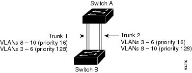
When two ports on the same switch form a loop, the switch uses the STP port priority to decide which port is enabled and which port is in a blocking state. You can set the priorities on a parallel STP trunk port so that the port carries all the traffic for a given VLAN. The trunk port with the higher priority (lower values) for a VLAN is forwarding traffic for that VLAN. The trunk port with the lower priority (higher values) for the same VLAN remains in a blocking state for that VLAN. One trunk port sends or receives all traffic for the VLAN.
Figure 7-2 shows two trunks connecting supported switches. In this example, the switches are configured as follows:
•
•
•
•
In this way, Trunk 1 carries traffic for VLANs 8 through 10, and Trunk 2 carries traffic for VLANs 3 through 6. If the active trunk fails, the trunk with the lower priority takes over and carries the traffic for all of the VLANs. No duplication of traffic occurs over any trunk port.
Figure 7-2 Load Sharing by Using STP Port Priorities
Beginning in privileged EXEC mode on Switch A, follow these steps to configure the network shown in Figure 7-2. Note that you can use any interface numbers; those shown are examples.
Follow the same steps on Switch B to configure the trunk port for Trunk 1 with a spanning-tree port priority of 16 for VLANs 8 through 10, and the configure trunk port for Trunk 2 with a spanning-tree port priority of 16 for VLANs 3 through 6.
Load Sharing Using STP Path Cost
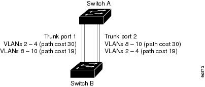
You can configure parallel trunks to share VLAN traffic by setting different path costs on a trunk and associating the path costs with different sets of VLANs, blocking different ports for different VLANs. The VLANs keep the traffic separate and maintain redundancy in the event of a lost link.
In Figure 7-3, Trunk ports 1 and 2 are configured as 100Base-T ports. These VLAN path costs are assigned:
•
•
•
•
Figure 7-3 Load-Sharing Trunks with Traffic Distributed by Path Cost
Beginning in privileged EXEC mode, follow these steps to configure the network shown in Figure 7-3:
Follow the same steps on Switch B to configure the trunk port for Trunk 1 with a path cost of 30 for VLANs 2 through 4, and configure the trunk port for Trunk 2 with a path cost of 30 for VLANs 8 through 10.