Cisco MWR 2941 Mobile Wireless Edge Router Software Configuration Guide, Release 15.0(1)MR
Configuring Ethernet Link Operations, Administration, and Maintenance

Table Of Contents

Configuring Ethernet OAM, CFM, and E-LMI

Understanding Ethernet CFM

CFM Domain

Maintenance Associations and Maintenance Points

CFM Messages

Crosscheck Function and Static Remote MEPs

SNMP Traps and Fault Alarms

Configuration Error List

CFM Version Interoperability

IP SLAs Support for CFM

Configuring Ethernet CFM

Default Ethernet CFM Configuration

Ethernet CFM Configuration Guidelines

Configuring the CFM Domain

Configuring Ethernet CFM Crosscheck

Configuring Static Remote MEP

Configuring a Port MEP

Configuring SNMP Traps

Configuring Fault Alarms

Configuring IP SLAs CFM Operation

Manually Configuring an IP SLAs CFM Probe or Jitter Operation

Configuring an IP SLAs Operation with Endpoint Discovery

Understanding CFM ITU-T Y.1731 Fault Management

Y.1731 Terminology

Alarm Indication Signals

Ethernet Remote Defect Indication

Ethernet Locked Signal

Multicast Ethernet Loopback

Configuring Y.1731 Fault Management

Default Y.1731 Configuration

Configuring ETH-AIS

Using Multicast Ethernet Loopback

Managing and Displaying Ethernet CFM Information

Understanding the Ethernet OAM Protocol

OAM Features

Discovery

Link Monitoring

Remote Failure Indication

Remote Loopback

Cisco Vendor-Specific Extensions

OAM Messages

Setting Up and Configuring Ethernet OAM

Default Ethernet OAM Configuration

Ethernet OAM Configuration Guidelines

Enabling Ethernet OAM on an Interface

Enabling Ethernet OAM Remote Loopback

Configuring Ethernet OAM Link Monitoring

Configuring Ethernet OAM Remote Failure Indications

Configuring Ethernet OAM Templates

Displaying Ethernet OAM Protocol Information

Understanding E-LMI

Configuring E-LMI

Default E-LMI Configuration

Enabling E-LMI

Customer-Edge Device Configuration

Displaying E-LMI Information

Enabling Ethernet OAM

Understanding Microwave 1+1 Hot Standby Protocol

Overview

Suspending Continuity Check Messages

HSBY Maintenance Associations

Configuring Microwave 1+1 Hot Standby Protocol

ODU Configuration Values

IDU Configuration Values

Configuring HSBY

Configuration Examples

Ethernet OAM and CFM Configuration: Example

CFM and ELMI Sample Configuration: Example

HSBY Sample Configuration: Example


Configuring Ethernet OAM, CFM, and E-LMI


Ethernet Operations, Administration, and Maintenance (OAM) is a protocol for installing, monitoring, and troubleshooting Ethernet networks to increase management capability within the context of the overall Ethernet infrastructure. The Cisco MWR 2941 router supports IEEE 802.1ag Connectivity Fault Management (CFM), Ethernet Local Management Interface (E-LMI), and IEEE 802.3ah Ethernet OAM discovery, link monitoring, remote fault detection, and remote loopback. It also supports IP Service Level Agreements (SLAs) for CFM, and ITU-T Y.1731 fault management.

This chapter provides information about configuring CFM, E-LMI, and the Ethernet OAM protocol. It defines the differences between the ratified CFM 802.1ag standard (draft 8.1) and the previous version, Cisco IOS (draft 1.0). It also includes configuration information for CFM ITU-TY.1731 fault management support in this release.


Note Release 15.0(1)MR does not support the draft 1.0 version of CFM.


For complete command and configuration information for Ethernet OAM,CFM, E-LMI, and Y.1731, see the Cisco IOS Carrier Ethernet Configuration Guide at this URL:
http://www.cisco.com/en/US/docs/ios/cether/configuration/guide/12_2sr/ce_12_2sr_book.html

For complete syntax of the commands used in this chapter, see the Cisco MWR 2941 Mobile Wireless Edge Router IOS Command Reference, Release 15.0(1)MR and the Cisco IOS Carrier Ethernet Command Reference at this URL:
http://www.cisco.com/en/US/docs/ios/cether/command/reference/ce_book.html

The Cisco MWR 2941 does not necessarily support all of the commands listed in the Cisco IOS Carrier Ethernet documentation.

This chapter contains these sections:

Understanding Ethernet CFM

Configuring Ethernet CFM

Understanding CFM ITU-T Y.1731 Fault Management

Configuring Y.1731 Fault Management

Managing and Displaying Ethernet CFM Information

Understanding the Ethernet OAM Protocol

Setting Up and Configuring Ethernet OAM

Displaying Ethernet OAM Protocol Information

Understanding E-LMI

Configuring E-LMI

Displaying E-LMI Information

Enabling Ethernet OAM

Understanding Microwave 1+1 Hot Standby Protocol

Configuring Microwave 1+1 Hot Standby Protocol

Configuration Examples

Understanding Ethernet CFM

Ethernet CFM is an end-to-end per-service-instance (per VLAN) Ethernet layer OAM protocol that includes proactive connectivity monitoring, fault verification, and fault isolation. End-to-end can be provider-edge-to-provider-edge (PE-to-PE) device or customer-edge-to-customer-edge (CE-to-CE) device. Ethernet CFM, as specified by IEEE 802.1ag, is the standard for Layer 2 ping, Layer 2 traceroute, and end-to-end connectivity check of the Ethernet network.

These sections contain conceptual information about Ethernet CFM:

CFM Domain

Maintenance Associations and Maintenance Points

CFM Messages

Crosscheck Function and Static Remote MEPs

SNMP Traps and Fault Alarms

Configuration Error List

CFM Version Interoperability

IP SLAs Support for CFM

CFM Domain

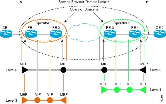
A CFM maintenance domain is a management space on a network that is owned and operated by a single entity and defined by a set of ports internal to it, but at its boundary. You assign a unique maintenance level (from 0 to 7) to define the hierarchical relationship between domains. The larger the domain, the higher the level. For example, as shown in Figure 15-1, a service-provider domain would be larger than an operator domain and might have a maintenance level of 6, while the operator domain maintenance level is 3 or 4.

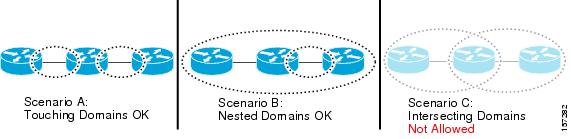
As shown in Figure 15-2, domains cannot intersect or overlap because that would require management by more than one entity, which is not allowed. Domains can touch or nest (if the outer domain has a higher maintenance level than the nested domain). Nesting domains is useful when a service provider contract with one or more operators to provide Ethernet service. Each operator has its own maintenance domain and the service provider domain is a superset of the operator domains. Maintenance levels of nesting domains should be communicated among the administrating organizations. CFM exchanges messages and performs operations on a per-domain basis.

Figure 15-1 CFM Maintenance Domains

Figure 15-2 Allowed Domain Relationships

Maintenance Associations and Maintenance Points

A maintenance association (MA) identifies a service that can be uniquely identified within the maintenance domain. The CFM protocol runs within a maintenance association.A maintenance point is a demarcation point on an interface that participates in CFM within a maintenance domain. Maintenance points drop all lower-level frames and forward all higher-level frames. There are two types of maintenance points:

Maintenance end points (MEPs) are points at the edge of the domain that define the boundaries and confine CFM messages within these boundaries. Outward facing or Down MEPs communicate through the wire side (connected to the port). Inward facing or Up MEPs communicate through the relay function side, not the wire side.


Note CFM draft 1 referred to inward and outward-facing MEPs. CFM draft 8.1 refers to up and down MEPs, respectively. This document uses the CFM 8.1 terminology for direction.


CFM draft 1 supported only up MEPs on a per-port or per-VLAN basis. CFM 802.1ag supports up and down per-VLAN MEPs, as well as port MEPs, which are untagged down MEPs that are not associated with a VLAN. Port MEPs are configured to protect a single hop and used to monitor link state through CFM. If a port MEP is not receiving continuity check messages from its peer (static remote MEP), for a specified interval, the port is put into an operational down state in which only CFM and OAM packets pass through, and all other data and control packets are dropped.

An up MEP sends and receives CFM frames through the relay function. It drops all CFM frames at its level or lower that come from the wire side, except traffic going to the down MEP. For CFM frames from the relay side, it processes the frames at its level and drops frames at a lower level. The MEP transparently forwards all CFM frames at a higher level, regardless of whether they are received from the relay or wire side. If the port on which MEP is configured is blocked by STP, the MEP can still send or receive CFM messages through the relay function. CFM runs at the provider maintenance level (UPE-to-UPE), specifically with up MEPs at the user network interface (UNI).

A down MEP sends and receives CFM frames through the wire connected to the port on which the MEP is configured. It drops all CFM frames at its level or lower that come from the relay side. For CFM frames from the wire side, it processes all CFM frames at its level and drops CFM frames at lower levels except traffic going to the other lower-level down MEP. The MEP transparently forwards all CFM frames at a higher level, regardless of whether they are received from the relay or through the wire.

Maintenance intermediate points (MIPs) are internal to a domain, not at the boundary, and respond to CFM only when triggered by traceroute and loopback messages. They forward CFM frames received from MEPs and other MIPs, drop all CFM frames at a lower level (unless MIP filtering is enabled), and forward all CFM frames at a higher level and at a lower level and regardless of whether they are received from the relay or wire side. When MIP filtering is enabled, the MIP drops CFM frames at a lower level. MIPs also catalog and forward continuity check messages (CCMs), but do not respond to them.

In the first draft of CFM, MIP filtering was always enabled. In draft 8.1, MIP filtering is disabled by default, and you can configure it to be enabled or disabled. When MIP filtering is disabled, all CFM frames are forwarded.

You can manually configure a MIP or configure the router to automatically create a MIP. You can configure a MEP without a MIP. In case of a configuration conflict, manually created MIPs take precedence over automatically created MIPs.

If port on which the MEP is configured is blocked by Spanning-Tree Protocol (STP), the MIP can receive and might respond to CFM messages from both the wire and relay side, but cannot forward any CFM messages. This differs from CFM draft 1, where STP blocked ports could not send or receive CFM messages.

CFM Messages

CFM uses standard Ethernet frames distinguished by EtherType or (for multicast messages) by MAC address. All CFM messages are confined to a maintenance domain and to a service-provider VLAN (S-VLAN). These CFM messages are supported:

Continuity Check (CC) messages—multicast heartbeat messages exchanged periodically between MEPs that allow MEPs to discover other MEPs within a domain and allow MIPs to discover MEPs. CC messages are configured to a domain or VLAN. Enter the continuity-check Ethernet service configuration command to enable CCM.

The default continuity check message (CCM) interval on the router is 10 seconds. You can set it to be 100 ms, 1 second, 1 minute, or 10 minutes by entering the continuity-check interval Ethernet service mode command. Because faster CCM rates are more CPU intensive, we do not recommend configuring a large number of MEPs running at 100 ms intervals.

Loopback messages—unicast or multicast frames transmitted by a MEP at administrator request to verify connectivity to a particular maintenance point, indicating if a destination is reachable. A loopback message is similar to an Internet Control Message Protocol (ICMP) ping message. Refer to the ping ethernet privileged EXEC command.

Traceroute messages—multicast frames transmitted by a MEP at administrator request to track the path (hop-by-hop) to a destination MEP. Traceroute messages are similar in concept to UDP traceroute messages. Refer to the traceroute ethernet privileged EXEC command.

Crosscheck Function and Static Remote MEPs

The crosscheck function is a timer-driven post-provisioning service verification between dynamically configured MEPs (using crosscheck messages) and expected MEPs (by configuration) for a service. It verifies that all endpoints of a multipoint service are operational. The crosscheck function is performed only one time and is initiated from the command-line interface (CLI).

CFM 802.1ag also supports static remote MEPs or static RMEP check. Unlike the crosscheck function, which is performed only once, configured static RMEP checks run continuously. To configure static RMEP check, enter the continuity-check static rmep Ethernet CFM service mode command.

SNMP Traps and Fault Alarms

The MEPs generate two types of SNMP traps: CC traps and crosscheck traps. Supported CC traps are MEP up, MEP down, cross-connect (a service ID does not match the VLAN), loop, and configuration error. The crosscheck traps are service up, MEP missing (an expected MEP is down), and unknown MEP.

Fault alarms are unsolicited notifications sent to alert the system administrator when CFM detects a fault. In CFM draft 1, fault alarms were sent instantaneously when detected. In CFM 802.1ag, you can configure the priority level of alarms that trigger an SNMP trap or syslog message. You can also configure a delay period before a fault alarm is sent and the time before the alarm is reset.

Configuration Error List

CFM configuration errors in CFM 802.1ag can be misconfigurations or extra configuration commands detected during MEP configuration. They can be caused by overlapping maintenance associations. For example, if you create a maintenance association with a VLAN list and a MEP on an interface, a potential leak error could occur if other maintenance associations associated with the same VLAN exist at a higher level without any MEPs configured. You can display the configuration error list, which is informational only, by entering the show ethernet cfm errors configuration privileged EXEC command.

CFM Version Interoperability

When customers upgrade their network from the Cisco CFM draft 1 to IEEE standardized 802.1ag CFM, they might not upgrade all equipment at the same time, which could result in a mix of Cisco CFM draft 1 and IEEE standardized CFM devices in the network. CFM areas are regions in a network running Cisco CFM draft 1 software. Internal area bridges are all Cisco devices running CFM draft 1, and external area bridges are devices (Cisco or third-party devices) running IEEE standardized 802.1ag CFM.

Devices at the edge of these areas perform message translation. Translation is not needed for maintenance domains that do not span different areas (that is, where CFM messages end on a port on the device) since the port can respond in the same message format as was received. However, for maintenance domains that span across two areas, the device must translate the CFM message appropriately before sending it on to the other area.


Note The Cisco MWR 2941 does not support translation between CFM draft 1.0 and IEEE standardized 802.1ag CFM.


When designing a network with CFM areas, follow these guidelines:

Whenever possible, group devices with the same CFM version together.

Minimize the number of boundaries between CFM clusters, minimizing the number of devices that must perform translation.

Never mix CFM versions on a single segment.

IP SLAs Support for CFM

The router supports CFM with IP Service Level Agreements (SLAs), which provides the ability to gather Ethernet layer network performance metrics. Available statistical measurements for the IP SLAs CFM operation include round-trip time, jitter (interpacket delay variance), and packet loss. You can schedule multiple IP SLAs operations and use Simple Network Management Protocol (SNMP) trap notifications and syslog messages for proactive threshold violation monitoring.

For more information about IP SLAs, see Chapter 41 "Configuring Cisco IOS IP SLAs Operations."

IP SLAs integration with CFM gathers Ethernet layer statistical measurements by sending and receiving Ethernet data frames between CFM MEPs. Performance is measured between the source MEP and the destination MEP. Unlike other IP SLAs operations that provide performance metrics for only the IP layer, IP SLAs with CFM provides performance metrics for Layer 2.

You can manually configure individual Ethernet ping or jitter operations. You can also configure an IP SLAs automatic Ethernet operation that queries the CFM database for all MEPs in a given maintenance domain and VLAN. The operation then automatically creates individual Ethernet ping or jitter operations based on the discovered MEPs.

Because IP SLAs is a Cisco proprietary feature, interoperability between CFM draft 1 and CFM 802.1ag is handled automatically by the router.

For more information about IP SLAs operation with CFM, see the IP SLAs for Metro-Ethernet feature module at this URL:

http://www.cisco.com/en/US/products/ps6922/products_feature_guide09186a00807d72f5.html

Configuring Ethernet CFM

Configuring Ethernet CFM requires configuring the CFM domain. You can optionally configure and enable other CFM features such as crosschecking, remote MEP, port MEPs, SNMP traps, and fault alarms. Note that some of the configuration commands and procedures differ from those used in CFM draft 1.

Default Ethernet CFM Configuration

Ethernet CFM Configuration Guidelines

Configuring the CFM Domain

Configuring Ethernet CFM Crosscheck

Configuring Static Remote MEP

Configuring a Port MEP

Configuring SNMP Traps

Configuring Fault Alarms

Configuring IP SLAs CFM Operation

Default Ethernet CFM Configuration

CFM is globally disabled.

CFM is enabled on all interfaces when CFM is globally enabled.

A port can be configured as a flow point (MIP/MEP), a transparent port, or disabled (CFM disabled). By default, ports are transparent ports until configured as MEP, MIP, or disabled.

There are no MEPs or MIPs configured.

When configuring a MEP, if you do not configure direction, the default is up (inward facing).

Ethernet CFM Configuration Guidelines

EtherChannels are not supported.

CFM is not supported on and cannot be configured on routed ports.

You cannot configure CFM on VLAN interfaces.

CFM is supported on trunk ports and access ports with these exceptions:

Trunk ports configured as MEPs must belong to allowed VLANs

Access ports configured as MEPs must belong to the native VLAN.

CFM is not supported on 802.1Q tunnel interfaces.

You cannot configure CFM on an EoMPLS port.

A REP port or FlexLink port can also be a service (VLAN) MEP or MIP, but it cannot be a port MEP.

CFM is supported on ports running STP.

You must configure a port MEP at a lower level than any service (VLAN) MEPs on an interface.

Configuring the CFM Domain

Beginning in privileged EXEC mode, follow these steps to configure the Ethernet CFM domain, configure a service to connect the domain to a VLAN, or configure a port to act as a MEP. You can also enter the optional commands to configure other parameters, such as continuity checks.


Note You do not need to enter the ethernet cfm ieee global configuration command to configure the CFM version as IEEE 802.1ag; the CFM version is always 802.1ag and the command is automatically generated when you enable CFM.


Command
Purpose

Step 1 

configure terminal

Enter global configuration mode.

Step 2 

ethernet cfm global

Globally enable Ethernet CFM on the router.

Step 3 

ethernet cfm traceroute cache [size entries | hold-time minutes]

(Optional) Configure the CFM traceroute cache. You can set a maximum cache size or hold time.

(Optional) For size, enter the cache size in number of entry lines. The range is from 1 to 4095; the default is 100 lines.

(Optional) For hold-time, enter the maximum cache hold time in minutes. The range is from 1 to 65535; the default is 100 minutes.

Step 4 

ethernet cfm mip auto-create level level-id vlan vlan-id

(Optional) Configure the router to automatically create MIPs for VLAN IDS that are not associated with specific maintenance associations at the specified level. The level range is 0 to 7.

Note Configure MIP auto-creation only for VLANs that MIPs should monitor. Configuring for all VLANs can be CPU and memory-intensive.

Step 5 

ethernet cfm mip filter

(Optional) Enable MIP filtering, which means that all CFM frames at a lower level are dropped. The default is disabled.

Step 6 

ethernet cfm domain domain-name level level-id

Define a CFM domain, set the domain level, and enter ethernet-cfm configuration mode for the domain. The maintenance level number range is 0 to 7.

Step 7 

id {mac-address domain_number | dns name | null}

(Optional) Assign a maintenance domain identifier.

mac-address domain_numberEnter the MAC address and a domain number. The number can be from 0 to 65535.

dns name—Enter a DNS name string. The name can be a maximum of 43 characters.

null—Assign no domain name.

Step 8 

service {ma-name | ma-number | vpn-id vpn} {vlan vlan-id [direction down] | port}

Define a customer service maintenance association (MA) name or number or VPN ID to be associated with the domain, a VLAN ID or port MEP, and enter ethernet-cfm-service configuration mode.

ma-name—a string of no more than 100 characters that identifies the MAID.

ma-number—a value from 0 to 65535.

vpn-id vpn—enter a VPN ID as the ma-name.

vlan vlan-id—VLAN range is from 1 to 4094. You cannot use the same VLAN ID for more than one domain at the same level.

(Optional) direction down—specify the service direction as down.

port—Configure port MEP, a down MEP that is untagged and not associated with a VLAN.

Step 9 

continuity-check

Enable sending and receiving of continuity check messages.

Step 10 

continuity-check interval value

(Optional) Set the interval at which continuity check messages are sent. The available values are 100 ms, 1 second, 10 seconds, 1 minute and 10 minutes. The default is 10 seconds.

Note Because faster CCM rates are more CPU-intensive, we do not recommend configuring a large number of MEPs running at 100 ms intervals.

Step 11 

continuity-check loss-threshold threshold-value

(Optional) Set the number of continuity check messages to be missed before declaring that an MEP is down. The range is 2 to 255; the default is 3.

Step 12 

maximum meps value

(Optional) Configure the maximum number of MEPs allowed across the network. The range is from 1 to 65535. The default is 100.

Step 13 

sender-id {chassis | none}

(Optional) Include the sender ID TLVs, attributes containing type, length, and values for neighbor devices.

chassis—Send the chassis ID (host name).

none—Do not include information in the sender ID.

Step 14 

mip auto-create [lower-mep-only | none]

(Optional) Configure auto creation of MIPs for the service.

lower-mep-only—Create a MIP only if there is a MEP for the service in another domain at the next lower active level.

none —No MIP auto-create.

Step 15 

exit

Return to ethernet-cfm configuration mode.

Step 16 

mip auto-create [lower-mep-only]

(Optional) Configure auto creation of MIPs for the domain.

lower-mep-only—Create a MIP only if there is a MEP for the service in another domain at the next lower active level.

Step 17 

mep archive-hold-time minutes

(Optional) Set the number of minutes that data from a missing maintenance end point is kept before it is purged. The range is 1 to 65535; the default is 100 minutes.

Step 18 

exit

Return to global configuration mode.

Step 19 

interface interface-id

Specify an interface to configure, and enter interface configuration mode.

Step 20 

switchport mode trunk

(Optional) Configure the port as a trunk port.

Step 21 

ethernet cfm mip level level-id

(Optional) Configure a customer level or service-provider level maintenance intermediate point (MIP) for the interface. The MIP level range is 0 to 7.

Note This step is not required if you have entered the ethernet cfm mip auto-create global configuration command or the mip auto-create ethernet-cfm or ethernet-cfm-srv configuration mode.

Step 22 

ethernet cfm mep domain domain-name mpid identifier {vlan vlan-id | port}

Configure maintenance end points for the domain, and enter Ethernet cfm mep mode.

domain domain-name—Specify the name of the created domain.

mpid identifier—Enter a maintenance end point identifier. The identifier must be unique for each VLAN (service instance). The range is 1 to 8191.

vlan vlan-id—Enter the service provider VLAN ID or IDs as a VLAN-ID (1 to 4094), a range of VLAN-IDs separated by a hyphen, or a series of VLAN IDs separated by comma.

port—Configure port MEP.

Step 23 

cos value

(Optional) Specify the class of service (CoS) value to be sent with the messages. The range is 0 to 7.

Step 24 

end

Return to privileged EXEC mode.

Step 25 

show ethernet cfm maintenance-points {local | remote}

Verify the configuration.

Step 26 

show ethernet cfm errors [configuration]

(Optional) Display the configuration error list.

Step 27 

copy running-config startup-config

(Optional) Save your entries in the configuration file.

Use the no versions of the commands to remove the configuration or return to the default configurations.

This is an example of the basic CFM configuration:

Router(config)# ethernet cfm ieee
Router(config)# ethernet cfm global
Router(config)# ethernet cfm domain abc level 3
Router(config-ecfm)# service test vlan 5
Router(config-ecfm-srv)# continuity-check
Router(config-ecfm-srv)# exit
Router(config-ecfm)# exit
Router(config)# interface gigabitethernet1/0/2
Router(config-if)# ethernet cfm mep domain abc mpid 222 vlan 5
Router(config-if-ecfm-mep)# exit

Configuring Ethernet CFM Crosscheck

Beginning in privileged EXEC mode, follow these steps to configure Ethernet CFM crosscheck:

 
Command
Purpose

Step 1 

configure terminal

Enter global configuration mode.

Step 2 

ethernet cfm mep crosscheck start-delay delay

Configure the number of seconds that the device waits for remote MEPs to come up before the crosscheck is started. The range is 1 to 65535; the default is 30 seconds.

Step 3 

ethernet cfm domain domain-name level level-id

Define a CFM domain, set the domain level, and enter ethernet-cfm configuration mode for the domain. The maintenance level number range is 0 to 7.

Step 4 

service {ma-name | ma-number | vpn-id vpn} {vlan vlan-id}

Define a customer service maintenance association name or number or VPN ID to be associated with the domain, and a VLAN ID, and enter ethernet-cfm-service configuration mode.

ma-name—a string of no more than 100 characters that identifies the MAID.

ma-number—a value from 0 to 65535.

vpn-id vpn—enter a VPN ID as the ma-name.

vlan vlan-id—VLAN range is from 1 to 4094. You cannot use the same VLAN ID for more than one domain at the same level.

Step 5 

mep mpid identifier

Define the MEP maintenance end point identifier in the domain and service. The range is 1 to 8191

Step 6 

end

Return to privileged EXEC mode.

Step 7 

ethernet cfm mep crosscheck {enable | disable} domain domain-name {vlan {vlan-id | any} | port}

Enable or disable CFM crosscheck for one or more VLANs or a port MEP in the domain.

domain domain-name—Specify the name of the created domain.

vlan {vlan-id | any}—Enter the service provider VLAN ID or IDs as a VLAN-ID (1 to 4094), a range of VLAN-IDs separated by a hyphen, or a series of VLAN IDs separated by comma. Enter any for any VLAN.

port—Identify a port MEP.

Step 8 

show ethernet cfm maintenance-points remote crosscheck

Verify the configuration.

Step 9 

show ethernet cfm errors [configuration]

Enter this command after you enable CFM crosscheck to display the results of the crosscheck operation. Enter the configuration keyword to display the configuration error list.

Step 10 

copy running-config startup-config

(Optional) Save your entries in the configuration file.

Use the no form of each command to remove a configuration or to return to the default settings.

Configuring Static Remote MEP

Beginning in privileged EXEC mode, follow these steps to configure Ethernet CFM static remote MEP:

 
Command
Purpose

Step 1 

configure terminal

Enter global configuration mode.

Step 2 

ethernet cfm domain domain-name level level-id

Define a CFM domain, set the domain level, and enter ethernet-cfm configuration mode for the domain. The maintenance level number range is 0 to 7.

Step 3 

service {ma-name | ma-num | vlan-id vlan-id | vpn-id vpn-id} [port | vlan vlan-id [direction down]]

Define a customer service maintenance association name or number or a VPN ID to be associated with the domain, and a VLAN ID or peer MEP, and enter ethernet-cfm-service configuration mode.

ma-name—a string of no more than 100 characters that identifies the MAID.

ma-number—a value from 0 to 65535.

vpn-id—enter a VPN ID as the ma-name.

Note The vpn-id keyword is not supported.

vlan vlan-id—VLAN range is from 1 to 4094. You cannot use the same VLAN ID for more than one domain at the same level.

(Optional) direction down—specify the service direction as down.

port—Configure port MEP, a down MEP that is untagged and not associated with a VLAN.

Step 4 

continuity-check

Enable sending and receiving of continuity check messages.

Step 5 

mep mpid identifier

Define the static remote maintenance end point identifier. The range is 1 to 8191

Step 6 

continuity-check static rmep

Enable checking of the incoming continuity check message from a remote MEP that is configured in the MEP list.

Step 7 

end

Return to privileged EXEC mode.

Step 8 

show ethernet cfm maintenance-points remote static

Verify the configuration.

Step 9 

show ethernet cfm errors [configuration]

Enter this command after you enable CFM crosscheck to display the results of the crosscheck operation. Enter the configuration keyword to display the configuration error list.

Step 10 

copy running-config startup-config

(Optional) Save your entries in the configuration file.

Use the no form of each command to remove a configuration or to return to the default settings.

Configuring a Port MEP

A port MEP is a down MEP that is not associated with a VLAN and that uses untagged frames to carry CFM messages. You configure port MEPs on two connected interfaces. Port MEPs are always configured at a lower domain level than native VLAN MEPs.

Beginning in privileged EXEC mode, follow these steps to configure Ethernet CFM port MEPs:

 
Command
Purpose

Step 1 

configure terminal

Enter global configuration mode.

Step 2 

ethernet cfm domain domain-name level level-id

Define a CFM domain, set the domain level, and enter ethernet-cfm configuration mode for the domain. The maintenance level number range is 0 to 7.

Step 3 

service {ma-name | ma-number | vpn-id} port

Define a customer service maintenance association name or number or VPN ID to be associated with the domain, define a port MEP, and enter ethernet-cfm-service configuration mode.

ma-name—a string of no more than 100 characters that identifies the MAID.

ma-number—a value from 0 to 65535.

vpn-id vpn—enter a VPN ID as the ma-name.

Step 4 

mep mpid identifier

Define the static remote maintenance end point identifier in the domain and service. The range is 1 to 8191

Step 5 

continuity-check

Enable sending and receiving of continuity check messages.

Step 6 

continuity-check interval value

(Optional) Set the interval at which continuity check messages are sent. The available values are 100 ms, 1 second, 10 seconds, 1 minute and 10 minutes. The default is 10 seconds.

Note Because faster CCM rates are more CPU-intensive, we do not recommend configuring a large number of MEPs running at 100 ms intervals.

Step 7 

continuity-check loss-threshold threshold-value

(Optional) Set the number of continuity check messages to be missed before declaring that an MEP is down. The range is 2 to 255; the default is 3.

Step 8 

continuity-check static rmep

Enable checking of the incoming continuity check message from a remote MEP that is configured in the MEP list.

Step 9 

exit

Return to ethernet-cfm configuration mode.

Step 10 

exit

Return to global configuration mode.

Step 11 

interface interface-id

Identify the port MEP interface and enter interface configuration mode.

Step 12 

ethernet cfm mep domain domain-name mpid identifier port

Configure the interface as a port MEP for the domain.

domain domain-name—Specify the name of the created domain.

mpid identifier—Enter a maintenance end point identifier. The identifier must be unique for each VLAN (service instance). The range is 1 to 8191.

Step 13 

end

Return to privileged EXEC mode.

Step 14 

show ethernet cfm maintenance-points remote static

Verify the configuration.

Step 15 

show ethernet cfm errors [configuration]

Enter this command after you enable CFM crosscheck to display the results of the crosscheck operation. Enter the configuration keyword to display the configuration error list.

Step 16 

copy running-config startup-config

(Optional) Save your entries in the configuration file.

Use the no form of each command to remove a configuration or to return to the default settings.

This is a sample configuration for a port MEP:

Router(config)# ethernet cfm domain abc level 3
Router(config-ecfm)# service PORTMEP port
Router(config-ecfm-srv)# mep mpid 222
Router(config-ecfm-srv)# continuity-check
Router(config-ecfm-srv)# continuity-check static rmep
Router(config-ecfm-srv)# exit
Router(config-ecfm)# exit
Router(config)# interface gigabitethernet1/0/1
Router(config-if)# ethernet cfm mep domain abc mpid 111 port
Router(config-if)# end

Configuring SNMP Traps

Beginning in privileged EXEC mode, follow these steps to configure traps for Ethernet CFM:

 
Command
Purpose

Step 1 

configure terminal

Enter global configuration mode.

Step 2 

snmp-server enable traps ethernet cfm cc [mep-up] [mep-down] [config] [loop] [cross-connect]

(Optional) Enable Ethernet CFM continuity check traps.

Step 3 

snmp-server enable traps ethernet cfm crosscheck [mep-unknown] [mep-missing] [service-up]

(Optional) Enable Ethernet CFM crosscheck traps.

Step 4 

end

Return to privileged EXEC mode.

Step 5 

show running-config

Verify your entries.

Step 6 

copy running-config startup-config

(Optional) Save your entries in the configuration file.

Use the no form of each command to remove a configuration or to return to the default settings.

Configuring Fault Alarms

Beginning in privileged EXEC mode, follow these steps to configure Ethernet CFM fault alarms. Note that you can configure fault alarms in either global configuration mode or Ethernet CFM interface MEP mode. In case of conflict, the interface MEP mode configuration takes precedence.

 
Command
Purpose

Step 1 

configure terminal

Enter global configuration mode.

Step 2 

ethernet cfm alarm notification {all | error-xcon | mac-remote-error-xcon | none | remote-error-xcon | xcon}

Globally enable Ethernet CFM fault alarm notification for the specified defects:

all—report all defects.

error-xcon—Report only error and connection defects.

mac-remote-error-xcon—Report only MAC-address, remote, error, and connection defects.

none—Report no defects.

remote-error-xcon—Report only remote, error, and connection defects.

xcon—Report only connection defects.

Step 3 

ethernet cfm alarm delay value

(Optional) Set a delay period before a CFM fault alarm is sent. The range is 2500 to 10000 milliseconds (ms). The default is 2500 ms.

Step 4 

ethernet cfm alarm reset value

(Optional) Specify the time period before the CFM fault alarm is reset. The range is 2500 to 10000 milliseconds (ms). The default is 10000 ms.

Step 5 

ethernet cfm logging alarm ieee

Configure the router to generate system logging messages for the alarms.

Step 6 

interface interface-id

(Optional) Specify an interface to configure, and enter interface configuration mode.

Step 7 

ethernet cfm mep domain domain-name mpid identifier vlan vlan-id

Configure maintenance end points for the domain, and enter ethernet cfm interface mep mode.

domain domain-name—Specify the name of the created domain.

mpid identifier—Enter a maintenance end point identifier. The identifier must be unique for each VLAN (service instance). The range is 1 to 8191.

vlan vlan-id—Enter the service provider VLAN ID or IDs as a VLAN-ID (1 to 4094), a range of VLAN-IDs separated by a hyphen, or a series of VLAN IDs separated by comma.

Step 8 

ethernet cfm alarm notification {all | error-xcon | mac-remote-error-xcon | none | remote-error-xcon | xcon}

(Optional) Enable Ethernet CFM fault alarm notification for the specified defects on the interface.

Note The Ethernet CFM interface MEP alarm configuration takes precedence over the global configuration.

Step 9 

ethernet cfm alarm {delay value | reset value}

(Optional) Set an alarm delay period or a reset period.

Note The Ethernet CFM interface MEP alarm configuration takes precedence over the global configuration.

Step 10 

end

Return to privileged EXEC mode.

Step 11 

show running-config

Verify your entries.

Step 12 

copy running-config startup-config

(Optional) Save your entries in the configuration file.

Use the no form of each command to remove a configuration or to return to the default settings.

Configuring IP SLAs CFM Operation

You can manually configure an individual IP SLAs Ethernet ping or jitter echo operation or you can configure IP SLAs Ethernet operation with endpoint discovery. You can also configure multiple operation scheduling. For accurate one-way delay statistics, the clocks on the endpoint switches must be synchronized. You can configure the endpoint switches with Network Time Protocol (NTP) so that the switches are synchronized to the same clock source.


Note You cannot enable Precision Timing Protocol (PTP) if you enable NTP. For more information about PTP, see Configuring Clocking and Timing.


For more information about configuring IP SLAs Ethernet operation, see the IP SLAs Configuration Guide, Cisco IOS Release 15.0S. For detailed information about commands for IP SLAs, see the Cisco IOS IP SLAs Command Reference.


Note The Cisco MWR 2941 does not necessarily support all of the commands listed in the Cisco IOS IP SLA documentation.


This section includes these procedures:

Manually Configuring an IP SLAs CFM Probe or Jitter Operation

Configuring an IP SLAs Operation with Endpoint Discovery

Manually Configuring an IP SLAs CFM Probe or Jitter Operation

Beginning in privileged EXEC mode, follow these steps to manually configure an IP SLAs Ethernet echo (ping) or jitter operation:

 
Command
Purpose

Step 1 

configure terminal

Enter global configuration mode.

Step 2 

ip sla operation-number

Create an IP SLAs operation, and enter IP SLAs configuration mode.

Step 3 

ethernet echo mpid identifier domain domain-name vlan vlan-id

or

ethernet jitter mpid identifier domain domain-name vlan vlan-id [interval interpacket-interval] [num-frames number-of frames transmitted]

Configure the IP SLAs operation as an echo (ping) or jitter operation, and enter IP SLAs Ethernet echo configuration mode.

Enter echo for a ping operation or jitter for a jitter operation.

For mpid identifier, enter a maintenance endpoint identifier. The identifier must be unique for each VLAN (service instance). The range is 1 to 8191.

For domain domain-name, enter the CFM domain name.

For vlan vlan-id, the VLAN range is from 1 to 4095.

(Optional—for jitter only) Enter the interval between sending of jitter packets.

(Optional—for jitter only) Enter the num-frames and the number of frames to be sent.

Step 4 

cos cos-value

(Optional) Set a class of service value for the operation.

Step 5 

frequency seconds

(Optional) Set the rate at which the IP SLAs operation repeats. The range is from 1 to 604800 seconds; the default is 60 seconds.

Step 6 

history history-parameter

(Optional) Specify parameters for gathering statistical history information for the IP SLAs operation.

Step 7 

owner owner-id

(Optional) Configure the SNMP owner of the IP SLAs operation.

Step 8 

request-data-size bytes

(Optional) Specify the protocol data size for an IP SLAs request packet. The range is from 0 to the maximum size allowed by the protocol being used; the default is 66 bytes.

Step 9 

tag text

(Optional) Create a user-specified identifier for an IP SLAs operation.

Step 10 

threshold milliseconds

(Optional) Specify the upper threshold value in milliseconds (ms0 for calculating network monitoring statistics. The range is 0 to 2147483647; the default is 5000.

Step 11 

timeout milliseconds

(Optional) Specify the amount of time in ms that the IP SLAs operation waits for a response from its request packet. The range is 0 to 604800000; the default value is 5000.

Step 12 

exit

Return to global configuration mode.

Step 13 

ip sla schedule operation-number [ageout seconds] [life {forever | seconds}] [recurring] [start-time {hh:mm {:ss} [month day | day month] | pending | now | after hh:mm:ss}]

Schedule the time parameters for the IP SLAs operation.

operation-number—Enter the IP SLAs operation number.

(Optional) ageout seconds—Enter the number of seconds to keep the operation in memory when it is not actively collecting information. The range is 0 to 2073600 seconds. The default is 0 seconds.

(Optional) life—Set the operation to run indefinitely (forever) or for a specific number of seconds. The range is from 0 to 2147483647. The default is 3600 seconds (1 hour)

(Optional) recurring—Set the probe to be automatically scheduled every day.

(Optional) start-time—Enter the time for the operation to begin collecting information:

To start at a specific time, enter the hour, minute, second (in 24-hour notation), and day of the month.

Enter pending to select no information collection until a start time is selected.

Enter now to start the operation immediately.

Enter after hh:mm:ss to show that the operation should start after the entered time has elapsed.

Step 14 

end

Return to privileged EXEC mode.

Step 15 

show ip sla configuration [operation-number]

Show the configured IP SLAs operation.

Step 16 

copy running-config startup-config

(Optional) Save your entries in the configuration file.

To remove an IP SLAs operation, enter the no ip sla operation-number global configuration command.

Configuring an IP SLAs Operation with Endpoint Discovery

Beginning in privileged EXEC mode, follow these steps to use IP SLAs to automatically discover the CFM endpoints for a domain and VLAN ID. You can configure ping or jitter operations to the discovered endpoints.

 
Command
Purpose

Step 1 

configure terminal

Enter global configuration mode.

Step 2 

ip sla ethernet-monitor operation-number

Begin configuration of an IP SLAs automatic Ethernet operation, and enter IP SLAs Ethernet monitor configuration mode.

Step 3 

type echo domain domain-name vlan vlan-id [exclude-mpids mp-ids]

or

type jitter domain domain-name vlan vlan-id [exclude-mpids mp-ids] [interval interpacket-interval] [num-frames number-of frames transmitted]

Configure the automatic Ethernet operation to create echo (ping) or jitter operation and enter IP SLAs Ethernet echo configuration mode.

Enter type echo for a ping operation or type jitter for a jitter operation.

For mpid identifier, enter a maintenance endpoint identifier. The range is 1 to 8191.

For domain domain-name, enter the CFM domain name.

For vlan vlan-id, the VLAN range is from 1 to 4095.

(Optional) Enter exclude-mpids mp-ids to exclude the specified maintenance endpoint identifiers.

(Optional—for jitter only) Enter the interval between sending of jitter packets.

(Optional—for jitter only) Enter the num-frames and the number of frames to be sent.

Step 4 

cos cos-value

(Optional) Set a class of service value for the operation.

Before configuring the cos parameter, you must globally enable QoS by entering the mls qos global configuration command.

Step 5 

owner owner-id

(Optional) Configure the SNMP owner of the IP SLAs operation.

Step 6 

request-data-size bytes

(Optional) Specify the protocol data size for an IP SLAs request packet. The range is from 0 to the maximum size allowed by the protocol being used; the default is 66 bytes.

Step 7 

tag text

(Optional) Create a user-specified identifier for an IP SLAs operation.

Step 8 

threshold milliseconds

(Optional) Specify the upper threshold value in milliseconds for calculating network monitoring statistics. The range is 0 to 2147483647; the default is 5000.

Step 9 

timeout milliseconds

(Optional) Specify the amount of time in milliseconds that the IP SLAs operation waits for a response from its request packet. The range is 0 to 604800000; the default value is 5000.

Step 10 

exit

Return to global configuration mode.

Step 11 

ip sla schedule operation-number [ageout seconds] [life {forever | seconds}] [recurring] [start-time {hh:mm {:ss} [month day | day month] | pending | now | after hh:mm:ss}]

Schedule the time parameters for the IP SLAs operation.

operation-number—Enter the IP SLAs operation number.

(Optional) ageout seconds—Enter the number of seconds to keep the operation in memory when it is not actively collecting information. The range is 0 to 2073600 seconds. The default is 0 seconds.

(Optional) life—Set the operation to run indefinitely (forever) or for a specific number of seconds. The range is from 0 to 2147483647. The default is 3600 seconds (1 hour)

(Optional) recurring—Set the probe to be automatically scheduled every day.

(Optional) start-time—Enter the time for the operation to begin collecting information:

To start at a specific time, enter the hour, minute, second (in 24-hour notation), and day of the month.

Enter pending to select no information collection until a start time is selected.

Enter now to start the operation immediately.

Enter after hh:mm:ss to show that the operation should start after the entered time has elapsed.

Step 12 

end

Return to privileged EXEC mode.

Step 13 

show ip sla configuration [operation-number]

Show the configured IP SLAs operation.

Step 14 

copy running-config startup-config

(Optional) Save your entries in the configuration file.

To remove an IP SLAs operation, enter the no ip sla operation-number global configuration command.

Understanding CFM ITU-T Y.1731 Fault Management

The ITU-T Y.1731 feature provides new CFM functionality for fault and performance management for service providers in large network. The router supports Ethernet Alarm Indication Signal (ETH-AIS), Ethernet Remote Defect Indication (ETH-RDI), and Ethernet Multicast Loopback Message (MCAST-LBM) functionality for fault detection, verification, and isolation.

Y.1731 Terminology

Alarm Indication Signals

Ethernet Remote Defect Indication

Ethernet Locked Signal

Multicast Ethernet Loopback

Y.1731 Terminology

Server MEP—the combination of the server layer termination function and server or Ethernet adaptation layer termination function or server or Ethernet adaptation function, where the server layer termination function is expected to run OAM mechanisms specific to the server layer. The supported mechanisms are link up, link down, and 802.3ah.

Server layer—a virtual MEP layer capable of detecting fault conditions.

Defect conditions:

Loss of continuity (LOC): the MEP stopped receiving CCM frames from a peer MEP

Mismerge: the MEP received a CCM frame with a correct maintenance level (matching the MEP level) but an incorrect maintenance ID.

Unexpected MEP: the MEP received a CCM frame with the correct maintenance level (matching the MEP's level) and correct maintenance ID, but an unexpected MEP ID.

Unexpected maintenance level: the MEP received a CCM frame with an incorrect maintenance level.

Unexpected period: the MEP received a CCM frame with a correct maintenance level, a correct maintenance ID, a correct MEP ID, but a different transmission period field.

Signal fail—the MEP declares a signal fail condition when it detects a defect condition.

Alarm Indication Signal (AIS) condition—the MEP received an AIS frame.

Remote Defect Indication (RDI) condition—The MEP received a CCM frame with the RDI field set.

Locked Signal (LCK) condition—The MEP received an LCK frame.

Alarm Indication Signals

The Ethernet Alarm Signal function (ETH-AIS) is used to suppress alarms after defects are detected at the server (sub) layer, which is a virtual MEP layer capable of detecting fault conditions. A fault condition could be a signal fail condition, an AIS condition, or a LCK condition.


Note Although the configuration is allowed, you should not configure AIS in networks running STP. An STP configuration might cause AIS interruption or redirection.


When a MEP or a service MEP (SMEP) detects a connectivity fault at a specific maintenance association level, it multicasts AIS frames in the direction away from the detected failure at the client maintenance association level. The frequency of AIS frame transmission is based on the AIS transmission period. The first AIS frame is always sent immediately following the detection of the defect condition. We recommend a transition period of 1 second in a network of only a few VLANs to ensure that the first AIS frame is sent immediately following error detection. We recommend a 60-second interval in a network of multiple (up to 4094) VLANs to prevent stressing the network with 1-second transmissions.

A MEP that receives a frame with ETH-AIS information cannot determine the specific server with the defect condition or the set of peer MEPs for which it should suppress alarms. Therefore, it suppresses alarms for all peer MEPs, whether or not they are connected.

When a MEP receives an AIS frame, it examines it to be sure that the Maintenance Entity Group (MEG) level matches its own MEG and then detects the AIS default condition. (A MEG is Y.1731 terminology for maintenance association in 802.1ag.) After this detection, if no AIS frames are received for an interval of 3.5 times the AIS transmission period, the MEP clears the AIS defect condition. For example, if the AIS timer is set for 60 seconds, the AIS timer period expires after 3.5 times 60, or 210 seconds.

The AIS condition is terminated when a valid CCM is received with all error conditions cleared or when the AIS period timer expires (the default time is 60 seconds).

Ethernet Remote Defect Indication

When Ethernet OAM continuity check (ETH-CC) transmission is enabled, the Ethernet Remote Defect Indication (ETH-RDI) function uses a bit in the CFM CC message to communicate defect conditions to the MEP peers. For ETH-RDI functionality, you must configure the MEP MEG level, the ETH-CC transmission period, and the ETH-CC frame priority. ETH-RDI does not require any MIP configuration.

When a MEP receives frames with ETH-RDI information, it determines that its peer MEP has encountered a defect condition and sets the RDI files in the CCM frames for the duration of the defect condition. When the defect condition clears, the MEP clears the RDI field.

When a MEP receives a CCM frame, it examines it to ensure that its MEG level is the same and if the RDI field is set, it detects an RDI condition. For point-to-point Ethernet connections, a MEP can clear the RDI condition when it receives the first frame from its peer MEP with the RDI field cleared. However, for multipoint Ethernet connectivity, the MEP cannot determine the associated subset of peer MEPs with which the sending MEP has seen the defect condition. It can clear the RDI condition after it receives CCM frames with the RDI field cleared from its entire list of peer MEPs.

Ethernet Locked Signal


Note Ethernet locked signal is not supported in Release 15.0(1)MR.


The Ethernet Locked Signal (ETH-LCK) function communicates the administrative locking of a server MEP and interruption of data traffic being forwarded to the MEP expecting the traffic. A MEP that receives frames with ETH-LCK information can differentiate between a defect condition and an administrative locking. ETH-LCK relies on loopback information (local and remote). The default timer for ETH-LCK is 60 seconds and the default level is the MIP level.

When a MEP is administratively locked, it sends LCK frames in a direction opposite to its peer MEPs, based on the LCK transmission period, which is the same as the AIS transmission period. The first LCK frame is sent immediately following the administrative or diagnostic action.

A MEP receiving a LCK frame verifies that the maintenance level matches its configured maintenance level, and detects a LCK condition. When no LCK frames are received for an interval of 3.5 times the LCK transmission period, the MEP clears the LCK condition.

Multicast Ethernet Loopback

The multicast Ethernet loopback (ETH-LB) function verifies bidirectional connectivity of a MEP with its peer MEPs and is an on-demand OAM function. When the feature is invoked on a MEP by entering the ping privileged EXEC command, the MEP sends a multicast frame with ETH-LB request information to peer MEPs in the same MEG. The MEP expects to receive a unicast frame with ETH-LB reply information from its peer MEPs within a specified time period. A MEP receiving a multicast frame with ETH-LB request information validates the frame and transmits a frame with reply information.

To configure multicast ETH-LB, you configure the MEG level of the MEP and the priority of the multicast frames with ETH-LB requests. Multicast frames with ETH-LB request information are always marked as drop ineligible. No MIP configuration is required.

The MEP sends multicast LB message frames on an on-demand basis. After sending a multicast LBM frame, the MEP expects to receive LB reply frames within 5 seconds.

When a MEP receives a valid LBM frame, it generates an LB reply frame and sends it to the requested MEP after a random delay in the range of 0 to 1 second. The validity of the frame is determined on its having the correct MEG level.

When a MEP sends a multicast LBM frame and receives an LB reply frame within 5 seconds, the LB reply frame is valid.

Configuring Y.1731 Fault Management

To configure Y.1731 fault management, you must enable CFM and configure MIPs on the participating interfaces. AIS messages are generated only on interfaces with a configured MIP.

Default Y.1731 Configuration

Configuring ETH-AIS

Using Multicast Ethernet Loopback

Default Y.1731 Configuration

ETH-AIS is enabled by default when CFM is enabled.

When you configure ETH-AIS, you must configure CFM before ETH-AIS is operational.

ETH-RDI is set automatically when continuity check messages are enabled.

Configuring ETH-AIS

Beginning in privileged EXEC mode, follow these steps to configure Ethernet AIS on the router:

 
Command
Purpose

Step 1 

configure terminal

Enter global configuration mode.

Step 2 

ethernet cfm ais link-status global

Configure AIS-specific SMEP commands by entering config-ais-link-cfm mode.

Step 3 

level level-id

or

disable

Configure the maintenance level for sending AIS frames transmitted by the SMEP. The range is 0 to 7.

or

Disable generation of ETH-AIS frames.

Step 4 

period value

Configure the SMEP AIS transmission period interval. Allowable values are 1 second or 60 seconds.

Step 5 

exit

Return to global configuration mode.

Step 6 

ethernet cfm domain domain-name level level-id

Define a CFM domain, set the domain level, and enter ethernet-cfm configuration mode for the domain. The maintenance level number range is 0 to 7.

Step 7 

service {ma-name | ma-number | vpn-id vpn} {vlan vlan-id [direction down] | port}

Define a customer service maintenance association (MA) name or number to be associated with the domain, or a VLAN ID or VPN-ID, and enter ethernet-cfm-service configuration mode.

ma-name—a string of no more than 100 characters that identifies the MAID.

ma-number—a value from 0 to 65535.

vpn-id—enter a VPN ID as the ma-name.

vlan vlan-id—VLAN range is from 1 to 4094. You cannot use the same VLAN ID for more than one domain at the same level.

(Optional) direction down—specify the service direction as down.

port—Configure port MEP, a down MEP that is untagged and not associated with a VLAN.

Step 8 

ais level level-id

(Optional) Configure the maintenance level for sending AIS frames transmitted by the MEP. The range is 0 to 7.

Step 9 

ais period value

(Optional) Configure the MEP AIS transmission period interval. Allowable values are 1 second or 60 seconds.

Step 10 

ais expiry-threshold value

(Optional) Set the expiring threshold for the MA as an integer. The range is 2 to 255. The default is 3.5.

Step 11 

no ais suppress-alarms

(Optional) Override the suppression of redundant alarms when the MEP goes into an AIS defect condition after receiving an AIS message.

Step 12 

exit

Return to ethernet-cfm configuration mode.

Step 13 

exit

Return to global configuration mode.

Step 14 

interface interface-id

Specify an interface ID, and enter interface configuration mode.

Step 15 

[no] ethernet cfm ais link-status

Enable or disable sending AIS frames from the SMEP on the interface.

Step 16 

ethernet cfm ais link-status period value

Configure the ETH-AIS transmission period generated by the SMEP on the interface. Allowable values are 1 second or 60 seconds.

Step 17 

ethernet cfm ais link-status level level-id

Configure the maintenance level for sending AIS frames transmitted by the SMEP on the interface. The range is 0 to 7.

Step 18 

end

Return to privileged EXEC mode.

Step 19 

show ethernet cfm smep [interface interface-id]

Verify the configuration.

Step 20 

show ethernet cfm error

Display received ETH-AIS frames and other errors.

Step 21 

copy running-config startup-config

(Optional) Save your entries in the configuration file.

Use the no form of the commands to return to the default configuration or to remove a configuration. To disable the generation of ETH-AIS frames, enter the disable config-ais-link-cfm mode command.

This is an example of the output from the show ethernet cfm smep command when Ethernet AIS has been enabled:

Router# show ethernet cfm smep
SMEP Settings:
--------------
Interface: GigabitEthernet1/0/3
LCK-Status: Enabled
LCK Period: 60000 (ms)
Level to transmit LCK: Default
AIS-Status: Enabled
AIS Period: 60000 (ms)
Level to transmit AIS: Default
Defect Condition: AIS

Using Multicast Ethernet Loopback

You can use the ping privileged EXEC command to verify bidirectional connectivity of a MEP, as in this example:

Router# ping ethernet multicast domain CD vlan 10
Type escape sequence to abort.
Sending 5 Ethernet CFM loopback messages to 0180.c200.0037, timeout is 5 seconds:
Reply to Multicast request via interface FastEthernet1/0/3, from 001a.a17e.f880, 8 ms
Total Loopback Responses received: 1

Managing and Displaying Ethernet CFM Information

You can use the privileged EXEC commands in these tables to clear Ethernet CFM information.

Table 1 Clearing CFM Information  

Command
Purpose

clear ethernet cfm ais domain domain-name mpid id {vlan vlan-id | port}

Clear MEPs with matching domain and VLAN ID out of AIS defect condition.

clear ethernet cfm ais link-status interface interface-id

Clear a SMEP out of AIS defect condition.

clear ethernet cfm error

Clear all CFM error conditions, including AIS.


You can use the privileged EXEC commands in Table 15-2 to display Ethernet CFM information.

Table 15-2 Displaying CFM Information  

Command
Purpose

show ethernet cfm domain [brief]

Displays CFM domain information or brief domain information.

show ethernet cfm errors [configuration | domain-id]

Displays CFM continuity check error conditions logged on a device since it was last reset or the log was last cleared. When CFM crosscheck is enabled, displays the results of the CFM crosscheck operation.

show ethernet cfm maintenance-points local [detail | domain | interface | level | mep | mip]

Displays maintenance points configured on a device.

show ethernet cfm maintenance-points remote [crosscheck | detail | domain | static]

Displays information about a remote maintenance point domains or levels or details in the CFM database.

show ethernet cfm mpdb

Displays information about entries in the MIP continuity-check database.

show ethernet cfm smep [interface interface-id]

Displays Ethernet CFM SMEP information.

show ethernet cfm traceroute-cache

Displays the contents of the traceroute cache.

show platform cfm

Displays platform-independent CFM information.


This is an example of output from the show ethernet cfm domain brief command:

Router# show ethernet cfm domain brief
Domain Name                              Index Level Services Archive(min)
level5                                       1     5        1     100
level3                                       2     3        1     100
test                                         3     3        3     100
name                                         4     3        1     100
test1                                        5     2        1     100
lck                                          6     1        1     100Total Services : 1

This is an example of output from the show ethernet cfm errors command:

Router# show ethernet cfm errors
--------------------------------------------------------------------------------
MPID Domain Id                                   Mac Address     Type   Id  Lvl
     MAName                                      Reason                 Age
--------------------------------------------------------------------------------
6307 level3                                      0021.d7ee.fe80  Vlan   7    3
     vlan7                                       Receive RDI            5s

This is an example of output from the show ethernet cfm maintenance-points local detail command:

Router# show ethernet cfm maintenance-points local detail
Local MEPs:
----------
MPID: 7307
DomainName: level3
Level: 3
Direction: Up
Vlan: 7
Interface: Gi0/3
CC-Status: Enabled
CC Loss Threshold: 3
MAC: 0021.d7ef.0700
LCK-Status: Enabled
LCK Period: 60000(ms)
LCK Expiry Threshold: 3.5
Level to transmit LCK: Default
Defect Condition: No Defect
presentRDI: FALSE
AIS-Status: Enabled
AIS Period: 60000(ms)
AIS Expiry Threshold: 3.5
Level to transmit AIS: Default
Suppress Alarm configuration: Enabled
Suppressing Alarms: No
MIP Settings:
-------------
Local MIPs:
* = MIP Manually Configured
------------------------------------------------------------------------------
 Level Port           MacAddress     SrvcInst   Type    Id
------------------------------------------------------------------------------
*5     Gi0/3          0021.d7ef.0700 N/A        Vlan    2,7

This is an example of output from the show ethernet cfm traceroute command:

Router# show ethernet cfm traceroute
Current Cache-size: 0 Hops
Max Cache-size: 100 Hops
Hold-time: 100 Minutes

You can use the privileged EXEC commands in Table 15-3 to display IP SLAs Ethernet CFM information.

Table 15-3 Displaying IP SLAs CFM Information

Command
Purpose

show ip sla configuration [entry-number]

Displays configuration values including all defaults for all IP SLAs operations or a specific operation.

show ip sla ethernet-monitor configuration [entry-number]

Displays the configuration of the IP SLAs automatic Ethernet operation.

show ip sla statistics [entry-number | aggregated | details]

Display current or aggregated operational status and statistics.


Understanding the Ethernet OAM Protocol

The Ethernet OAM protocol for installing, monitoring, and troubleshooting Metro Ethernet networks and Ethernet WANs relies on an optional sublayer in the data link layer of the OSI model. Normal link operation does not require Ethernet OAM. You can implement Ethernet OAM on any full-duplex point-to-point or emulated point-to-point Ethernet link for a network or part of a network (specified interfaces).

OAM frames, called OAM protocol data units (OAM PDUs) use the slow protocol destination MAC address 0180.c200.0002. They are intercepted by the MAC sublayer and cannot propagate beyond a single hop within an Ethernet network. Ethernet OAM is a relatively slow protocol, with a maximum transmission rate of 10 frames per second, resulting in minor impact to normal operations. However, when you enable link monitoring, because the CPU must poll error counters frequently, the number of required CPU cycles is proportional to the number of interfaces that must be polled.

Ethernet OAM has two major components:

The OAM client establishes and manages Ethernet OAM on a link and enables and configures the OAM sublayer. During the OAM discovery phase, the OAM client monitors OAM PDUs received from the remote peer and enables OAM functionality. After the discovery phase, it manages the rules of response to OAM PDUs and the OAM remote loopback mode.

The OAM sublayer presents two standard IEEE 802.3 MAC service interfaces facing the superior and inferior MAC sublayers. It provides a dedicated interface for the OAM client to pass OAM control information and PDUs to and from the client. It includes these components:

The control block provides the interface between the OAM client and other OAM sublayer internal blocks.

The multiplexer manages frames from the MAC client, the control block, and the parser and passes OAM PDUs from the control block and loopback frames from the parser to the subordinate layer.

The parser classifies frames as OAM PDUs, MAC client frames, or loopback frames and sends them to the appropriate entity: OAM PDUs to the control block, MAC client frames to the superior sublayer, and loopback frames to the multiplexer.

OAM Features

These OAM features are defined by IEEE 802.3ah:

Discovery

Link Monitoring

Remote Failure Indication

Remote Loopback

Discovery

Discovery is the first phase of Ethernet OAM and it identifies the devices in the network and their OAM capabilities. Discovery uses information OAM PDUs. During the discovery phase, the following information is advertised within periodic information OAM PDUs:

OAM mode—Conveyed to the remote OAM entity. The mode can be either active or passive and can be used to determine device functionality.

OAM configuration (capabilities)—Advertises the capabilities of the local OAM entity. With this information a peer can determine what functions are supported and accessible; for example, loopback capability.

OAM PDU configuration—Includes the maximum OAM PDU size for receipt and delivery. This information along with the rate limiting of 10 frames per second can be used to limit the bandwidth allocated to OAM traffic.

Platform identity—A combination of an organization unique identifier (OUI) and 32-bits of vendor-specific information. OUI allocation, controlled by the IEEE, is typically the first three bytes of a MAC address.

Discovery includes an optional phase in which the local station can accept or reject the configuration of the peer OAM entity. For example, a node may require that its partner support loopback capability to be accepted into the management network. These policy decisions may be implemented as vendor-specific extensions.

Link Monitoring

Link monitoring in Ethernet OAM detects and indicates link faults under a variety of conditions. Link monitoring uses the event notification OAM PDU and sends events to the remote OAM entity when there are problems detected on the link. The error events include the following:

Error Symbol Period (error symbols per second)—The number of symbol errors that occurred during a specified period exceeded a threshold. These errors are coding symbol errors.

Error Frame (error frames per second)—The number of frame errors detected during a specified period exceeded a threshold.

Error Frame Period (error frames per n frames)—The number of frame errors within the last n frames has exceeded a threshold.

Error Frame Seconds Summary (error seconds per m seconds)—The number of error seconds (1-second intervals with at least one frame error) within the last m seconds has exceeded a threshold.

Since IEEE 802.3ah OAM does not provide a guaranteed delivery of any OAM PDU, the event notification OAM PDU may be sent multiple times to reduce the probability of a lost notification. A sequence number is used to recognize duplicate events.

Remote Failure Indication

Faults in Ethernet connectivity that are caused by slowly deteriorating quality are difficult to detect. Ethernet OAM provides a mechanism for an OAM entity to convey these failure conditions to its peer via specific flags in the OAM PDU. The following failure conditions can be communicated:

Link Fault—Loss of signal is detected by the receiver; for instance, the peer's laser is malfunctioning. A link fault is sent once per second in the information OAM PDU. Link fault applies only when the physical sublayer is capable of independently transmitting and receiving signals.

Dying Gasp—An unrecoverable condition has occurred; for example, a power failure. This type of condition is vendor specific. A notification about the condition may be sent immediately and continuously.

Critical Event—An unspecified critical event has occurred. This type of event is vendor specific. A critical event may be sent immediately and continuously.

Remote Loopback

An OAM entity can put its remote peer into loopback mode using the loopback control OAM PDU. Loopback mode helps an administrator ensure the quality of links during installation or when troubleshooting. In loopback mode, every frame received is transmitted back on the same port except for OAM PDUs and pause frames. The periodic exchange of OAM PDUs must continue during the loopback state to maintain the OAM session.

The loopback command is acknowledged by responding with an information OAM PDU with the loopback state indicated in the state field. This acknowledgement allows an administrator, for example, to estimate if a network segment can satisfy a service-level agreement. Acknowledgement makes it possible to test delay, jitter, and throughput.

When an interface is set to the remote loopback mode the interface no longer participates in any other Layer 2 or Layer 3 protocols; for example Spanning Tree Protocol (STP) or Open Shortest Path First (OSPF). The reason is that when two connected ports are in a loopback session, no frames other than the OAM PDUs are sent to the CPU for software processing. The non-OAM PDU frames are either looped back at the MAC level or discarded at the MAC level.

From a user's perspective, an interface in loopback mode is in a link-up state.

Cisco Vendor-Specific Extensions

Ethernet OAM allows vendors to extend the protocol by allowing them to create their own type-length-value (TLV) fields.

OAM Messages

Ethernet OAM messages or OAM PDUs are standard length, untagged Ethernet frames within the normal frame length bounds of 64 to 1518 bytes. The maximum OAM PDU frame size exchanged between two peers is negotiated during the discovery phase.

OAM PDUs always have the destination address of slow protocols (0180.c200.0002) and an Ethertype of 8809. OAM PDUs do not go beyond a single hop and have a hard-set maximum transmission rate of 10 OAM PDUs per second. Some OAM PDU types may be transmitted multiple times to increase the likelihood that they will be successfully received on a deteriorating link.

Four types of OAM messages are supported:

Information OAM PDU—A variable-length OAM PDU that is used for discovery. This OAM PDU includes local, remote, and organization-specific information.

Event notification OAM PDU—A variable-length OAM PDU that is used for link monitoring. This type of OAM PDU may be transmitted multiple times to increase the chance of a successful receipt; for example, in the case of high-bit errors. Event notification OAM PDUs also may include a time stamp when generated.

Loopback control OAM PDU—An OAM PDU fixed at 64 bytes in length that is used to enable or disable the remote loopback command.

Vendor-specific OAM PDU—A variable-length OAM PDU that allows the addition of vendor-specific extensions to OAM.

For instructions on how to configure Ethernet Link OAM, see Setting Up and Configuring Ethernet OAM.

Setting Up and Configuring Ethernet OAM

This section includes this information:

Default Ethernet OAM Configuration

Ethernet OAM Configuration Guidelines

Enabling Ethernet OAM on an Interface

Enabling Ethernet OAM Remote Loopback

Configuring Ethernet OAM Link Monitoring

Configuring Ethernet OAM Remote Failure Indications

Configuring Ethernet OAM Templates

Default Ethernet OAM Configuration

Ethernet OAM is disabled on all interfaces.

When Ethernet OAM is enabled on an interface, link monitoring is automatically turned on.

Remote loopback is disabled.

No Ethernet OAM templates are configured.

Ethernet OAM Configuration Guidelines

Follow these guidelines when configuring Ethernet OAM:

The router does not support monitoring of egress frames sent with cyclic redundancy code (CDC) errors. The ethernet oam link-monitor transmit crc interface-configuration or template-configuration commands are visible but are not supported on the router. The commands are accepted, but are not applied to an interface.

For a remote failure indication, the router does not generate Link Fault or Critical Event OAM PDUs. However, if these PDUs are received from a link partner, they are processed. The router supports generating and receiving Dying Gasp OAM PDUs when Ethernet OAM is disabled, the interface is shut down, the interface enters the error-disabled state, or the router is reloading. It can respond to, but not generate, Dying Gasp PDUs based on loss of power.

Enabling Ethernet OAM on an Interface

Beginning in privileged EXEC mode, follow these steps to enable Ethernet OAM on an interface:

 
Command
Purpose

Step 1 

configure terminal

Enter global configuration mode.

Step 2 

interface interface-id

Define an interface to configure as an EOM interface, and enter interface configuration mode.

Step 3 

ethernet oam

Enable Ethernet OAM on the interface.

Step 4 

ethernet oam [max-rate oampdus | min-rate seconds | mode {active | passive} | timeout seconds]

You can configure these optional OAM parameters:

(Optional) Enter max-rate oampdus to configure the maximum number of OAM PDUs sent per second. The range is from 1 to 10.

(Optional) Enter min-rate seconds to configure the minimum transmission rate in seconds when one OAM PDU is sent per second. The range is from 1 to 10.

(Optional) Enter mode active to set OAM client mode to active.

(Optional) Enter mode passive to set OAM client mode to passive.

Note When Ethernet OAM mode is enabled on two interfaces passing traffic, at least one must be in the active mode.

(Optional) Enter timeout seconds to set a time for OAM client timeout. The range is from 2 to 30.

Step 5 

end

Return to privileged EXEC mode.

Step 6 

show ethernet oam status [interface interface-id]

Verify the configuration.

Step 7 

copy running-config startup-config

(Optional) Save your entries in the configuration file.

Enter the no ethernet oam interface configuration command to disable Ethernet OAM on the interface.

Enabling Ethernet OAM Remote Loopback

You must enable Ethernet OAM remote loopback on an interface for the local OAM client to initiate OAM remote loopback operations. Changing this setting causes the local OAM client to exchange configuration information with its remote peer. Remote loopback is disabled by default.

Remote loopback has these limitations:

Internet Group Management Protocol (IGMP) packets are not looped back.

If dynamic ARP inspection is enabled, ARP or reverse ARP packets are not looped or dropped.

Beginning in privileged EXEC mode, follow these steps to enable Ethernet OAM remote loopback on an interface:

 
Command
Purpose

Step 1 

configure terminal

Enter global configuration mode.

Step 2 

interface interface-id

Define an interface to configure as an EOM interface, and enter interface configuration mode.

Step 3 

ethernet oam remote-loopback {supported | timeout seconds}

Enable Ethernet remote loopback on the interface or set a loopback timeout period.

Enter supported to enable remote loopback.

Enter timeout seconds to set a remote loopback timeout period. The range is from 1 to 10 seconds.

Step 4 

end

Return to privileged EXEC mode.

Step 5 

ethernet oam remote-loopback {start | stop} {interface interface-id}

Turn on or turn off Ethernet OAM remote loopback on an interface.

Step 6 

show ethernet oam status [interface interface-id]

Verify the configuration.

Step 7 

copy running-config startup-config

(Optional) Save your entries in the configuration file.

Use the no ethernet oam remote-loopback {supported | timeout} interface configuration command to disable remote loopback support or remove the timeout setting.

Configuring Ethernet OAM Link Monitoring

You can configure high and low thresholds for link-monitoring features. If no high threshold is configured, the default is none —no high threshold is set. If you do not set a low threshold, it defaults to a value lower than the high threshold.

Beginning in privileged EXEC mode, follow these steps to configure Ethernet OAM link monitoring on an interface:

 
Command
Purpose

Step 1 

configure terminal

Enter global configuration mode.

Step 2 

interface interface-id

Define an interface, and enter interface configuration mode.

Step 3 

ethernet oam link-monitor supported

Enable the interface to support link monitoring. This is the default.

You need to enter this command only if it has been disabled by previously entering the no ethernet oam link-monitor supported command.

Step 4 

ethernet oam link-monitor high-threshold action {error-disable-interface | failover}

Use the ethernet oam link-monitor high-threshold command to configure an error-disable function on the Ethernet OAM interface when a high threshold for an error is exceeded.

Note Release 15.0(1)MR does not support the failover keyword.

Step 5 

ethernet oam link-monitor symbol-period {threshold {high {high symbols | none} | low {low-symbols}} | window symbols}

Note Repeat this step to configure both high and low thresholds.

(Optional) Configure high and low thresholds for an error-symbol period that trigger an error-symbol period link event.

Enter threshold high high-symbols to set a high threshold in number of symbols. The range is 1 to 65535. The default is none.

Enter threshold high none to disable the high threshold if it was set. This is the default.

Enter threshold low low-symbols to set a low threshold in number of symbols. The range is 0 to 65535. It must be lower than the high threshold.

Enter window symbols to set the window size (in number of symbols) of the polling period. The range is 1 to 65535 symbols.

Step 6 

ethernet oam link-monitor frame {threshold {high {high-frames | none} | low {low-frames}} | window milliseconds}

Note Repeat this step to configure both high and low thresholds.

(Optional) Configure high and low thresholds for error frames that trigger an error-frame link event.

Enter threshold high high-frames to set a high threshold in number of frames. The range is 1 to 65535. The default is none.

Enter threshold high none to disable the high threshold if it was set. This is the default.

Enter threshold low low-frames to set a low threshold in number of frames. The range is 0 to 65535. The default is 1.

Enter window milliseconds to set the a window and period of time during which error frames are counted. The range is 10 to 600 and represents the number of milliseconds in multiples of 100. The default is 100.

Step 7 

ethernet oam link-monitor frame-period {threshold {high {high-frames | none} | low {low-frames}} | window frames}

Note Repeat this step to configure both high and low thresholds.

(Optional) Configure high and low thresholds for the error-frame period that triggers an error-frame-period link event.

Enter threshold high high-frames to set a high threshold in number of frames. The range is 1 to 65535. The default is none.

Enter threshold high none to disable the high threshold if it was set. This is the default.

Enter threshold low low-frames to set a low threshold in number of frames. The range is 0 to 65535. The default is 1.

Enter window frames to set the a polling window size in number of frames. The range is 1 to 65535; each value is a multiple of 10000 frames. The default is 1000.

Step 8 

ethernet oam link-monitor frame-seconds {threshold {high {high-frames | none} | low {low-frames}} | window milliseconds}

Note Repeat this step to configure both high and low thresholds.

(Optional) Configure high and low thresholds for the frame-seconds error that triggers an error-frame-seconds link event.

Enter threshold high high-frames to set a high error frame-seconds threshold in number of seconds. The range is 1 to 900. The default is none.

Enter threshold high none to disable the high threshold if it was set. This is the default.

Enter threshold low low-frames to set a low threshold in number of frames. The range is 1 to 900. The default is 1.

Enter window frames to set the a polling window size in number of milliseconds. The range is 100 to 9000; each value is a multiple of 100 milliseconds. The default is 1000.

Step 9 

ethernet oam link-monitor receive-crc {threshold {high {high-frames | none} | low {low-frames}} | window milliseconds}

Note Repeat this step to configure both high and low thresholds.

(Optional) Configure thresholds for monitoring ingress frames received with cyclic redundancy code (CRC) errors for a period of time.

Enter threshold high high-frames to set a high threshold for the number of frames received with CRC errors. The range is 1 to 65535 frames.

Enter threshold high none to disable the high threshold.

Enter threshold low low-frames to set a low threshold in number of frames. The range is 0 to 65535. The default is 1.

Enter window milliseconds to set the a window and period of time during which frames with CRC errors are counted. The range is 10 to 1800 and represents the number of milliseconds in multiples of 100. The default is 100.

Step 10 

ethernet oam link-monitor transmit-crc {threshold {high {high-frames | none} | low low-frames} | window milliseconds} }

Use the ethernet oam link-monitor transmit-crc command to configure an Ethernet OAM interface to monitor egress frames with CRC errors for a period of time.

Step 11 

[no] ethernet link-monitor on

(Optional) Start or stop (when the no keyword is entered) link-monitoring operations on the interface. Link monitoring operations start automatically when support is enabled.

Step 12 

end

Return to privileged EXEC mode.

Step 13 

show ethernet oam status [interface interface-id]

Verify the configuration.

Step 14 

copy running-config startup-config

(Optional) Save your entries in the configuration file.

The ethernet oam link-monitor transmit-crc {threshold {high {high-frames | none} | low {low-frames}} | window milliseconds} command is visible on the router and you are allowed to enter it, but it is not supported.Enter the no form of the commands to disable the configuration. Use the no form of each command to disable the threshold setting.

Configuring Ethernet OAM Remote Failure Indications

You can configure an error-disable action to occur on an interface if one of the high thresholds is exceeded, if the remote link goes down, if the remote device is rebooted, or if the remote device disables Ethernet OAM on the interface.

Beginning in privileged EXEC mode, follow these steps to enable Ethernet OAM remote-failure indication actions on an interface:

 
Command
Purpose

Step 1 

configure terminal

Enter global configuration mode.

Step 2 

interface interface-id

Define an interface, and enter interface configuration mode.

Step 3 

ethernet oam remote-failure {critical-event | dying-gasp | link-fault} action error-disable-interface

Configure the Ethernet OAM remote-failure action on the interface. You can configure disabling the interface for one of these conditions:

Select critical-event to shut down the interface when an unspecified critical event has occurred.

Select dying-gasp to shut down the interface when Ethernet OAM is disabled or the interface enters the error-disabled state.

Select link-fault to shut down the interface when the receiver detects a loss of signal.

Step 4 

end

Return to privileged EXEC mode.

Step 5 

show ethernet oam status [interface interface-id]

Verify the configuration.

Step 6 

copy running-config startup-config

(Optional) Save your entries in the configuration file.

The router does not generate Link Fault or Critical Event OAM PDUs. However, if these PDUs are received from a link partner, they are processed. The router supports sending and receiving Dying Gasp OAM PDUs when Ethernet OAM is disabled, the interface is shut down, the interface enters the error-disabled state, or the router is reloading. It can respond to, but not generate, Dying Gasp PDUs based on loss of power. Enter the no ethernet remote-failure {critical-event | dying-gasp | link-fault} action command to disable the remote failure indication action.

Configuring Ethernet OAM Templates

You can create a template for configuring a common set of options on multiple Ethernet OAM interfaces. The template can be configured to monitor frame errors, frame-period errors, frame-second errors, received CRS errors, and symbol-period errors and thresholds. You can also set the template to put the interface in error-disabled state if any high thresholds are exceeded. These steps are optional and can be performed in any sequence or repeated to configure different options.

Beginning in privileged EXEC mode, follow these steps to configure an Ethernet OAM template and to associate it with an interface:

 
Command
Purpose

Step 1 

configure terminal

Enter global configuration mode.

Step 2 

template template-name

Create a template, and enter template configuration mode.

Step 3 

ethernet oam link-monitor receive-crc {threshold {high {high-frames | none} | low {low-frames}} | window milliseconds}

(Optional) Configure thresholds for monitoring ingress frames received with cyclic redundancy code (CRC) errors for a period of time.

Enter threshold high high-frames to set a high threshold for the number of frames received with CRC errors. The range is 1 to 65535 frames.

Enter threshold high none to disable the high threshold.

Enter threshold low low-frames to set a low threshold in number of frames. The range is 0 to 65535. The default is 1.

Enter window milliseconds to set the a window and period of time during which frames with CRC errors are counted. The range is 10 to 1800 and represents the number of milliseconds in multiples of 100. The default is 100.

Step 4 

ethernet oam link-monitor symbol-period {threshold {high {high symbols | none} | low {low-symbols}} | window symbols}

(Optional) Configure high and low thresholds for an error-symbol period that triggers an error-symbol period link event.

Enter threshold high high-symbols to set a high threshold in number of symbols. The range is 1 to 65535.

Enter threshold high none to disable the high threshold.

Enter threshold low low-symbols to set a low threshold in number of symbols. The range is 0 to 65535. It must be lower than the high threshold.

Enter window symbols to set the window size (in number of symbols) of the polling period. The range is 1 to 65535 symbols.

Step 5 

ethernet oam link-monitor frame {threshold {high {high-frames | none} | low {low-frames}} | window milliseconds}

(Optional) Configure high and low thresholds for error frames that trigger an error-frame link event.

Enter threshold high high-frames to set a high threshold in number of frames. The range is 1 to 65535. You must enter a high threshold.

Enter threshold high none to disable the high threshold.

Enter threshold low low-frames to set a low threshold in number of frames. The range is 0 to 65535. The default is 1.

Enter window milliseconds to set the a window and period of time during which error frames are counted. The range is 10 to 600 and represents the number of milliseconds in a multiple of 100. The default is 100.

Step 6 

ethernet oam link-monitor frame-period {threshold {high {high-frames | none} | low {low-frames}} | window frames}

(Optional) Configure high and low thresholds for the error-frame period that triggers an error-frame-period link event.

Enter threshold high high-frames to set a high threshold in number of frames. The range is 1 to 65535. You must enter a high threshold.

Enter threshold high none to disable the high threshold.

Enter threshold low low-frames to set a low threshold in number of frames. The range is 0 to 65535. The default is 1.

Enter window frames to set the a polling window size in number of frames. The range is 1 to 65535; each value is a multiple of 10000 frames. The default is 1000.

Step 7 

ethernet oam link-monitor frame-seconds {threshold {high {high-seconds | none} | low {low-seconds}} | window milliseconds}

(Optional) Configure frame-seconds high and low thresholds for triggering an error-frame-seconds link event.

Enter threshold high high-seconds to set a high threshold in number of seconds. The range is 1 to 900. You must enter a high threshold.

Enter threshold high none to disable the high threshold.

Enter threshold low low-frames to set a low threshold in number of frames. The range is 1 to 900. The default is 1.

Enter window frames to set the a polling window size in number of frames. The range is 100 to 9000; each value is a multiple of 100 milliseconds. The default is 1000.

Step 8 

ethernet oam link-monitor high threshold action error-disable-interface

(Optional) Configure the router to put an interface in an error disabled state when a high threshold for an error is exceeded.

Step 9 

exit

Return to global configuration mode.

Step 10 

interface interface-id

Define an Ethernet OAM interface, and enter interface configuration mode.

Step 11 

source-template template-name

Associate the template to apply the configured options to the interface.

Step 12 

end

Return to privileged EXEC mode.

Step 13 

show ethernet oam status [interface interface-id]

Verify the configuration.

Step 14 

copy running-config startup-config

(Optional) Save your entries in the configuration file.

The router does not support monitoring egress frames with CRC errors. The ethernet oam link-monitor transmit-crc {threshold {high {high-frames | none} | low {low-frames}} | window milliseconds} command is visible on the router and you can enter it, but it is not supported. Use the no form of each command to remove the option from the template. Use the no source-template template-name to remove the source template association.

Displaying Ethernet OAM Protocol Information

You can use the privileged EXEC commands in Table 15-4 to display Ethernet OAM protocol information.

Table 15-4 Displaying Ethernet OAM Protocol Information

Command
Purpose

show ethernet oam discovery [interface interface-id]

Displays discovery information for all Ethernet OAM interfaces or the specified interface.

show ethernet oam statistics [interface interface-id]

Displays detailed information about Ethernet OAM packets.

show ethernet oam status [interface interface-id]

Displays Ethernet OAM configuration for all interfaces or the specified interface.

show ethernet oam summary

Displays active Ethernet OAM sessions on the router.


Understanding E-LMI

Ethernet Local Management Interface (E-LMI) is a protocol between the customer-edge (CE) device and the provider-edge (PE) device. It runs only on the PE-to-CE UNI link and notifies the CE device of connectivity status and configuration parameters of Ethernet services available on the CE port. E-LMI interoperates with an OAM protocol, such as CFM, that runs within the provider network to collect OAM status. CFM runs at the provider maintenance level (UPE to UPE with inward-facing MEPs at the UNI).

OAM manager, which streamlines interaction between any two OAM protocols, handles the interaction between CFM and E-LMI. This interaction is unidirectional, running only from OAM manager to E-LMI on the UPE side of the router. Information is exchanged either as a result of a request from E-LMI or triggered by OAM when it received notification of a change from the OAM protocol. This type of information is relayed:

EVC name and availability status

Remote UNI name and status

Remote UNI counts

You can configure Ethernet virtual connections (EVCs), service VLANs, UNI ids (for each CE-to-PE link), and UNI count and attributes. You need to configure CFM to notify the OAM manager of any change to the number of active UNIs and or the remote UNI ID for a given S-VLAN domain.

You can configure the router as either the customer-edge device or the provider-edge device.


Note The Cisco MWR 2941 does not support Ethernet Virtual Connections (EVCs).


Note The Cisco MWR 2941 does not support OAM Manager.


Configuring E-LMI

For E-LMI to work with CFM, you configure Ethernet virtual connections (EVCs), Ethernet service instances (EFPs), and E-LMI customer VLAN mapping. Most of the configuration occurs on the PE device on the interfaces connected to the CE device. On the CE device, you only need to enable E-LMI on the connecting interface. Note that you must configure some OAM parameters, for example, EVC definitions, on PE devices on both sides of a metro network.


Note The Cisco MWR 2941 does not support Ethernet Virtual Connections (EVCs).


This section includes this information:

Default E-LMI Configuration

Enabling E-LMI

Customer-Edge Device Configuration

Default E-LMI Configuration

Ethernet LMI is globally disabled by default. When enabled, the router is in provider-edge (PE) mode by default.

When you globally enable E-LMI by entering the ethernet lmi global global configuration command, it is automatically enabled on all interfaces. You can also enable or disable E-LMI per interface to override the global configuration. The E-LMI command that is given last is the command that has precedence.

There are no EVCs, EFP service instances, or UNIs defined.

UNI bundling service is bundling with multiplexing.

Enabling E-LMI

You can enable E-LMI globally or on an interface and you can configure the router as a PE or a CE device. Beginning in privileged EXEC mode, follow these steps to enable for E-LMI on the router or on an interface. Note that the order of the global and interface commands determines the configuration. The command that is entered last has precedence.

 
Command
Purpose

Step 1 

configure terminal

Enter global configuration mode.

Step 2 

ethernet lmi global

Globally enable E-LMI on all interfaces. By default, the router is a PE device.

Step 3 

ethernet lmi ce

(Optional) Configure the router as an E-LMI CE device.

Step 4 

interface interface-id

Define an interface to configure as an E-LMI interface, and enter interface configuration mode.

Step 5 

ethernet lmi interface

Configure Ethernet LMI on the interface. If E-LMI is enabled globally, it is enabled on all interfaces unless you disable it on specific interfaces. If E-LMI is disabled globally, you can use this command to enable it on specified interfaces.

Step 6 

ethernet lmi {n391 value | n393 value | t391 value| t392 value}

Configure E-LMI parameters for the UNI.

The keywords have these meanings:

n391 value—Set the event counter on the customer equipment. The counter polls the status of the UNI and all Ethernet virtual connections (EVCs). The range is from 1 to 65000; the default is 360.

n393 value—Set the event counter for the metro Ethernet network. The range is from 1 to 10; the default is 4.

t391 value—Set the polling timer on the customer equipment. A polling timer sends status enquiries and when status messages are not received, records errors. The range is from 5 to 30 seconds; the default is 10 seconds.

t392 value—Set the polling verification timer for the metro Ethernet network or the timer to verify received status inquiries. The range is from 5 to 30 seconds, or enter 0 to disable the timer. The default is 15 seconds.

Note The t392 keyword is not supported when the router is in CE mode.

Step 7 

end

Return to privileged EXEC mode.

Step 8 

show ethernet lmi evc

Verify the configuration.

Step 9 

copy running-config startup-config

(Optional) Save your entries in the configuration file.

Use the no ethernet lmi global configuration command to globally disable E-LMI. Use the no form of the ethernet lmi interface configuration command with keywords to disable E-LMI on the interface or to return the timers to the default settings.

Use the show ethernet lmi commands to display information that was sent to the CE from the status request poll. Use the show ethernet service commands to show current status on the device.

Customer-Edge Device Configuration

This example shows the commands necessary to configure E-LMI on the CE device.

This example enables E-LMI globally, but you can also enable it only on a specific interface. However, if you do not enter the ethernet lmi ce global configuration command, the interface will be in PE mode by default.

Router# config t
Router(config)# ethernet lmi global
Router(config)# ethernet lmi ce
Router(config)# exit

Note For E-LMI to work, any VLANs used on the PE device must also be created on the CE device. Create a VLAN by entering the vlan vlan-id global configuration command on the CE device, where the vlan-ids match those on the PE device and configure these VLANs as allowed VLANs by entering the switchport trunk allowed vlan vlan-ids interface configuration command. Allowed VLANs can receive and send traffic on the interface in tagged format when in trunking mode.


Displaying E-LMI Information

You can use the privileged EXEC commands in Table 15-5 to display E-LMI information.

Table 15-5 Displaying E-LMI Information  

Command
Purpose

show ethernet lmi evc [detail evc-id [interface interface-id] | map interface type number]

Displays details sent to the CE from the status request poll about the E-LMI EVC.

show ethernet lmi parameters interface interface-id

Displays Ethernet LMI interface parameters sent to the CE from the status request poll.

show ethernet lmi statistics interface interface-id

Displays Ethernet LMI interface statistics sent to the CE from the status request poll.

show ethernet lmi uni map interface [interface-id]

Displays information about the E-LMI UNI VLAN map sent to the CE from the status request poll.

show ethernet service instance {detail | id efp-identifier interface interface-id | interface interface-id}

Displays information relevant to the specified Ethernet service instances (EFPs).


Enabling Ethernet OAM

Beginning in privileged EXEC mode, follow these steps to enable Ethernet OAM on an interface.

 
Command
Purpose

Step 1 

configure terminal

Enter global configuration mode.

Step 2 

interface interface-id

Define an interface to configure as an Ethernet OAM interface and enter interface configuration mode.

Step 3 

ethernet oam [max-rate oampdus | min-rate seconds | mode {active | passive} | timeout seconds]

Enable Ethernet OAM on the interface

(Optional) Enter max-rate oampdus to set the maximum rate (per second) to send OAM PDUs. The range is 1 to 10 PDUs per second; the default is 10.

(Optional) Enter min-rate seconds to set the minimum rate in seconds.The range is 1 to 10 seconds.

(Optional) Set the OAM client mode as active or passive. The default is active.

(Optional) Enter timeout seconds to set the time after which a device declares the OAM peer to be nonoperational and resets its state machine. The range is 2 to 30 seconds; the default is 5 seconds.

Step 4 

end

Return to privileged EXEC mode.

Step 5 

copy running-config startup-config

(Optional) Save your entries in the configuration file.

Step 6 

show ethernet cfm maintenance points remote

(Optional) Display the port states as reported by Ethernet OAM.

Understanding Microwave 1+1 Hot Standby Protocol

The following sections describe the Microwave 1+1 Hot Standby Protocol (HSBY) protocol:

Overview

HSBY Maintenance Associations

Overview

Microwave 1+1 Hot Standby Protocol (HSBY) is a link protection protocol developed by Nokia Siemens Networks. HSBY extends the functionality of CFM Continuity Check messages to enable detection and handling of hardware failures in microwave devices in order to provide redundancy. HSBY provides link protection support for indoor units (IDUs) and outdoor units (ODUs).

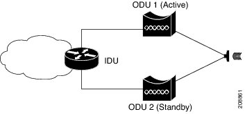
Figure 15-3 shows a sample physical topology for HSBY using two ODUs (active and standby) and one IDU.

Figure 15-3 HSBY Link Protection Physical Topology

In this topology, the IDU is connected to an active and a standby ODU. While only the active ODU handles data traffic, both ODUs process CFM and management traffic at all times. The HSBY implementation of CFM detects connectivity failures between the IDU and each ODU and indicates which ODU is active and handling traffic. In the event of a failure, the standby ODU assumes the role of the active ODU.

Suspending Continuity Check Messages

Under some circumstances such as a software upgrade or a device reload, it is necessary to temporarily suspend continuity check messages between the ODU and IDU in order to prevent unnecessary link protection action such as a failover. In this case, the ODU sets a suspend flag within the continuity check messages sent to the IDU indicating the amount of time until continuity check messages resume. The IDU resumes exchanging continuity check messages with the ODU after the suspend interval has passed or after the ODU recovers sends a continuity check message.


Note While the Cisco MWR 2941 processes continuity check suspend messages from the IDU, configuration of continuity check messages on the Cisco MWR 2941 is not supported.


HSBY Maintenance Associations

HSBY protocol uses two types of CFM continuity check messages:

E-CCM—An IDU-to-ODU continuity check message that functions at Ethernet CFM domain level 0. There are two active E-CCM sessions when HSBY is configured.

P-CCM—An ODU-to-ODU continuity check message that functions at Ethernet CFM domain level 4.


Note The IDU is only associated with the E-CCM sessions; it has outward-facing MEPs configured for each session.


Thus, the HSBY configuration shown in Figure 15-3 consists of five separate traffic flows:

CFM traffic between the IDU and ODU 1

CFM traffic between the IDU and the ODU 2

CFM traffic between ODU 1 and ODU 2. This traffic passes through IDU.

Data traffic between the WAN and ODU 1. This traffic passes through the IDU.

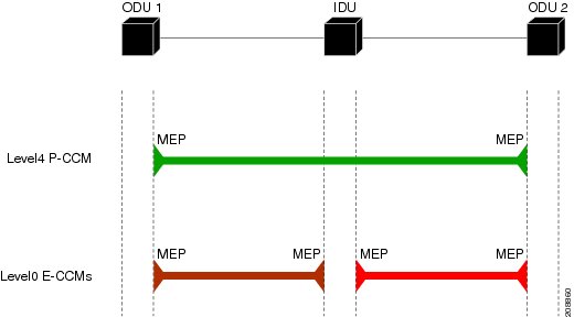
Figure 15-4 provides a logical view of the maintenance associations used in this HSBY topology.

Figure 15-4 HSBY Protocol CFM Maintenance Associations


Note To prevent switching loops on the management VLAN, we recommend that you enable RSTP on the management VLAN. For more information about how to configure RSTP, see "Understanding RSTP" section.


Configuring Microwave 1+1 Hot Standby Protocol

The following sections describe how to configure Microwave 1+1 Hot Standby Protocol (HSBY) on the Cisco MWR 2941.

ODU Configuration Values

IDU Configuration Values

Configuring HSBY

ODU Configuration Values

HSBY protocol specifies that some values on the ODU are configurable while others utilize fixed values. Table 15-6 summarizes the permitted values for an ODU using HSBY protocol.

Table 15-6 HSBY ODU Configuration Parameters Summary

Parameter
Default Value
Permitted Values

Short MA Name

Learned

0-65535

MPID

2

Fixed

MA VLAN-ID (E-CCM)

None

16-50


IDU Configuration Values

HSBY protocol specifies that some values on the IDU are configurable while others utilize fixed values. Table 15-7 summarizes the permitted values for an IDU using HSBY protocol.

Table 15-7 HSBY IDU Configuration Parameters Summary

Parameter
Default Value
Permitted Values

Domain Name

Null

Fixed

Domain Level

0

Fixed

Short MA Name

None

0-65535

MPID

1

Fixed

MA VLAN-ID (E-CCM)

None

1-15

CC Interval

100 ms

10 ms, 100 ms, and 1000 ms

Note Release 15.0(1)MR does not support 10ms CC intervals.

Suspend Interval

160 seconds

80 s, 160 s, 240 s, and 320 s


Configuring HSBY

Follow these steps to configure HSBY protocol on the Cisco MWR 2941.

 
Command
Purpose

Step 1 

configure terminal

Enters global configuration mode.

Step 2 

interface gigabitethernet slot/port

Enters configuration for the interface connected to ODU 1.

Note HSBY is permitted only on Gigabit Ethernet interfaces 0/0-0/5.

Step 3 

ethernet cfm mep domain domain-name mpid mpid {port | vlan vlan-id}

Defines a CFM MEP domain for ODU 1.

Step 4 

link-protection group group-number pccm vlan vlan-id

Specifies a link protection group for ODU 1.

Step 5 

interface gigabitethernet slot/port

Enters configuration for the interface connected to ODU 2

Step 6 

ethernet cfm mep domain domain-name mpid mpid {port | vlan vlan-id}

Defines a CFM MEP domain for ODU 2.

Step 7 

link-protection group group-number pccm vlan vlan-id

Specifies a link protection group for ODU 2.

Step 8 

ethernet cfm domain domain-name level level-id [direction outward]

Configures the CFM MEP domain for ODU 1.

Step 9 

id {mac-address domain-number | dns dns-name | null}

Example:

Router(config)# id null

Defines a the maintenance domain identifier (MDID) for ODU 1 as null.

Step 10 

service {ma-name | ma-num | vlan-id vlan-id | vpn-id vpn-id} [port | vlan vlan-id [direction down]]

Defines a maintenance association for ODU 1.

Step 11 

continuity-check

Enables transmission of continuity check messages (CCMs) within the ODU 1 maintenance association.

Step 12 

continuity-check [interval time | loss-threshold threshold | static rmep]

Defines a continuity-check interval for the ODU 1 maintenance association.

Step 13 

ethernet cfm domain domain-name level level-id [direction outward]

Configures the CFM MEP domain for ODU 2.

Step 14 

id {mac-address domain-number | dns dns-name | null}

Example:

Router(config)# id null

Defines a the MDID for ODU 2 as null.

Step 15 

service {ma-name | ma-num | vlan-id vlan-id | vpn-id vpn-id} [port | vlan vlan-id [direction down]]

Defines a maintenance association for ODU 2.

Step 16 

continuity-check

Enables transmission of CCMs within the ODU 2 maintenance association.

Step 17 

continuity-check [interval time | loss-threshold threshold | static rmep]

Defines a continuity-check interval for the ODU 2 maintenance association.

Step 18 

link-protection enable

Globally enables link protection on the router.

Step 19 

link-protection group management vlan vlan-id

Defines the management VLAN used for link protection.

Step 20 

ethernet cfm ieee

Enables the Ethernet Connectivity Fault Management 802.1ag Standard (CFM IEEE) version of CFM.

Step 21 

ethernet cfm global

Enables Ethernet connectivity fault management (CFM) globally.

Step 22 

end

Returns to privileged EXEC mode.

Step 23 

copy running-config startup-config

(Optional) Saves your entries in the configuration file.

Step 24 

show link-protection [detail [group group-number]]

(Optional) Displays the status of configured link protection groups.

Step 25 

show link-protection statistics [interface interface-name slot/port]

(Optional) Displays the counters for each link protection port.

Configuration Examples

Ethernet OAM and CFM Configuration: Example

CFM and ELMI Sample Configuration: Example

HSBY Sample Configuration: Example

Ethernet OAM and CFM Configuration: Example

These are example configurations of the interworking between Ethernet OAM and CFM in a sample service provider network with a provider-edge device connected to a customer edge device at each endpoint. You must configure CFM, E-LMI, and Ethernet OAM between the customer edge and the provider edge devices.

Customer-edge device 1 (CE1) configuration:

Router# config t
Router(config)# interface gigabitethernet1/0/1
Router(config-if)# switchport trunk allowed vlan 10
Router(config-if)# switchport mode trunk
Router(config-if)# ethernet oam remote-loopback supported
Router(config-if)# ethernet oam
Router(config-if)# exit

Provider-edge device 1 (PE1) configuration:

Router# config t
Router(config)# interface gigabitethernet1/0/20
Router(config-if)# switchport trunk encapsulation dot1q
Router(config-if)# switchport mode trunk
Router(config-if)# ethernet cfm mip 
Router(config-if)# ethernet cfm mep mpid 100 vlan 10
Router(config-if)# ethernet uni id 2004-20
Router(config-if)# ethernet oam remote-loopback supported
Router(config-if)# ethernet oam
Router(config-if)# service instance 10 ethernet BLUE
Router(config-if-srv)# ethernet lmi ce-vlan map 10
Router(config-if-srv)# exit

Provider-edge device 2 (PE2) configuration:

Router# config t
Router(config)# interface gigabitethernet1/1/20
Router(config-if)# switchport mode trunk
Router(config-if)# ethernet cfm mip 
Router(config-if)# ethernet cfm mep mpid 101 vlan 10
Router(config-if)# ethernet uni id 2004-20
Router(config-if)# ethernet oam remote-loopback supported
Router(config-if)# ethernet oam
Router(config-if)# service instance 10 ethernet BLUE
Router(config-if-srv)# ethernet lmi ce-vlan map 10
Router(config-if-srv)# exit

Customer-edge device 2 (CE2) configuration:

Router# config t
Router(config)# interface gigabitethernet1/0/1
Router(config-if)# switchport trunk allowed vlan 10
Router(config-if)# switchport mode trunk
Router(config-if)# ethernet oam remote-loopback supported
Router(config-if)# ethernet oam
Router(config-if)# exit

These are examples of the output showing provider-edge switch port status of the configuration. Port status shows as UP at both switches.

PE1:

Router# show ethernet cfm maintenance points remote
MPID  Level Mac Address    Vlan PortState InGressPort     Age(sec) Service ID
101 * 4     0015.633f.6900 10   UP        Gi1/1/1         27       blue

PE2:

Router# show ethernet cfm maintenance points remote
MPID  Level Mac Address    Vlan PortState InGressPort     Age(sec) Service ID
100 * 4     0012.00a3.3780 10   UP        Gi1/1/1         8        blue
Total Remote MEPs: 1

This example shows the outputs when you start remote loopback on CE1 (or PE1). The port state on the remote PE switch shows as Test and the remote CE switch goes into error-disable mode.

Router# ethernet oam remote-loopback start interface gigabitEthernet 0/1
This is a intrusive loopback.
Therefore, while you test Ethernet OAM MAC connectivity,
you will be unable to pass traffic across that link.
Proceed with Remote Loopback? [confirm]

PE1:

Router# show ethernet cfm maintenance points remote
MPID  Level Mac Address    Vlan PortState InGressPort     Age(sec) Service ID
101 * 4     0015.633f.6900 10   UP        Gi1/1/1         27       blue

PE2:

Router# show ethernet cfm maintenance points remote
MPID  Level Mac Address    Vlan PortState InGressPort     Age(sec) Service ID
100 * 4     0012.00a3.3780 10   TEST      Gi1/1/1         8        blue
Total Remote MEPs: 1

In addition, if you shut down the CE1 interface that connects to PE1, the remote PE2 port will show a PortState of Down.

CFM and ELMI Sample Configuration: Example

The following sample configuration uses CFM and ELMI with three inward facing MEPs, two MIPs, and three maintenance domains.


Note This section provides partial configurations intended to demonstrate a specific feature.


!
ethernet cfm ieee 
ethernet cfm global
ethernet cfm traceroute cache
ethernet cfm traceroute cache size 112
ethernet cfm domain CISCO_7 
 service L7 vlan 700
  continuity-check
!         
ethernet cfm domain CISCO_ENG
 service ce28 vlan 600
  continuity-check
!
ethernet cfm domain CISCO_5 
 service L5 vlan 1
  continuity-check
!
ethernet lmi global
!
interface GigabitEthernet0/2
 switchport access vlan 600
 shutdown
 ethernet cfm mip vlan 600
 ethernet cfm mep domain CISCO_ENG mpid 629 vlan 600
!         
interface GigabitEthernet0/3
 switchport mode trunk
 shutdown
 ethernet cfm mep domain CISCO_5 mpid 529 vlan 1
!         
interface GigabitEthernet0/4
 switchport access vlan 700
 shutdown 
 ethernet cfm mep domain CISCO_7 mpid 729 vlan 700
!        
interface GigabitEthernet0/5
 switchport mode trunk
 ethernet cfm mip vlan 1-2,100,600,700
! 

HSBY Sample Configuration: Example

!
link-protection enable
link-protection management vlan 51
link-protection group 2 pccm vlan 16
!
ethernet cfm ieee 
ethernet cfm global
!
ethernet cfm domain LPG1 level 0
 id null
 service number 100 vlan 10 direction down
  continuity-check
  continuity-check interval 100ms
!         
ethernet cfm domain LPG2 level 0
 id null
 service number 200 vlan 11 direction down
  continuity-check
  continuity-check interval 10ms
!         
interface GigabitEthernet0/3
 ethernet cfm mep domain LPG1 mpid 1 vlan 10
   link-protection group 12
!
interface GigabitEthernet0/4
 ethernet cfm mep domain LPG2 mpid 1 vlan 11
    link-protection group 12
!